28

GDA28
GDA 29
GDA
63-
2500
A
GDA30
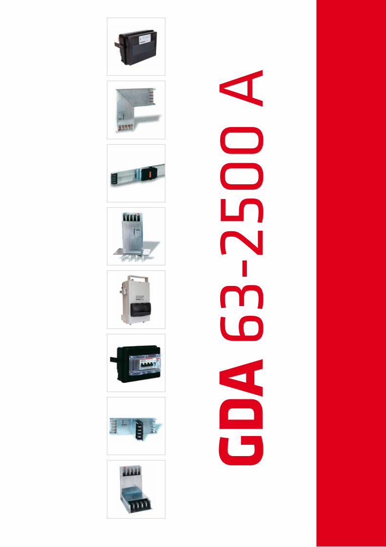
• Involucro esterno in alluminio• Giunto monobullone• Conduttori in alluminio e in rame con profilo appositamente progettato per sfruttare meglio l’effetto pelle• Grado di protezione da IP50 a IP55• Elementi rettilinei standard di 4 m• Sezione del Neutro sempre pari al 100% della fase• GDA 4: conduttore di PE involucro con sezione sempre superiore alla fase• GDA 5: conduttore di PE dedicato in alluminio• GDA 6: conduttore di PE dedicato e isolato• Derivazioni su entrambi i lati • Cassette di derivazione inseribili sotto tensione
• Aluminium housing • One bolt joint• Aluminium and copper conductors have been specially designed to make the most of SKIN EFFECT• Protection degree trom IP50 to IP55 • 4 metres standard straight elements• Neutral always like the 100% of phase section• GDA 4: PE housing with section always bigger than phase section• GDA 5: PE dedicated conductor in aluminium• GDA 6: PE dedicated and insulated conductor (“clean earth”)• Plug-in access opening on each side • Tap off boxes plug-in type in live conditions
Sistemidi distribuzionePlug-in busbar
63-2500 A
GDA è conforme alle norme:GDA complies with the following standard:
IEC 61439-1IEC 61439-6CEI EN 61439-1CEI EN 61439-6DIV VDE 0660 part 500DIN VDE 0660 part 502
GDA 31
AGDA 4 GDA 5
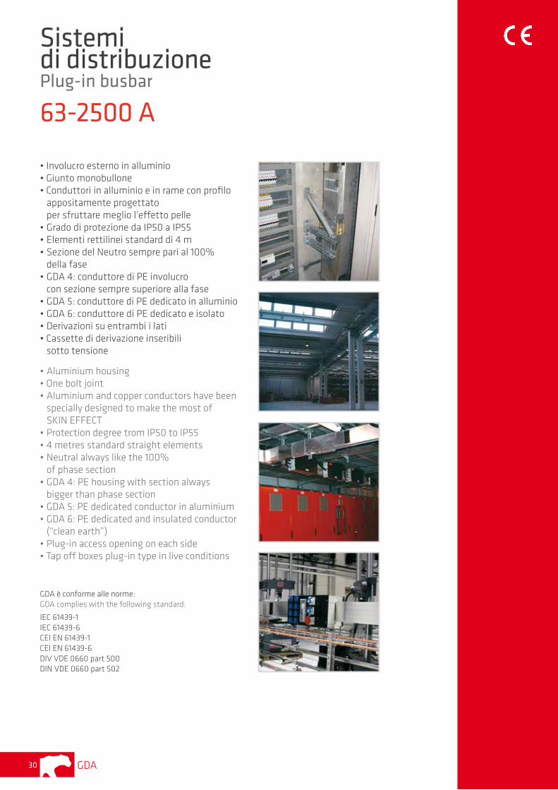
Codice/Code Kg/m Codice/Code Kg/m N° derivazioniTap off points
63 GDA100630 3,0 GDA200630 3,3 4+0
100 GDA1 00000 3,1 GDA200000 3,4 4+0
160 GDA101000M 3,3 GDA201000M 3,6 4+0
250 GDA102000 4,4 GDA202000 4,7 4+4
400 GDA104000 6,2 GDA204000 6,5 4+4
500 GDA105000 7,7 GDA205000 8,4 4+4
630 GDA106000 9,0 GDA206000 9,7 4+4
800 GDA108000 10,0 GDA208000 10,7 4+4
1000 GDA110000 11,3 GDA210000 12,1 4+4
1250 GDA112000 14,7 GDA212000 15,6 4+0
1600 GDA116000 17,7 GDA216000 18 4+0
2000 GDA120000 25 GDA220000 26 4+4
2500 GDA125000 28 GDA225000 29 4+4
ELEMENTI RETTILINEI • STRAIGHT ELEMENTS
AGDA 4 GDA 5
Codice/Code Codice/Code
63 GDA100631 GDA200631
100 GDA100001 GDA200001
160 GDA101001M GDA201001M
250 GDA102001 GDA202001
400 GDA104001 GDA204001
500 GDA105001 GDA205001
630 GDA106001 GDA206001
800 GDA108001 GDA208001
1000 GDA110001 GDA210001
1250 GDA112001 GDA212001
1600 GDA116001 GDA216001
2000 GDA120001 GDA220001
2500 GDA125001 GDA225001
Il numero delle predisposizioni per le derivazioni varia a seconda della lunghezza dell’elemento. The number of plug-in points depends on the length of elements.
AGDA 4 GDA 5
Codice/Code Codice/Code
63 GDA100632 GDA200632
100 GDA100002 GDA200002
160 GDA101002M GDA201002M
250 GDA102002 GDA202002
400 GDA104002 GDA204002
500 GDA105002 GDA205002
630 GDA106002 GDA206002
800 GDA108002 GDA208002
1000 GDA110002 GDA210002
1250 GDA112002 GDA212002
1600 GDA116002 GDA216002
2000 GDA120002 GDA220002
2500 GDA125002 GDA225002
Il numero delle predisposizioni per le derivazioni varia a seconda della lunghezza dell’elemento. The number of plug-in points depends on the length of elements.
0,3 - 1,90 m
1,91 - 3,99 m
250
196
1
2
Giunzione • Joint
AGDA 4 GDA 5L (mm) L (mm)
63 - 100 - 160 45 45
250 - 400 65 65
500 - 630 - 800 - 1000 94 94
1250 - 1600 145 145
2000 - 2500 270 270
L
191
N
L1
L2
L3
N
L1
L2
L3
191
L
PE
Il giunto è sempre incluso in ogni elemento. Gli elementi rettilinei sono IP50, elevabili a IP55 con gli appositi accessori.
The joint is always included in each element.Straight elements are IP50, it is possible to have IP55 with accessories.
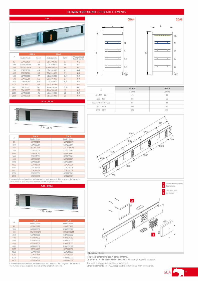
4 m
0,3 - 1,90 m
1,91 - 3,99 m
4000
1000
1000
1000
285
715
1000
1000
1000
225
775
N
GDA4 GDA5
1 Giunto monobullone2 Coprigiunto
1 One-bolt joint2 Joint cover
GDA32
ELEMENTI RETTILINEI • STRAIGHT ELEMENTS
AGDA 4 GDA 5CodiceCode
CodiceCode
N° derivazioniTap off points
63 GDA100630S GDA200630S 8+0
100 GDA100000S GDA200000S 8+0
160 GDA101000MS GDA201000MS 8+0
250 GDA102000S GDA202000S 8+0
400 GDA104000S GDA204000S 8+0
500 GDA105000S GDA205000S 8+0
630 GDA106000S GDA206000S 8+0
800 GDA108000S GDA208000S 8+0
1000 GDA110000S GDA210000S 8+0
1250 GDA112000S GDA212000S 8+0
1600 GDA116000S GDA216000S 8+0
2000 GDA120000S GDA220000S 8+0
2500 GDA125000S GDA225000S 8+0
A richiesta derivazioni ogni 0,25 m.On request plug-in points every 0,25 m.
AGDA 4 GDA 5
Codice/Code Codice/Code
63 GDA100632M2 GDA200632M2
100 GDA100002M2 GDA200002M2
160 GDA101002M2 GDA201002M2
250 GDA102002M2 GDA202002M2
400 GDA104002M2 GDA204002M2
500 GDA105002M2 GDA205002M2
630 GDA106002M2 GDA206002M2
800 GDA108002M2 GDA208002M2
1000 GDA110002M2 GDA210002M2
1250 GDA112002M2 GDA212002M2
1600 GDA116002M2 GDA216002M2
2000 GDA120002M2 GDA220002M2
2500 GDA125002M2 GDA225002M2
Ordine minimo: multipli di 2 pezzi.Minimum order: multiples of 2 pcs.
2 m
2 m
AGDA 4 GDA 5CodiceCode
CodiceCode
N° derivazioniTap off points
63 GDA100632M2S GDA200632M2S 4+0
100 GDA100002M2S GDA200002M2S 4+0
160 GDA101002M2S GDA201002M2S 4+0
250 GDA102002M2S GDA202002M2S 4+0
400 GDA104002M2S GDA204002M2S 4+0
500 GDA105002M2S GDA205002M2S 4+0
630 GDA106002M2S GDA206002M2S 4+0
800 GDA108002M2S GDA208002M2S 4+0
1000 GDA110002M2S GDA210002M2S 4+0
1250 GDA112002M2S GDA212002M2S 4+0
1600 GDA116002M2S GDA216002M2S 4+0
2000 GDA120002M2S GDA220002M2S 4+0
2500 GDA125002M2S GDA250002M2S 4+0
Ordine minimo: multipli di 2 pezzi.Minimum order: multiples of 2 pcs.
4 m CON DERIVAZIONI OGNI 0,5 m SOLO IN FRONTE 4 m WITH PLUG-IN POINTS EVERY 0,5 M ONLY IN FRONT
2 m
2 m CON DERIVAZIONI OGNI 0,5 m SOLO IN FRONTE 2 m WITH PLUG-IN POINTS EVERY 0,5 M ONLY IN FRONT
AGDA 4 GDA 5L (mm) L (mm)
63 - 100 - 160 45 45
250 - 400 65 65
500 - 630 - 800 - 1000 94 94
1250 - 1600 145 145
2000 - 2500 270 270
L
191
N
L1
L2
L3
N
L1
L2
L3
191
L
PE
GDA4 GDA5
250
196
1
2
Giunzione • Joint
Il giunto è sempre incluso in ogni elemento. Gli elementi rettilinei sono IP50, elevabili a IP55 con gli appositi accessori.
The joint is always included in each element.Straight elements are IP50, it is possible to have IP55 with accessories.
1 Giunto monobullone2 Coprigiunto
1 One-bolt joint2 Joint cover
4000
225
N
500
500
500
500
500
500
500
225
4000
275
500
500
500
500
500
500
500225
N
GDA 33
A
GDA 4 GDA 5DX SX DX SX
CodiceCode
CodiceCode
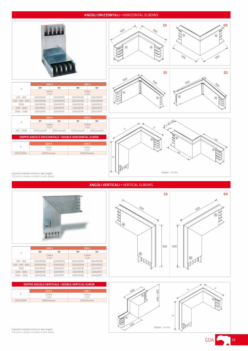
250 - 400 GDA100102 GDA100101 GDA200102 GDA200101
500 - 630 - 800 GDA100106 GDA100105 GDA200106 GDA200105
1000 GDA100116 GDA100115 GDA200116 GDA200115
1250 - 1600 GDA116116 GDA116115 GDA216116 GDA216115
2000 - 2500 GDA120116 GDA120115 GDA220116 GDA220115
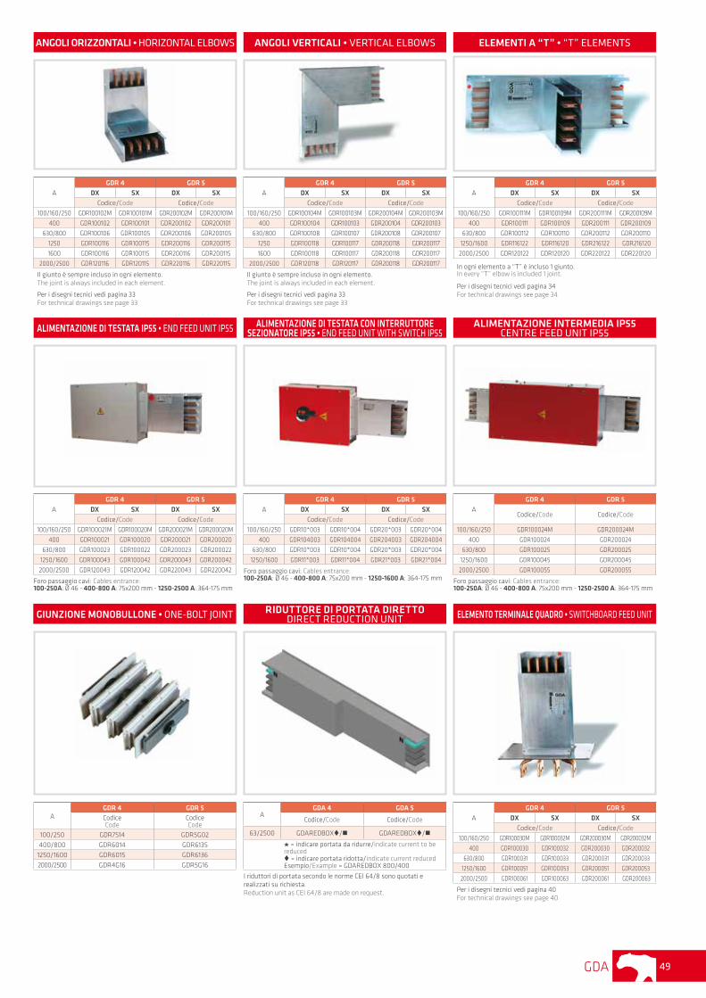
ANGOLI ORIZZONTALI • HORIZONTAL ELBOWS
500500
N N
SX
ANGOLI VERTICALI • VERTICAL ELBOWS
A
GDA 4 GDA 5DX SX DX SX
CodiceCode
CodiceCode
250 - 400 GDA100104 GDA100103 GDA200104 GDA200103
500 - 630 - 800 GDA100108 GDA100107 GDA200108 GDA200107
1000 GDA100118 GDA100117 GDA200118 GDA200117
1250 - 1600 GDA116118 GDA116117 GDA216118 GDA216117
2000 - 2500 GDA120118 GDA120117 GDA220118 GDA220117
500
500
N
N
500
500
min
= 4
32
DX
SX
500
500
N
N
DX
AGDA 4 GDA 5CodiceCode
CodiceCode
250/2500A GDA1Zxxxxxx GDA2Zxxxxxx
DOPPIO ANGOLO VERTICALE • DOUBLE VERTICAL ELBOW
AGDA 4 GDA 5CodiceCode
CodiceCode
250/2500A GDA1Zxxxxxx GDA2Zxxxxxx
DOPPIO ANGOLO ORIZZONTALE • DOUBLE HORIZONTAL ELBOW
500 500
N N
Il giunto è sempre incluso in ogni angolo. The joint is always included in each elbow.
YZ
X
N
N
Il giunto è sempre incluso in ogni angolo. The joint is always included in each elbow.
YZ
X
N
N
X = 2L+50
L
N
N
500
500
Doppio - Double
N
N
D1 D2
A
GDA 4 GDA 5D1 D2 D1 D2
CodiceCode
CodiceCode
250 - 2500 GDA1xxxxxD1 GDA1xxxxxD2 GDA2xxxxxD1 GDA2xxxxxD2
500500
N
N
500 500
NN
Doppio - Double
GDA34
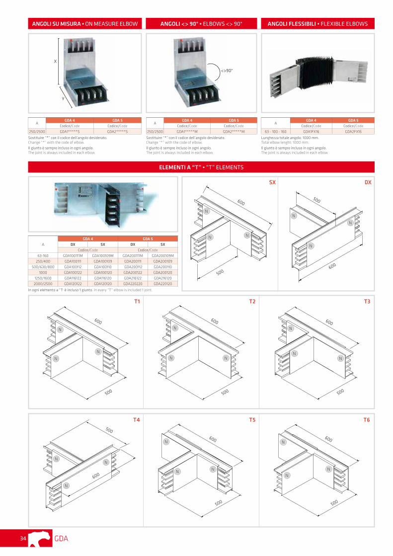
ANGOLI SU MISURA • ON MEASURE ELBOW ANGOLI <> 90° • ELBOWS <> 90° ANGOLI FLESSIBILI • FLEXIBLE ELBOWS
AGDA 4 GDA 5
Codice/Code Codice/Code
250/2500 GDA1*****S GDA2*****S
Sostituire “*” con il codice dell’angolo desiderato. Change “*” with the code of elbow.Il giunto è sempre incluso in ogni angolo. The joint is always included in each elbow.
X
y
<>90°
AGDA 4 GDA 5
Codice/Code Codice/Code
250/2500 GDA1*****M GDA2*****M
Sostituire “*” con il codice dell’angolo desiderato. Change “*” with the code of elbow.Il giunto è sempre incluso in ogni angolo. The joint is always included in each elbow.
AGDA 4 GDA 5
Codice/Code Codice/Code
63 - 100 - 160 GDA1FX16 GDA2FX16
Lunghezza totale angolo: 1000 mm. Total elbow lenght: 1000 mm.Il giunto è sempre incluso in ogni angolo.The joint is always included in each elbow.
A
GDA 4 GDA 5DX SX DX SX
Codice/Code Codice/Code
63-160 GDA100111M GDA100109M GDA200111M GDA200109M
250/400 GDA100111 GDA100109 GDA200111 GDA200109
500/630/800 GDA100112 GDA100110 GDA200112 GDA200110
1000 GDA100122 GDA100120 GDA200122 GDA200120
1250/1600 GDA116122 GDA116120 GDA216122 GDA216120
2000/2500 GDA120122 GDA120120 GDA220220 GDA220120
In ogni elemento a “T· è incluso 1 giunto. In every “T” elbow is included 1 joint.
ELEMENTI A “T” • “T” ELEMENTS
600
500
N
N N
600
500
N
N
N
SX DX
N
N
600
500
T1
NN
N
600
500
T4
N
600
500
T2
N N
600
500
T5
N
N
600
500
T3
T6
N
600
500
N NN N
NN
N
GDA 35
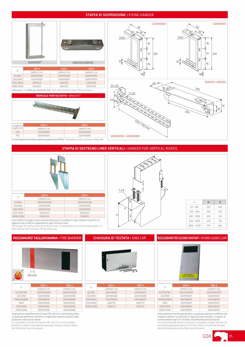
PASSAMURO TAGLIAFIAMMA • FIRE BARRIER CHIUSURA DI TESTATA • END CAP BLOCCASBARRE PER COLONNE MONTANTI • INTERNAL BUSBAR CLAMP
AGDA 4 GDA 5
Codice/Code Codice/Code
63/100/160 GDA104007M GDA204007M
250/400 GDA104007 GDA204007
500/630/800 GDA108007 GDA208007
1000 GDA110007 GDA210007
1250/1600 GDA160007 GDA260007
2000/2500 GDA120007 GDA220007
Il bloccasbarre è fornito premontato su qualsiasi elemento rettilineo (da ordinare a parte) e va utilizzato in ogni percorso verticale, in ragione di un bloccasbarre ogni 12 m di linea, iniziando dal punto più basso. The internaI busbar clamp is inserted in a standard straight element (to be ordered separately) every 12 m of line. Start to mount the element with internaI busbar clamp from lower line point.
AGDA 4 GDA 5
Codice/Code Codice/Code
63/160 GDA100027 GDA100027
250/400 GDA100028 GDA100028
500/1000 GDA100029 GDA100029
1250/1600 GDACT4 GDACT4
2000/2500 GDACT5 GDACT5
AGDA 4 GDA 5
Codice/Code Codice/Code
63/100/160 GDA101006M GDA201006M
250/400 GDA104006 GDA204006
500/630/800 GDA108006 GDA208006
1000 GDA110006 GDA210006
1250/1600 GDA116006 GDA216006
2000/2500 GDA125006 GDA225006
Il passamuro tagliafiamma di classe REI 120 (2 h) viene premontato su qualsiasi elemento rettilineo o angolo (da ordinare a parte) nella posizione indicata dal cliente. It is possibile to set the fire barrier, REI 120 (2 h), in any straight element or elbow to be ordered separately. Always indicate where the fire barrier has to be piaced.
STAFFA DI SOSTEGNO LINEE VERTICALI • HANGER FOR VERTICAL RISERS
AGDA 4 GDA 5
Codice/Code Codice/Code
63/160 GDA010002M GDA010002M
250/400 GDA010002 GDA010002
500/1000 GDA010003 GDA010003
1250/1600 GDASSV4 GDASSV4
2000/2500 GDASSV5 GDASSV
Una staffa di sostegno linee verticali deve essere installata in ogni colonna montante, in aggiunta alla staffe di sospensione e ogni 150 kg di linea. One hanger for vertical risers must be foresees, in additional of universal fixing hangers, in each vertical riser and every 150 kg of busway.
7 x 8
H
X
A H X
63 - 160 200 100
250 - 400 200 100
500 - 1000 200 125
1250 - 1600 234 153
2000 - 2500 234 285
AGDA 4 GDA 5 INOX
Codice/Code Codice/Code Codice/Code
63/160 GDA010000 GDA010000 GDA01000X
250/1000 GDA010001 GDA010001 GDA01000X
1250/1600 GDASS4 GDASS4 GDASS4X
2000/2500 GDASS5 GDASS5 GDASS5X
Utilizzare n. 2 staffe per elemento GDA. Each GDA element need 2 fixing hangers.
GDA01000* GDASS4/GDASS5
STAFFA DI SOSPENSIONE • FIXING HANGER
GDASS4 • GDASS5
GDA010001
Lunghezza Lenght (mm)
GDA 4 GDA 5Codice/Code Codice/Code
550 GDA010004 GDA010004
750 GDA010005 GDA010005
Le mensole possono essere usate sia a parete sia a soffitto. The brackets can be used wall or ceiling side.
79
39
7x20
15
30
76
72
76
224
123
59
7x20
15
30
76
72
76
224
550 / 750 mm
12 x 20
7 x 2560
60170
330
60
70
26530
1335
MENSOLE PORTASTAFFE • BRACKET
GDA010000
GDA010004 • GDA010005
150 mm
GDA36
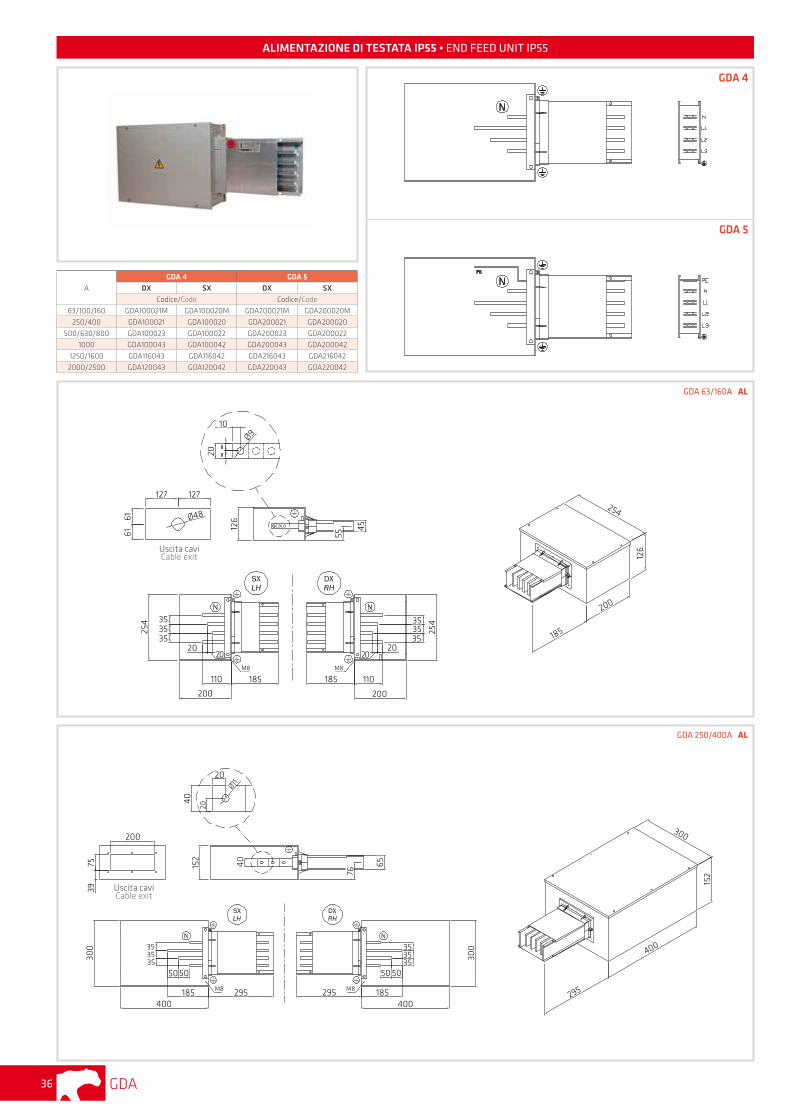
ALIMENTAZIONE DI TESTATA IP55 • END FEED UNIT IP55
A
GDA 4 GDA 5DX SX DX SX
Codice/Code Codice/Code
63/100/160 GDA100021M GDA100020M GDA200021M GDA200020M
250/400 GDA100021 GDA100020 GDA200021 GDA200020
500/630/800 GDA100023 GDA100022 GDA200023 GDA200022
1000 GDA100043 GDA100042 GDA200043 GDA200042
1250/1600 GDA116043 GDA116042 GDA216043 GDA216042
2000/2500 GDA120043 GDA120042 GDA220043 GDA220042
GDA 63/160A AL
GDA 250/400A AL
GDA 4
GDA 512
6
45
254 35
3535
2020
110
200
185M8
152
40 65
300 35
3535
5050
185400
295M8 M8295 185400
50 50
353535 30
0
295
400
152
300
Uscita caviCable exit
Uscita caviCable exit
185
200
126
254
25435
3535
185 110
200
2020
M8
55
10
20
Ø9
127 127
6161
Ø48
20
40
Ø11
20
200
7539
76
GDA 37
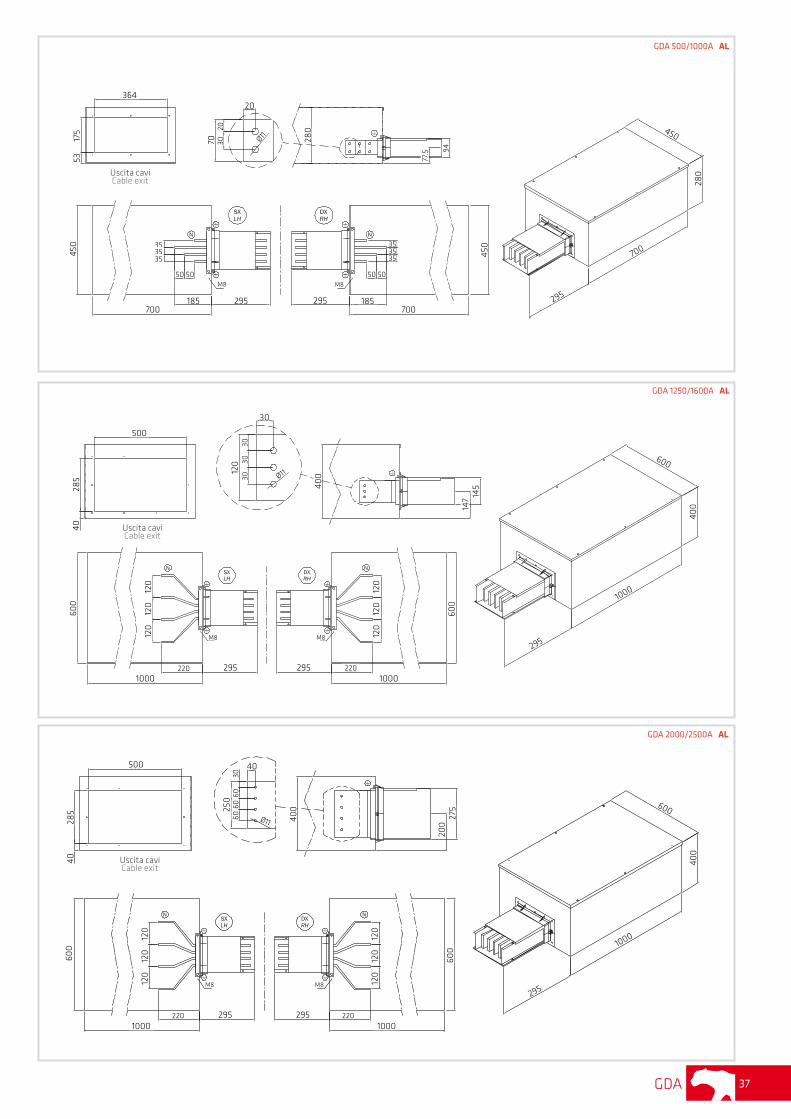
GDA 1250/1600A AL
GDA 500/1000A AL
GDA 2000/2500A AL
364
5317
5
70 3020
20
Ø11 280
77.5 94
450 35
3535
50 50
700185 295
M8 M8
45035
3535
50 50
295 185700
295
700
280
450
500
4028
5
120
30
30
Ø11
3030
400
147 14
5
295
1000
400
60060
0
120
120
120
295 2201000
M8M8
2952201000
120
120
120
600
500
4028
5 250
60
40
Ø11
30
400
200
27560
60
M8
2952201000
120
120
120
600
M8
295 2201000
120
120
120
600
295
1000
400
600
Uscita caviCable exit
Uscita caviCable exit
Uscita caviCable exit
GDA38
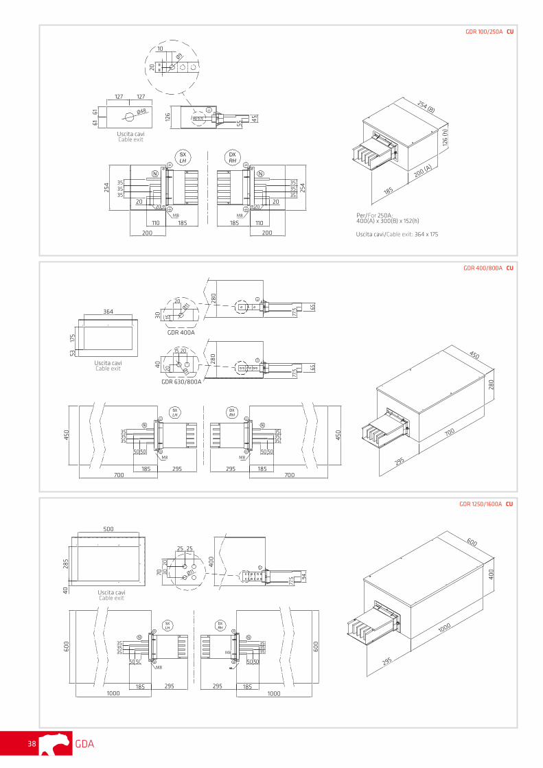
GDR 400/800A CU
GDR 100/250A CU
GDR 1250/1600A CU
364
5317
5
20
1530
GDR 400A
Ø11
2015
40
20 Ø11
280
280
6565
77.5
77.5
450 35
35
700185 295
35
M8
185295
M850 50
35
3535
50 50
450
700
295
700
280
450
500
285
40
25 25
7020
Ø1130
400
94
77.5
600 35
3535
50 50
295 1851000
2951000
35
50 50
3535
M8
M8 600
295
1000
185
400
600
Per/For 250A:400(A) x 300(B) x 152(h)
Uscita cavi/Cable exit: 364 x 175
Uscita caviCable exit
Uscita caviCable exit
127
Uscita caviCable exit
61
20
10
Ø9
126
61127
Ø48
45
M8
254 35
3535
2020
110 185
200 200
M8
110185
353535
254
185
200 (A)
126
(h)
254 (B)
55
2020
GDR 630/800A
GDA 39
[A] A B C D
63 650 355 260 130100/160 650 355 260 130
250/400 800 500 450 250
500/1000 1050 750 500 320
1250/1600 1300 1000 600 450
A
B
D
C
N
A
B
D
C
N
SX DX
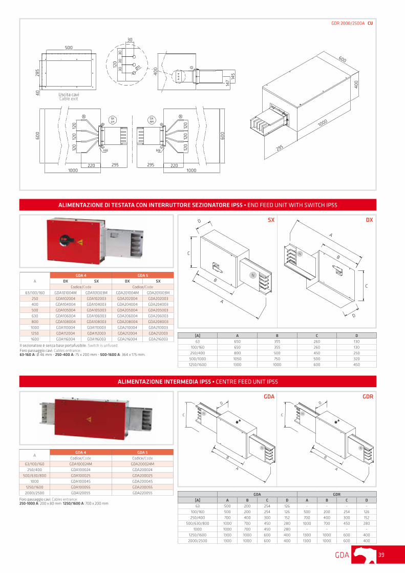
GDR 2000/2500A CU
ALIMENTAZIONE DI TESTATA CON INTERRUTTORE SEZIONATORE IP55 • END FEED UNIT WITH SWITCH IP55
A
GDA 4 GDA 5DX SX DX SX
Codice/Code Codice/Code
63/100/160 GDA101004M GDA101003M GDA201004M GDA201003M
250 GDA102004 GDA102003 GDA202004 GDA202003
400 GDA104004 GDA104003 GDA204004 GDA204003
500 GDA105004 GDA105003 GDA205004 GDA205003
630 GDA106004 GDA106003 GDA206004 GDA206003
800 GDA108004 GDA108003 GDA208004 GDA208003
1000 GDA110004 GDA110003 GDA210004 GDA210003
1250 GDA112004 GDA112003 GDA212004 GDA212003
1600 GDA116004 GDA116003 GDA216004 GDA216003
Il sezionatore è senza base portafusibile. Switch is unfused.Foro passaggio cavi: Cables entrance: 63-160 A: Ø 46 mm - 250-400 A: 75 x 200 mm - 500-1600 A: 364 x 175 mm.
AGDA 4 GDA 5
Codice/Code Codice/Code
63/100/160 GDA100024M GDA200024M
250/400 GDA100024 GDA200024
500/630/800 GDA100025 GDA200025
1000 GDA100045 GDA200045
1250/1600 GDA100055 GDA200055
2000/2500 GDA120055 GDA220055
Foro passaggio cavi: Cables entrance: 250-1000 A: 200 x 80 mm 1250/1600 A: 700 x 200 mm
ALIMENTAZIONE INTERMEDIA IP55 • CENTRE FEED UNIT IP55
C
D
B
A
N
N
C
D
B
A
N
N
GDA GDR
[A] A B C D A B C D
63 500 200 254 126 - - - -100/160 500 200 254 126 500 200 254 126
250/400 700 400 300 152 700 400 300 152
500/630/800 1000 700 450 280 1000 700 450 280
1000 1000 700 450 280 - - - -
1250/1600 1300 1000 600 400 1300 1000 600 400
2000/2500 1300 1000 600 400 1300 1000 600 400
GDA GDR
500
285
40
120
3030
30
30
Ø11
400
147 14
5
600
120
120
120
1000220 295
M8 M8
295 2201000
120
120
120
600
600
400
1000
295
Uscita caviCable exit
GDA40
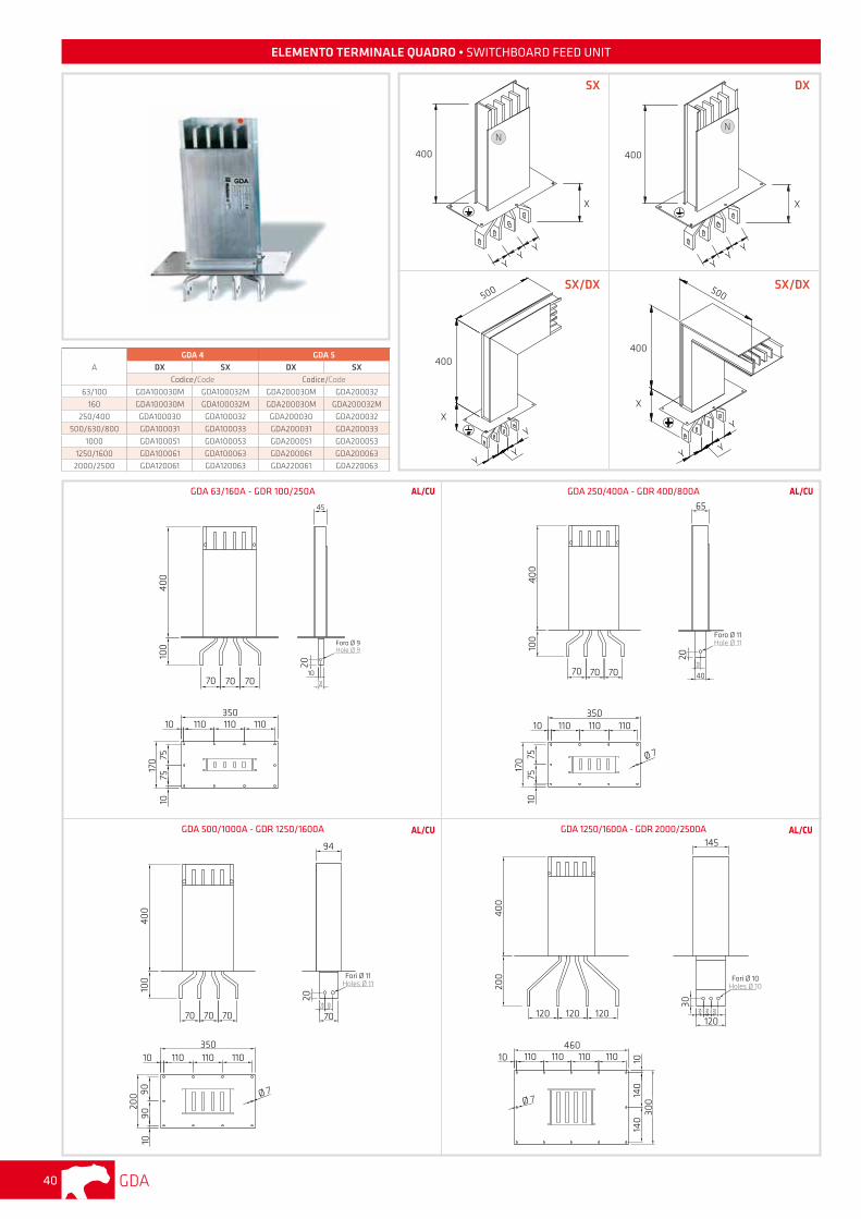
ELEMENTO TERMINALE QUADRO • SWITCHBOARD FEED UNIT
A
GDA 4 GDA 5DX SX DX SX
Codice/Code Codice/Code
63/100 GDA100030M GDA100032M GDA200030M GDA200032
160 GDA100030M GDA100032M GDA200030M GDA200032M
250/400 GDA100030 GDA100032 GDA200030 GDA200032
500/630/800 GDA100031 GDA100033 GDA200031 GDA200033
1000 GDA100051 GDA100053 GDA200051 GDA200053
1250/1600 GDA100061 GDA100063 GDA200061 GDA200063
2000/2500 GDA120061 GDA120063 GDA220061 GDA220063
400
X
YY
Y
N
400
X
N
Hole Ø11
400
100
70 70 7020
4020
Foro Ø 11Hole Ø 11
65
350110 110 11010
170 75
7510
Ø 7
Holes Ø11
20
7020
Fori Ø 11Holes Ø 11
94
30
400
100
350110 110 11010
200 90
9010
Ø 7
70 70 70
Holes Ø10
400
200
120 120 120
30
12030
Fori Ø 10Holes Ø 10
145
30 30
GDA 63/160A - GDR 100/250A AL/CU
Hole Ø9
400
100
70 70 70
20
10
20
Foro Ø 9Hole Ø 9
45
350110 110 11010
170 75
7510
GDA 250/400A - GDR 400/800A AL/CU
GDA 500/1000A - GDR 1250/1600A AL/CU GDA 1250/1600A - GDR 2000/2500A AL/CU
SX DX
460110 110 110 11010
Ø 7
300
140
140
10
YY
Y
400
X
500
Y
YY
400
X
Y
YY
500SX/DX SX/DX
GDA 41
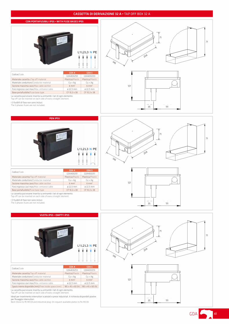
Codice/CodeGDA 4 GDA 5
GDA400250 GDA400250
Materiale cassetta /Tap off material Plastica/Plastic Plastica/Plastic
Materiale conduttore/Conductor material Cu + Ag Cu + Ag
Sezione massima cavo/Max cable sectlon 6 mm2 6 mm2
Foro ingresso cavi max/Max. entrance cable ø 22,5 mm ø 22,5 mm
Base portafusibile/Fuse base type CF 10,3 x 38 CF 10,3 x 38
La cassetta può essere inserita su entrambi i lati di ogni elemento. Tap off can be inserted on each side of every straight element.
I 3 fusibili di fase non sono inclusi.The 3 phases fuses are not included.
Codice/CodeGDA 4 GDA 5
GDA400251 GDA400251
Materiale cassetta/Tap off material Plastica/Plastic Plastica/Plastic
Materiale conduttore/Conductor material Cu + Ag Cu + Ag
Sezione massima cavo/Max cable sectlon 6 mm2 6 mm2
Foro ingresso cavi max/Max. entrance cable ø 22,5 mm ø 22,5 mm
Base portafusibile/Fuse base type CF 10,3 x 38 CF 10,3 x 38
La cassetta può essere inserita su entrambi i lati di ogni elemento. Tap off can be inserted on each side of every straight element.
I 3 fusibili di fase non sono inclusi.The 3 phases fuses are not included.
CASSETTA DI DERIVAZIONE 32 A • TAP OFF BOX 32 A
Codice/CodeGDA 4 GDA 5
GDA400253 GDA400253
Materiale cassetta/Tap off material Plastica/Plastic Plastica/Plastic
Materiale conduttore/Conductor material Cu + Ag Cu + Ag
Sezione massima cavo/Max cable sectlon 6 mm2 6 mm2
Foro ingresso cavi max/Max. entrance cable ø 22,5 mm ø 22,5 mm
Spazio interno disponibile (mm)/Free inside space (mm) 185 x 45 x 60 (h) 185 x 45 x 60 (h)
La cassetta può essere inserita su entrambi i lati di ogni elemento. Tap off can be inserted on each side of every straight element.
Ideali per inserimento interruttori scatolati e prese industriali. A richiesta disponibili piastre per fissaggio interruttori.Best choice to fit MCCB and industrial plug. On request available plates to fix MCCB.
CON PORTAFUSIBILI IP55 • WITH FUSE BASES IP55
PEN IP55
VUOTA IP55 • EMPTY IP55
146
204
71
71
121
11135
146
204
71
71
121
11135
146
204
71
71
121
11135
GDA42
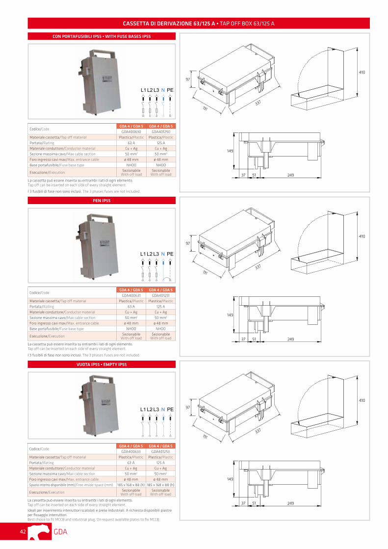
CASSETTA DI DERIVAZIONE 63/125 A • TAP OFF BOX 63/125 A
Codice/CodeGDA 4 / GDA 5 GDA 4 / GDA 5
GDA400630 GDA401250
Materiale cassetta/Tap off material Plastica/Plastic Plastica/Plastic
Portata/Rating 63 A 125 A
Materiale conduttore/Conductor material Cu + Ag Cu + Ag
Sezione massima cavo/Max cable sectlon 50 mm2 50 mm2
Foro ingresso cavi max/Max. entrance cable ø 48 mm ø 48 mm
Base portafusibile/Fuse base type NHOO NHOO
Esecuzione/Execution SezionabileWith off load
SezionabileWith off load
La cassetta può essere inserita su entrambi i lati di ogni elemento. Tap off can be inserted on each side of every straight element.
I 3 fusibili di fase non sono inclusi. The 3 phases fuses are not included.
Codice/CodeGDA 4 / GDA 5 GDA 4 / GDA 5
GDA400631 GDA401251
Materiale cassetta/Tap off material Plastica/Plastic Plastica/Plastic
Portata/Rating 63 A 125 A
Materiale conduttore/Conductor material Cu + Ag Cu + Ag
Sezione massima cavo/Max cable sectlon 50 mm2 50 mm2
Foro ingresso cavi max/Max. entrance cable ø 48 mm ø 48 mm
Base portafusibile/Fuse base type NHOO NHOO
Esecuzione/Execution SezionabileWith off load
SezionabileWith off load
La cassetta può essere inserita su entrambi i lati di ogni elemento. Tap off can be inserted on each side of every straight element.
I 3 fusibili di fase non sono inclusi. The 3 phases fuses are not included.
Codice/CodeGDA 4 / GDA 5 GDA 4 / GDA 5
GDA400633 GDA401253
Materiale cassetta/Tap off material Plastica/Plastic Plastica/Plastic
Portata/Rating 63 A 125 A
Materiale conduttore/Conductor material Cu + Ag Cu + Ag
Sezione massima cavo/Max cable sectlon 50 mm2 50 mm2
Foro ingresso cavi max/Max. entrance cable ø 48 mm ø 48 mm
Spazio interno disponibile (mm)/Free inside space (mm) 185 x 168 x 88 (h) 185 x 168 x 88 (h)
Esecuzione/Execution SezionabileWith off load
SezionabileWith off load
La cassetta può essere inserita su entrambi i lati di ogni elemento. Tap off can be inserted on each side of every straight element.Ideali per inserimento interruttori scatolati e prese industriali. A richiesta disponibili piastre per fissaggio interruttori. Best choice to fit MCCB and industrial plug. On request available plates to fix MCCB.
CON PORTAFUSIBILI IP55 • WITH FUSE BASES IP55
PEN IP55
VUOTA IP55 • EMPTY IP55
191337
97
410
149
2495137
191337
97
410
149
2495137
191337
97
410
149
2495137
GDA 43
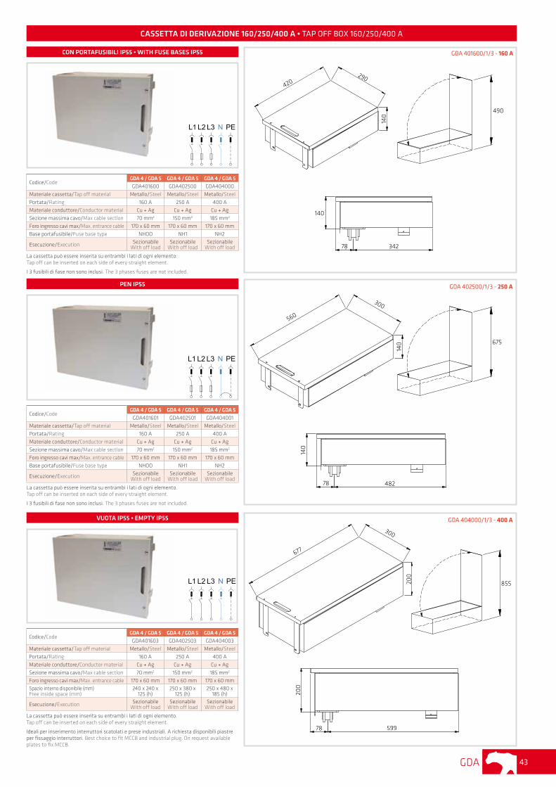
CASSETTA DI DERIVAZIONE 160/250/400 A • TAP OFF BOX 160/250/400 A
Codice/CodeGDA 4 / GDA 5 GDA 4 / GDA 5 GDA 4 / GDA 5GDA401600 GDA402500 GDA404000
Materiale cassetta/Tap off material Metallo/Steel Metallo/Steel Metallo/Steel
Portata/Rating 160 A 250 A 400 A
Materiale conduttore/Conductor material Cu + Ag Cu + Ag Cu + Ag
Sezione massima cavo/Max cable sectlon 70 mm2 150 mm2 185 mm2
Foro ingresso cavi max/Max. entrance cable 170 x 60 mm 170 x 60 mm 170 x 60 mm
Base portafusibile/Fuse base type NHOO NH1 NH2
Esecuzione/Execution SezionabileWith off load
SezionabileWith off load
SezionabileWith off load
La cassetta può essere inserita su entrambi i lati di ogni elemento. Tap off can be inserted on each side of every straight element.
I 3 fusibili di fase non sono inclusi. The 3 phases fuses are not included.
Codice/CodeGDA 4 / GDA 5 GDA 4 / GDA 5 GDA 4 / GDA 5
GDA401601 GDA402501 GDA404001
Materiale cassetta/Tap off material Metallo/Steel Metallo/Steel Metallo/Steel
Portata/Rating 160 A 250 A 400 A
Materiale conduttore/Conductor material Cu + Ag Cu + Ag Cu + Ag
Sezione massima cavo/Max cable sectlon 70 mm2 150 mm2 185 mm2
Foro ingresso cavi max/Max. entrance cable 170 x 60 mm 170 x 60 mm 170 x 60 mm
Base portafusibile/Fuse base type NHOO NH1 NH2
Esecuzione/Execution SezionabileWith off load
SezionabileWith off load
SezionabileWith off load
La cassetta può essere inserita su entrambi i lati di ogni elemento.Tap off can be inserted on each side of every straight element.
I 3 fusibili di fase non sono inclusi. The 3 phases fuses are not included.
Codice/CodeGDA 4 / GDA 5 GDA 4 / GDA 5 GDA 4 / GDA 5
GDA401603 GDA402503 GDA404003
Materiale cassetta/Tap off material Metallo/Steel Metallo/Steel Metallo/Steel
Portata/Rating 160 A 250 A 400 A
Materiale conduttore/Conductor material Cu + Ag Cu + Ag Cu + Ag
Sezione massima cavo/Max cable sectlon 70 mm2 150 mm2 185 mm2
Foro ingresso cavi max/Max. entrance cable 170 x 60 mm 170 x 60 mm 170 x 60 mmSpazio interno disponibile (mm) Free inside space (mm)
240 x 240 x 125 (h)
250 x 380 x 125 (h)
250 x 480 x 185 (h)
Esecuzione/Execution SezionabileWith off load
SezionabileWith off load
SezionabileWith off load
La cassetta può essere inserita su entrambi i lati di ogni elemento. Tap off can be inserted on each side of every straight element.
Ideali per inserimento interruttori scatolati e prese industriali. A richiesta disponibili piastre per fissaggio interruttori. Best choice to fit MCCB and industrial plug. On request available plates to fix MCCB.
560
300
140
677
300
200
490
675
855
140
48278
200
59978
GDA 401600/1/3 - 160 A
GDA 402500/1/3 - 250 A
GDA 404000/1/3 - 400 A
CON PORTAFUSIBILI IP55 • WITH FUSE BASES IP55
PEN IP55
VUOTA IP55 • EMPTY IP55
420290
140
140
78 342
GDA44
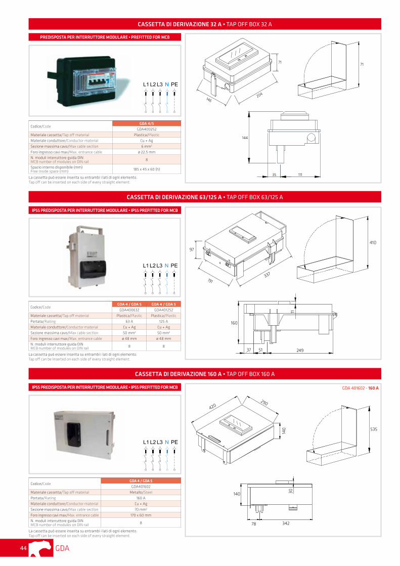
CASSETTA DI DERIVAZIONE 32 A • TAP OFF BOX 32 A
Codice/CodeGDA 4/5
GDA400252
Materiale cassetta/Tap off material Plastica/Plastic
Materiale conduttore/Conductor material Cu + Ag
Sezione massima cavo/Max cable sectlon 6 mm2
Foro ingresso cavi max/Max. entrance cable ø 22,5 mmN. moduli interruttore guida DIN MCB number of modules on DIN rail 8
Spazio interno disponibile (mm) Free inside space (mm) 185 x 45 x 60 (h)
La cassetta può essere inserita su entrambi i lati di ogni elemento. Tap off can be inserted on each side of every straight element.
Codice/CodeGDA 4 / GDA 5 GDA 4 / GDA 5
GDA400632 GDA401252
Materiale cassetta/Tap off material Plastica/Plastic Plastica/Plastic
Portata/Rating 63 A 125 A
Materiale conduttore/Conductor material Cu + Ag Cu + Ag
Sezione massima cavo/Max cable sectlon 50 mm2 50 mm2
Foro ingresso cavi max/Max. entrance cable ø 48 mm ø 48 mmN. moduli interruttore guida DIN MCB number of modules on DIN rail 8 8
La cassetta può essere inserita su entrambi i lati di ogni elemento. Tap off can be inserted on each side of every straight element.
146204
71 71
144
35 111
CASSETTA DI DERIVAZIONE 63/125 A • TAP OFF BOX 63/125 A
191337
97
410
160
2495137
11
PREDISPOSTA PER INTERRUTTORE MODULARE • PREFITTED FOR MCB
IP55 PREDISPOSTA PER INTERRUTTORE MODULARE • IP55 PREFITTED FOR MCB
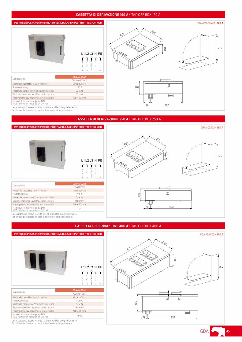
CASSETTA DI DERIVAZIONE 160 A • TAP OFF BOX 160 A
Codice/CodeGDA 4 / GDA 5
GDA401602
Materiale cassetta/Tap off material Metallo/Steel
Portata/Rating 160 A
Materiale conduttore/Conductor material Cu + Ag
Sezione massima cavo/Max cable sectlon 70 mm2
Foro ingresso cavi max/Max. entrance cable 170 x 60 mmN. moduli interruttore guida DIN MCB number of modules on DIN rail 8
La cassetta può essere inserita su entrambi i lati di ogni elemento.Tap off can be inserted on each side of every straight element.
GDA 401602 - 160 A
420290
140 535
140
78 342
30
IP55 PREDISPOSTA PER INTERRUTTORE MODULARE • IP55 PREFITTED FOR MCB
GDA 45
CASSETTA DI DERIVAZIONE 250 A • TAP OFF BOX 250 A
Codice/CodeGDA 4 / GDA 5GDA402502
Materiale cassetta/Tap off material Metallo/Steel
Portata/Rating 250 A
Materiale conduttore/Conductor material Cu + Ag
Sezione massima cavo/Max cable sectlon 150 mm2
Foro ingresso cavi max/Max. entrance cable 170 x 60 mmN. moduli interruttore guida DIN MCB number of modules on DIN rail 12
La cassetta può essere inserita su entrambi i lati di ogni elemento.Tap off can be inserted on each side of every straight element.
GDA 402502 - 250 AIP55 PREDISPOSTA PER INTERRUTTORE MODULARE • IP55 PREFITTED FOR MCB
CASSETTA DI DERIVAZIONE 400 A • TAP OFF BOX 400 A
Codice/CodeGDA 4 / GDA 5GDA404002
Materiale cassetta/Tap off material Metallo/Steel
Portata/Rating 400 A
Materiale conduttore/Conductor material Cu + Ag
Sezione massima cavo/Max cable sectlon 185 mm2
Foro ingresso cavi max/Max. entrance cable 170 x 60 mmN. moduli interruttore guida DIN MCB number of modules on DIN rail 12+12
La cassetta può essere inserita su entrambi i lati di ogni elemento.Tap off can be inserted on each side of every straight element.
GDA 404002 - 400 AIP55 PREDISPOSTA PER INTERRUTTORE MODULARE • IP55 PREFITTED FOR MCB
560
CASSETTA DI DERIVAZIONE 160 A • TAP OFF BOX 160 A
Codice/CodeGDA 4 / GDA 5
GDA401602M12
Materiale cassetta/Tap off material Metallo/Steel
Portata/Rating 160 A
Materiale conduttore/Conductor material Cu + Ag
Sezione massima cavo/Max cable sectlon 70 mm2
Foro ingresso cavi max/Max. entrance cable 170 x 60 mmN. moduli interruttore guida DIN MCB number of modules on DIN rail 12
La cassetta può essere inserita su entrambi i lati di ogni elemento.Tap off can be inserted on each side of every straight element.
GDA 401602M12 - 160 AIP55 PREDISPOSTA PER INTERRUTTORE MODULARE • IP55 PREFITTED FOR MCB
420290
140 535
140
78 342
30
300
140
675
140 30
78 482
677
300
200
855
200
30 30
78 599
GDA46
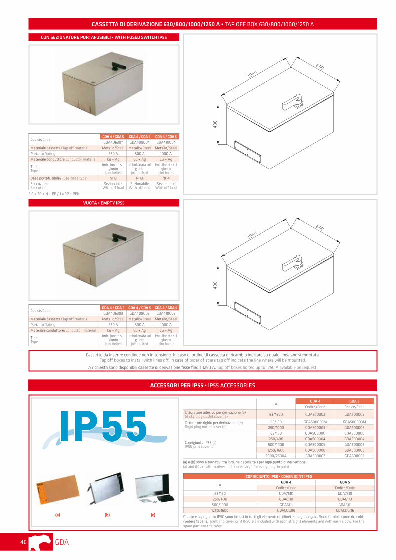
CASSETTA DI DERIVAZIONE 630/800/1000/1250 A • TAP OFF BOX 630/800/1000/1250 A
Codice/CodeGDA 4 / GDA 5 GDA 4 / GDA 5 GDA 4 / GDA 5GDA40630* GDA40800* GDA41000*
Materiale cassetta/Tap off material Metallo/Steel Metallo/Steel Metallo/Steel
Portata/Rating 630 A 800 A 1000 A
Materiale conduttore Conductor material Cu + Ag Cu + Ag Cu + Ag
TipoType
Imbullonata sul giunto
Joint bolted
Imbullonata sul giunto
Joint bolted
Imbullonata sul giunto
Joint bolted Base portafusibile/Fuse-base type NH3 NH3 NH4EsecuzioneExecution
SezionabileWith off load
SezionabileWith off load
SezionabileWith off load
* 0 = 3P + N + PE / 1 = 3P + PEN
Codice/CodeGDA 4 / GDA 5 GDA 4 / GDA 5 GDA 4 / GDA 5GDA406303 GDA408003 GDA410003
Materiale cassetta/Tap off material Metallo/Steel Metallo/Steel Metallo/Steel
Portata/Rating 630 A 800 A 1000 A
Materiale conduttore/Conductor material Cu + Ag Cu + Ag Cu + Ag
TipoType
Imbullonata sul giunto
Joint bolted
Imbullonata sul giunto
Joint bolted
Imbullonata sul giunto
Joint bolted
CON SEZIONATORE PORTAFUSIBILI • WITH FUSED SWITCH IP55
VUOTA • EMPTY IP55
Cassette da inserire con linee non in tensione. In caso di ordine di cassetta di ricambio indicare su quale linea andrà montata.Tap off boxes to install with lines off. In case of order of spare tap off indicate the line where will be mounted.
A richiesta sono disponibili cassette di derivazione fisse fino a 1250 A. Tap off boxes bolted up to 1250 A available on request.
ACCESSORI PER IP55 • IP55 ACCESSORIES
(a) (b) (c)
AGDA 4 GDA 5
Codice/Code Codice/CodeOtturatore adesivo per derivazione (a)Sticky plug outlet cover (a) 63/1600 GDA500002 GDA500002
Otturatore rigido per derivazione (b)Rigid plug outlet cover (b)
63/160 GDA500003M GDA500003M
250/1000 GDA500003 GDA500003
Coprigiunto IP55 (c)IP55 joint cover (c)
63/160 GDA500000 GDA500000
250/400 GDA500004 GDA500004
500/1000 GDA500005 GDA500005
1250/1600 GDA500006 GDA500006
2000/2500A GDA500007 GDA500007
(a) e (b) sono alternativi tra loro, ne necessita 1 per ogni punto di derivazione.(a) and (b) are alternatives. It is necessary 1 for every plug-in point.
COPRIGIUNTO IP50 • COVER JOINT IP50
AGDA 4 GDA 5
Codice/Code Codice/Code
63/160 GDA7510 GDA7510
250/400 GDA6110 GDA6110
500/1000 GDA6111 GDA6111
1250/1600 GDACOGI16 GDACOGI16
Giunto e coprigiunto IP50 sono inclusi in tutti gli elementi rettilinei e in ogni angolo. Sono fornibili come ricambi (vedere tabella). Joint and cover joint IP50 are included with each straight elements and with each elbow. For the spare part see the table.
GDA 47
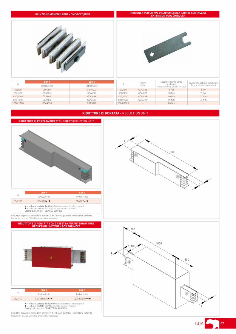
AGDA 4 GDA 5
Codice/Code Codice/Code
63/2500 GDAREDBOX/n GDAREDBOX/n
= indicare portata da ridurre/indicate current to be reduced = indicare portata ridotta/indicate current reducedEsempio/Example = GDAREDBOX 800/400
I riduttori di portata secondo le norme CEI 64/8 sono quotati e realizzati su richiesta. Reduction unit as CEI 64/8 are made on request.
AGDA 4 GDA 5
Codice/Code Codice/Code
63/2500 GDARED / GDARED /
= indicare portata da ridurre/indicate current to be reduced = indicare portata ridotta/indicate current reducedEsempio/Example = GDARED 800/400
I riduttori di portata secondo le norme CEI 64/8 sono quotati e realizzati su richiesta. Reduction unit as CEI 64/8 are made on request.
RIDUTTORE DI PORTATA DIRETTO • DIRECT REDUCTION UNIT
RIDUTTORE DI PORTATA CON CASSETTA PER INTERRUTTORE REDUCTION UNIT WITH BOX FOR MCCB
1000
L
L
300
1000
300
400
L
L
RIDUTTORE DI PORTATA • REDUCTION UNIT
AGDA 4 GDA 5
Codice/Code Codice/Code
63/160 GDA7514 GDA5G02
250/400 GDA6014 GDA6135
500/1000 GDA6015 GDA6136
1250/1600 GDA4G16 GDA5G162000/2500 GDA4G20 GDA5G20
A CodiceCode
Coppia serraggio senza prolunga
Torque without extension tool
Coppia serraggio con prolunga Torque with extension tool
63/160 GDA6199 15 Nm 8 Nm
250/400 GDA6129 30 Nm 15 Nm
500/1000 GDA6129 40 Nm 22 Nm
1250/1600 GDA6129 55 Nm 32 Nm
2000/2500 - 80 Nm -
PROLUNGA PER CHIAVE DINAMOMETRICA (COPPIE SERRAGGIO)EXTENSION TOOL (TORQUE) GIUNZIONE MONOBULLONE • ONE-BOLT JOINT
N
N
N
N
GDA48
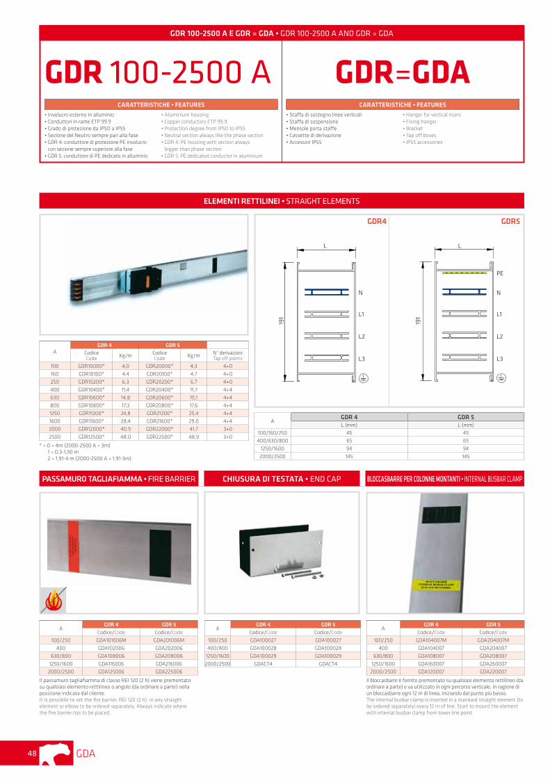
GDR 100-2500 A E GDR = GDA • GDR 100-2500 A AND GDR = GDA
GDR 100-2500 ACARATTERISTICHE • FEATURES
• Involucro esterno in alluminio• Conduttori in rame ETP 99.9• Grado di protezione da IPSO a IP55• Sezione del Neutro sempre pari alla fase• GDR 4: conduttore di protezione PE involucro
con sezione sempre superiore alla fase• GDR 5: conduttore di PE dedicato in alluminio
• Aluminium housing• Copper conductors ETP 99.9• Protection degree from IP50 to IP55• Neutral section always like the phase section• GDR 4: PE housing with section always
bigger than phase section• GDR 5: PE dedicated conductor in aluminium
GDR=GDACARATTERISTICHE • FEATURES
• Staffa di sostegno linee verticali• Staffa di sospensione• Mensole porta staffe• Cassette di derivazione• Accessori IP55
• Hanger for vertical risers• Fixing hanger• Bracket• Tap off boxes• IP55 accessories
AGDR 4 GDR 5
CodiceCode Kg/m Codice
Code Kg/m N° derivazioniTap off points
100 GDR10000* 4,0 GDR20000* 4,3 4+0
160 GDR10100* 4,4 GDR20100* 4,7 4+0
250 GDR10200* 6,3 GDR20200* 6,7 4+0
400 GDR10400* 11,4 GDR20400* 11,7 4+4
630 GDR10600* 14,8 GDR20600* 15,1 4+4
800 GDR10800* 17,3 GDR20800* 17,6 4+4
1250 GDR11200* 24,8 GDR21200* 25,4 4+4
1600 GDR11600* 28,4 GDR21600* 29,0 4+4
2000 GDR12000* 40,9 GDR22000* 41,7 3+0
2500 GDR12500* 48,0 GDR22500* 48,9 3+0
* = 0 = 4m (2000-2500 A = 3m) 1 = 0,3-1,90 m 2 = 1,91-4 m (2000-2500 A = 1,91-3m).
AGDR 4 GDR 5L (mm) L (mm)
100/160/250 45 45
400/630/800 65 65
1250/1600 94 94
2000/2500 145 145
L
191
N
L1
L2
L3
N
L1
L2
L3
191
L
PE
GDR4 GDR5
ELEMENTI RETTILINEI • STRAIGHT ELEMENTS
PASSAMURO TAGLIAFIAMMA • FIRE BARRIER CHIUSURA DI TESTATA • END CAP BLOCCASBARRE PER COLONNE MONTANTI • INTERNAL BUSBAR CLAMP
AGDR 4 GDR 5
Codice/Code Codice/Code
100/250 GDA104007M GDA204007M
400 GDA104007 GDA204007
630/800 GDA108007 GDA208007
1250/1600 GDA160007 GDA260007
2000/2500 GDA120007 GDA220007
Il bloccasbarre è fornito premontato su qualsiasi elemento rettilineo (da ordinare a parte) e va utilizzato in ogni percorso verticale, in ragione di un bloccasbarre ogni 12 m di linea, iniziando dal punto più basso. The internaI busbar clamp is inserted in a standard straight element (to be ordered separately) every 12 m of line. Start to mount the element with internaI busbar clamp from lower line point.
AGDR 4 GDR 5
Codice/Code Codice/Code
100/250 GDA100027 GDA100027
400/800 GDA100028 GDA100028
1250/1600 GDA100029 GDA100029
2000/2500 GDACT4 GDACT4
AGDR 4 GDR 5
Codice/Code Codice/Code
100/250 GDA101006M GDA201006M
400 GDA102006 GDA202006
630/800 GDA108006 GDA208006
1250/1600 GDA116006 GDA216006
2000/2500 GDA125006 GDA225006
Il passamuro tagliafiamma di classe REI 120 (2 h) viene premontato su qualsiasi elemento rettilineo o angolo (da ordinare a parte) nella posizione indicata dal cliente. It is possibile to set the fire barrier, REI 120 (2 h), in any straight element or elbow to be ordered separately. Always indicate where the fire barrier has to be piaced.
GDA 49
A
GDR 4 GDR 5DX SX DX SX
Codice/Code Codice/Code
100/160/250 GDR100111M GDR100109M GDR200111M GDR200109M
400 GDR100111 GDR100109 GDR200111 GDR200109
630/800 GDR100112 GDR100110 GDR200112 GDR200110
1250/1600 GDR116122 GDR116120 GDR216122 GDR216120
2000/2500 GDR120122 GDR120120 GDR220122 GDR220120
In ogni elemento a “T” è incluso 1 giunto.In every “T” elbow is included 1 joint.
Per i disegni tecnici vedi pagina 34For technical drawings see page 34
A
GDR 4 GDR 5DX SX DX SX
Codice/Code Codice/Code
100/160/250 GDR100030M GDR100032M GDR200030M GDR200032M
400 GDR100030 GDR100032 GDR200030 GDR200032
630/800 GDR100031 GDR100033 GDR200031 GDR200033
1250/1600 GDR100051 GDR1OO053 GDR200051 GDR200053
2000/2500 GDR100061 GDR100063 GDR200061 GDR200063
Per i disegni tecnici vedi pagina 40For technical drawings see page 40
AGDR 4 GDR 5CodiceCode
CodiceCode
100/250 GDR7514 GDR5G02
400/800 GDR6014 GDR6135
1250/1600 GDR6015 GDR6136
2000/2500 GDR4G16 GDR5G16
ELEMENTI A “T” • “T” ELEMENTS
ELEMENTO TERMINALE QUADRO • SWITCHBOARD FEED UNITGIUNZIONE MONOBULLONE • ONE-BOLT JOINT
A
GDR 4 GDR 5DX SX DX SX
Codice/Code Codice/Code
100/160/250 GDR100102M GDR100101M GDR200102M GDR200101M
400 GDR100102 GDR100101 GDR200102 GDR200101
630/800 GDR100106 GDR100105 GDR200106 GDR200105
1250 GDR100116 GDR100115 GDR200116 GDR200115
1600 GDR100116 GDR100115 GDR200116 GDR200115
2000/2500 GDR120116 GDR120115 GDR220116 GDR220115
Il giunto è sempre incluso in ogni elemento.The joint is always included in each element.
Per i disegni tecnici vedi pagina 33For technical drawings see page 33
ANGOLI ORIZZONTALI • HORIZONTAL ELBOWS ANGOLI VERTICALI • VERTICAL ELBOWS
A
GDR 4 GDR 5DX SX DX SX
Codice/Code Codice/Code
100/160/250 GDR100021M GDR100020M GDR200021M GDR200020M
400 GDR100021 GDR100020 GDR200021 GDR200020
630/800 GDR100023 GDR100022 GDR200023 GDR200022
1250/1600 GDR100043 GDR100042 GDR200043 GDR200042
2000/2500 GDR120043 GDR120042 GDR220043 GDR220042
Foro passaggio cavi: Cables entrance: 100-250A: Ø 46 - 400-800 A: 75x200 mm - 1250-2500 A: 364-175 mm
ALIMENTAZIONE DI TESTATA IP55 • END FEED UNIT IP55 ALIMENTAZIONE DI TESTATA CON INTERRUTTORE SEZIONATORE IP55 • END FEED UNIT WITH SWITCH IP55
ALIMENTAZIONE INTERMEDIA IP55 CENTRE FEED UNIT IP55
RIDUTTORE DI PORTATA DIRETTO DIRECT REDUCTION UNIT
A
GDR 4 GDR 5DX SX DX SX
Codice/Code Codice/Code
100/160/250 GDR100104M GDR100103M GDR200104M GDR200103M
400 GDR100104 GDR100103 GDR200104 GDR200103
630/800 GDR100108 GDR100107 GDR200108 GDR200107
1250 GDR100118 GDR100117 GDR200118 GDR200117
1600 GDR100118 GDR100117 GDR200118 GDR200117
2000/2500 GDR120118 GDR120117 GDR200118 GDR200117
Il giunto è sempre incluso in ogni elemento.The joint is always included in each element.
Per i disegni tecnici vedi pagina 33For technical drawings see page 33
A
GDR 4 GDR 5DX SX DX SX
Codice/Code Codice/Code
100/160/250 GDR10*003 GDR10*004 GDR20*003 GDR20*004
400 GDR104003 GDR104004 GDR204003 GDR204004
630/800 GDR10*003 GDR10*004 GDR20*003 GDR20*004
1250/1600 GDR11*003 GDR11*004 GDR21*003 GDR21*004
Foro passaggio cavi: Cables entrance: 100-250A: Ø 46 - 400-800 A: 75x200 mm - 1250-1600 A: 364-175 mm
A
GDR 4 GDR 5
Codice/Code Codice/Code
100/160/250 GDR100024M GDR200024M
400 GDR100024 GDR200024
630/800 GDR100025 GDR200025
1250/1600 GDR100045 GDR200045
2000/2500 GDR100055 GDR200055
Foro passaggio cavi: Cables entrance: 100-250A: Ø 46 - 400-800 A: 75x200 mm - 1250-2500 A: 364-175 mm
AGDA 4 GDA 5
Codice/Code Codice/Code
63/2500 GDAREDBOX/n GDAREDBOX/n
= indicare portata da ridurre/indicate current to be reduced = indicare portata ridotta/indicate current reducedEsempio/Example = GDAREDBOX 800/400
I riduttori di portata secondo le norme CEI 64/8 sono quotati e realizzati su richiesta. Reduction unit as CEI 64/8 are made on request.
GDA50
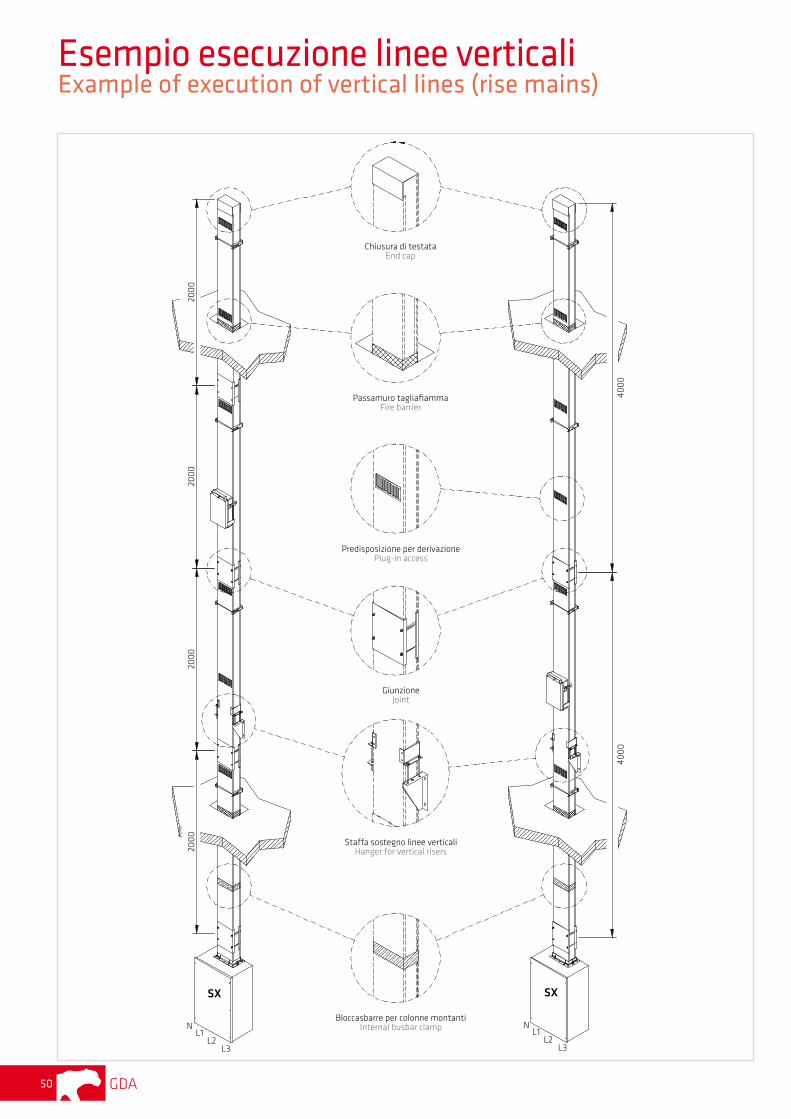
Chiusura di testataEnd cap
Passamuro tagliafiammaFire barrier
GiunzioneJoint
Staffa sostegno linee verticaliHanger for vertical risers
Bloccasbarre per colonne montantiInternal busbar clamp
Predisposizione per derivazionePlug-in access
2000
2000
2000
2000
4000
4000
SX
NL1
L2L3
SX
NL1
L2L3
Esempio esecuzione linee verticali Example of execution of vertical lines (rise mains)
GDA 51
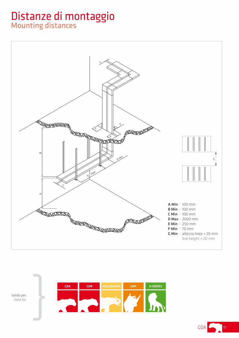
A Min - 100 mm B Min - 100 mm C Min - 100 mm D Max - 2000 mm E Min - 250 mm F Min - 70 mmG Min - altezza linea + 20 mm line height + 20 mm
Distanze di montaggio Mounting distances
Valido per:Valid for:
GDA GDR ISOLSBARRA GMT K-SERIES
G
GDA52
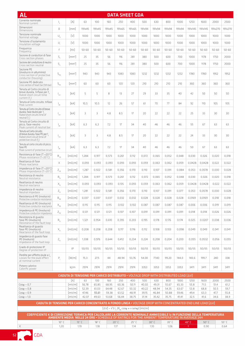
DATA SHEET GDACorrente nominaleNominal current I
n[A] 63 100 160 250 400 500 630 800 1000 1250 1600 2000 2500
DimensioniDimensions D [mm] 191x45 191x45 191x45 191x65 191x65 191x94 191x94 191x94 191x94 191x145 191x145 191x270 191x270
Tensione nominaleNominal voltage U
e[V] 1000 1000 1000 1000 1000 1000 1000 1000 1000 1000 1000 1000 1000
Tensione d’isolamentoInsulation voltage U
i[V] 1000 1000 1000 1000 1000 1000 1000 1000 1000 1000 1000 1000 1000
FrequenzaFrequency f [Hz] 50-60 50-60 50-60 50-60 50-60 50-60 50-60 50-60 50-60 50-60 50-60 50-60 50-60
Sezione di conduttori di faseCross section phases S
f[mm2] 25 35 56 116 281 380 500 600 700 1000 1178 1750 2000
Sezione del conduttore di neutroCross section neutral S
n[mm2] 25 35 56 116 281 380 500 600 700 1000 1178 1750 2000
Sezione PE(involucro in alluminio)Cross section of protective conductor (housing)
SPE
[mm2] 943 943 943 1083 1083 1232 1232 1232 1232 1780 1780 1952 1952
Sezione PE dedicatoCross section of heart bar (5th bar) S
PE[mm2] 60 60 60 120 120 210 210 210 210 360 360 360 360
Tenuta al Corto circuito di breve durata, trifase per 1
sRated short circuit time current (1
s)
Icw
[kA] 5 5 8 13 27 29 33 35 40 42 50 50 50
Tenuta al Corto circuito, trifase Peak current I
pk[kA] 10,5 10,5 12 26 57 61 70 77 84 92 110 105 105
Tenuta al Corto circuito di breve durata, fase neutro per 1
sRated short circuits time of neutral (1
s)
Icw
[kA] 3 3 4,8 8,5 17 20 22 22 22 25 33 30 30
Tenuta al Corto circuito di picco, fase-neutroPeak current of neutral bar
Ipk
[kA] 6,3 6,3 7,2 17 34 40 46 46 46 55 67 63 63
Tenuta al Corto circuitodi breve durata, fase PE per 1
s
Rated short circuit time of protective circuit (1
s)
Icw
[kA] 3 3 4,8 8,5 17 20 22 22 22 24 33 30 30
Tenuta al corto circuito di picco, fase PEPeak current of protective circuit
Ipk
[kA] 6,3 6,3 7,2 17 34 40 46 46 46 50 67 63 63
Resistenza di fase (T =20°C) Phase resistance (T=20°C) R
20[mΩ/m] 1,284 0,917 0,573 0,261 0,112 0,072 0,065 0,052 0,048 0,030 0,026 0,020 0,018
Reattanza di fasePhase reactance X [mΩ/m] 0,093 0,093 0,093 0,093 0,093 0,059 0,063 0,062 0,059 0,0428 0,0428 0,022 0,022
Impedenza di fase (T =20°C) Phase Impendance (T=20°C) Z
20[mΩ/m] 1,287 0,922 0,581 0,356 0,170 0,110 0,107 0,091 0,084 0,053 0,0578 0,030 0,028
Resistenza di neutro Neutral resistance R
N[mΩ/m] 1,284 0,917 0,573 0,261 0,112 0,072 0,065 0,052 0,048 0,030 0,026 0,020 0,018
Reattanza di neutro Neutral reactance X
N[mΩ/m] 0,093 0,093 0,093 0,135 0,093 0,059 0,063 0,062 0,059 0,0428 0,0428 0,022 0,022
Impedenza di neutro Neutral impedace Z
N[mΩ/m] 1,281 0,922 0,581 0,356 0,170 0,110 0,107 0,091 0,077 0,053 0,0578 0,030 0,028
Resistenza di PE (involucro)Protective conductor resistance R
PE[mΩ/m] 0,037 0,037 0,037 0,032 0,032 0,028 0,028 0,028 0,028 0,0169 0,0169 0,018 0,018
Reattanza di PE (involucro) Protective conductor reactance X
PE[mΩ/m] 0,115 0,115 0,115 0,102 0,102 0,087 0,087 0,087 0,087 0,006 0,006 0,019 0,019
Impedenza di PE (involucro) Protective conductor impedance Z
PE[mΩ/m] 0,121 0,121 0,121 0,107 0,107 0,091 0,091 0,091 0,091 0,018 0,018 0,026 0,026
Resistenza di guastofase PE (involucro) Resistance of the fault loop
RO
[mΩ/m] 1,321 0,954 0,610 0,395 0,203 0,195 0,178 0,176 0,174 0,025 0,0207 0,038 0,036
Reattanza di guastofase PE (involucro) Reactance of the fault loop
XO
[mΩ/m] 0,208 0,208 0,208 0,117 0,116 0,112 0,108 0,103 0,098 0,049 0,049 0,041 0,041
Impedenza di guasto fase PE (involucro) Impedance of the fault loop
ZO
[mΩ/m] 1,338 0,976 0,644 0,412 0,234 0,224 0,208 0,204 0,200 0,055 0,0532 0,056 0,055
Grado di protezione IPDegree of protection IP IP 50/55 50/55 50/55 50/55 50/55 50/55 50/55 50/55 50/55 50/55 50/55 50/55 50/55
Perdite per effetto Joule a In
Losses for the Joule effectat nominal current
Pj
[W/m] 15,3 27,5 44 48,94 53,76 54,00 77,40 99,20 144,0 140,6 199,7 240 338
Potere caloricoCalorific power kJ/m 2974 2974 2974 2974 2974 3353 3353 3353 3353 3411 3411 3411 3411
CADUTA DI TENSIONE PER CARICO DISTRIBUITO • VOLTAGE DROP WITH DISTRIBUTED LOAD [∆V]
[A] 63 100 160 250 400 500 630 800 1000 1250 1600 2000 2500
Cosϕ = 0,7 [mV/m] 56,78 65,85 68,95 60,36 50,11 40,02 49,31 55,67 65,33 55,8 71,5 51,4 61,2
Cosϕ = 0,8 [mV/m] 52,39 61,03 64,48 62,67 50,32 40,22 48,94 54,35 63,67 53,8 68,8 50,5 59,7
Cosϕ = 0,9 [mV/m] 47,46 55,61 59,38 63,52 48,91 39,15 46,84 50,88 59,46 49,4 63,3 47,7 55,8
Cosϕ = 1,0 [mV/m] 42,07 49,63 53,68 56,44 38,75 31,14 35,42 35,75 41,41 32,5 41,6 34,6 38,9
COEFFICIENTE K DI CORREZIONE TERMICA PER CALCOLARE LA CORRENTE NOMINALE AMMISSIBILE lz IN FUNZIONE DELLA TEMPERATURA AMBIENTE MEDIA NELLE 24 ORE • SCHEDULE OF RATINGS FOR THE AMBIENT TEMPERATURE IN AVERAGE 24H
10° C 15° C 18° C 20° C 25° C 30° C 35° C 43° C 50° C 55° C
K 1,20 1,19 1,18 1,17 1,14 1,10 1,06 1 0,90 0,64
CADUTA DI TENSIONE PER CARICO CONCENTRATO A FONDO LINEA • VOLTAGE DROP WITH CONCENTRATED END LINE LOAD [∆V]
[∆V] = √3 In (R
θ1 cosϕ + x senϕ) [mV/m]
AL
GDA 53
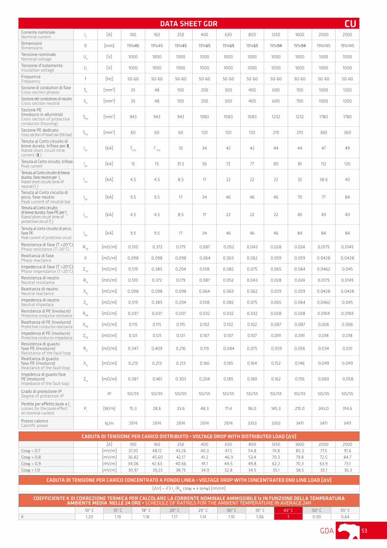
DATA SHEET GDRCorrente nominaleNominal current I
n[A] 100 160 250 400 630 800 1250 1600 2000 2500
DimensioniDimensions D [mm] 191x45 191x45 191x45 191x65 191x65 191x65 191x94 191x94 191x145 191x145
Tensione nominaleNominal voltage U
e[V] 1000 1000 1000 1000 1000 1000 1000 1000 1000 1000
Tensione d’isolamentoInsulation voltage U
i[V] 1000 1000 1000 1000 1000 1000 1000 1000 1000 1000
FrequenzaFrequency f [Hz] 50-60 50-60 50-60 50-60 50-60 50-60 50-60 50-60 50-60 50-60
Sezione di conduttori di faseCross section phases S
f[mm2] 35 48 100 200 300 400 600 700 1000 1200
Sezione del conduttore di neutroCross section neutral S
n[mm2] 35 48 100 200 300 400 600 700 1000 1200
Sezione PE(involucro in alluminio)Cross section of protective conductor (housing)
SPE
[mm2] 943 943 943 1083 1083 1083 1232 1232 1780 1780
Sezione PE dedicatoCross section of heart bar (5th bar) S
PE[mm2] 60 60 60 120 120 120 210 210 360 360
Tenuta al Corto circuito di breve durata, trifase per 3
sRated short circuit time current (3
s)
I3S
[kA] 7(1S)
7 (1S)
10 34 42 42 44 44 47 49
Tenuta al Corto circuito, trifase Peak current I
pk[kA] 15 15 31,5 56 72 77 80 81 112 126
Tenuta al Corto circuito di breve durata, fase neutro per 1
sRated short circuits time of neutral (1
s)
Icw
[kA] 4,5 4,5 8,5 17 22 22 22 32 38,6 40
Tenuta al Corto circuito di picco, fase-neutroPeak current of neutral bar
Ipk
[kA] 9,5 9,5 17 34 46 46 46 70 77 84
Tenuta al Corto circuitodi breve durata, fase PE per 1
s
Rated short circuit time of protective circuit (1
s)
Icw
[kA] 4,5 4,5 8,5 17 22 22 22 40 40 40
Tenuta al corto circuito di picco, fase PEPeak current of protective circuit
Ipk
[kA] 9,5 9,5 17 34 46 46 46 84 84 84
Resistenza di fase (T =20°C) Phase resistance (T=20°C) R
20[mΩ/m] 0,510 0,372 0,179 0,087 0,052 0,043 0,028 0,024 0,0175 0,0145
Reattanza di fasePhase reactance X [mΩ/m] 0,098 0,098 0,098 0,064 0,063 0,062 0,059 0,059 0,0428 0,0428
Impedenza di fase (T =20°C) Phase Impendance (T=20°C) Z
20[mΩ/m] 0,519 0,385 0,204 0,108 0,082 0,075 0,065 0,064 0,0462 0,045
Resistenza di neutro Neutral resistance R
N[mΩ/m] 0,510 0,372 0,179 0,087 0,052 0,043 0,028 0,024 0,0175 0,0145
Reattanza di neutro Neutral reactance X
N[mΩ/m] 0,098 0,098 0,098 0,064 0,063 0,062 0,059 0,059 0,0428 0,0428
Impedenza di neutro Neutral impedace Z
N[mΩ/m] 0,519 0,385 0,204 0,108 0,082 0,075 0,065 0,064 0,0462 0,045
Resistenza di PE (involucro)Protective conductor resistance R
PE[mΩ/m] 0,037 0,037 0,037 0,032 0,032 0,032 0,028 0,028 0,0169 0,0169
Reattanza di PE (involucro) Protective conductor reactance X
PE[mΩ/m] 0,115 0,115 0,115 0,102 0,102 0,102 0,087 0,087 0,006 0,006
Impedenza di PE (involucro) Protective conductor impedance Z
PE[mΩ/m] 0,121 0,121 0,121 0,107 0,107 0,107 0,091 0,091 0,018 0,018
Resistenza di guastofase PE (involucro) Resistance of the fault loop
RO
[mΩ/m] 0,547 0,409 0,216 0,119 0,084 0,075 0,059 0,056 0,034 0,031
Reattanza di guastofase PE (involucro) Reactance of the fault loop
XO
[mΩ/m] 0,213 0,213 0,213 0,166 0,165 0,164 0,152 0,146 0,049 0,049
Impedenza di guasto fase PE (involucro) Impedance of the fault loop
ZO
[mΩ/m] 0,587 0,461 0,303 0,204 0,185 0,180 0,162 0,156 0,060 0,058
Grado di protezione IPDegree of protection IP IP 5O/55 5O/55 5O/55 5O/55 5O/55 5O/55 5O/55 5O/55 5O/55 5O/55
Perdite per effetto Joule a In
Losses for the Joule effectat nominal current
Pj
[W/m] 15,3 28,6 33,6 48,3 71,4 96,0 145,3 215,0 243,0 314,6
Potere caloricoCalorific power kJ/m 2974 2974 2974 2974 2974 3353 3353 3411 3411 3411
CADUTA DI TENSIONE PER CARICO DISTRIBUITO • VOLTAGE DROP WITH DISTRIBUTED LOAD [∆V]
[A] 100 160 250 400 630 800 1250 1600 2000 2500
Cosϕ = 0,7 [mV/m] 37,20 48,12 43,26 40,3 47,5 54,8 74,8 85,3 77,5 91,6
Cosϕ = 0,8 [mV/m] 36,82 45,60 42,17 41,2 46,9 53,4 70,3 79,8 72,5 84,7
Cosϕ = 0,9 [mV/m] 34,06 42,63 40,66 41,1 44,5 49,8 62,2 70,3 63,9 73,1
Cosϕ = 1,0 [mV/m] 30,97 39,23 38,75 34,9 32,8 34,5 35,1 38,5 35,1 36,3
CADUTA DI TENSIONE PER CARICO CONCENTRATO A FONDO LINEA • VOLTAGE DROP WITH CONCENTRATED END LINE LOAD [∆V]
[∆V] = √3 In (R
θ1 cosϕ + x senϕ) [mV/m]
COEFFICIENTE K DI CORREZIONE TERMICA PER CALCOLARE LA CORRENTE NOMINALE AMMISSIBILE lz IN FUNZIONE DELLA TEMPERATURA AMBIENTE MEDIA NELLE 24 ORE • SCHEDULE OF RATINGS FOR THE AMBIENT TEMPERATURE IN AVERAGE 24H
10° C 15° C 18° C 20° C 25° C 30° C 35° C 43° C 50° C 55° C
K 1,20 1,19 1,18 1,17 1,14 1,10 1,06 1 0,90 0,64
CU
GDA54
Dichiarazione di conformitàConformity declaration
L’elettrocondotto GDA descritto in questa pubblicazione è conforme alle seguenti norme:
GDA busbar described in this publication complies with the following standards:
IEC61439-1IEC61439-6IEC60529CEI EN50102CEI EN61439-1CEI EN61439-6CEI EN60529
Prove di tipoType test
Tenuta al corto circuitoGrado di protezione degli involucri (codice IP)Resistenza di isolamentoLimite di sovratemperaturaTenuta alla tensione applicataResistenza ai carichi normaliEfficienza del circuito di protezioneDistanze in aria e superficialiGrado di protezione degli involucri (codice IK)
Short-circuit resistanceCasing degree of protection (IP code)Insulation resistanceOverheating limitApplied voltage resistanceResistance to normal loadsProtective circuit efficiencyAir and surface distancesCasing degree of protection (IK code)
CertificazioniCertifications
Per ottenere una copia delle nostre certificazioni:To receive a copy of our certifications:
Il prodotto oggetto di questa dichiarazione ha superato le prove sopra specificate e pertanto il materiale è ammesso alla marcatura:The product object of this declaration exceeds the test types above mentionned and therefore this material is marked:
Rivoli, 07/01/2005 GRAZIADIO & C. S.p.A.
GD
A
GDA 55
Dichiarazione di conformitàConformity declaration
L’elettrocondotto GDR descritto in questa pubblicazione è conforme alle seguenti norme:
GDR busbar described in this publication complies with the following standards:
IEC61439-1IEC61439-6IEC60529CEI EN50102CEI EN61439-1CEI EN61439-6CEI EN60529
Prove di tipoType test
Tenuta al corto circuitoGrado di protezione degli involucri (codice IP)Resistenza di isolamentoLimite di sovratemperaturaTenuta alla tensione applicataResistenza ai carichi normaliEfficienza del circuito di protezioneDistanze in aria e superficialiGrado di protezione degli involucri (codice IK)
Short-circuit resistanceCasing degree of protection (IP code)Insulation resistanceOverheating limitApplied voltage resistanceResistance to normal loadsProtective circuit efficiencyAir and surface distancesCasing degree of protection (IK code)
Il prodotto oggetto di questa dichiarazione ha superato le prove sopra specificate e pertanto il materiale è ammesso alla marcatura:The product object of this declaration exceeds the test types above mentionned and therefore this material is marked:
Rivoli, 07/01/2005 GRAZIADIO & C. S.p.A.
CertificazioniCertifications
Per ottenere una copia delle nostre certificazioni:To receive a copy of our certifications:
GD
R


![IstruzioniCNR_DT208_2011 [Alluminio]](https://static.documenti.site/doc/80x56/55cf9ac9550346d033a363fb/istruzionicnrdt2082011-alluminio.jpg)

