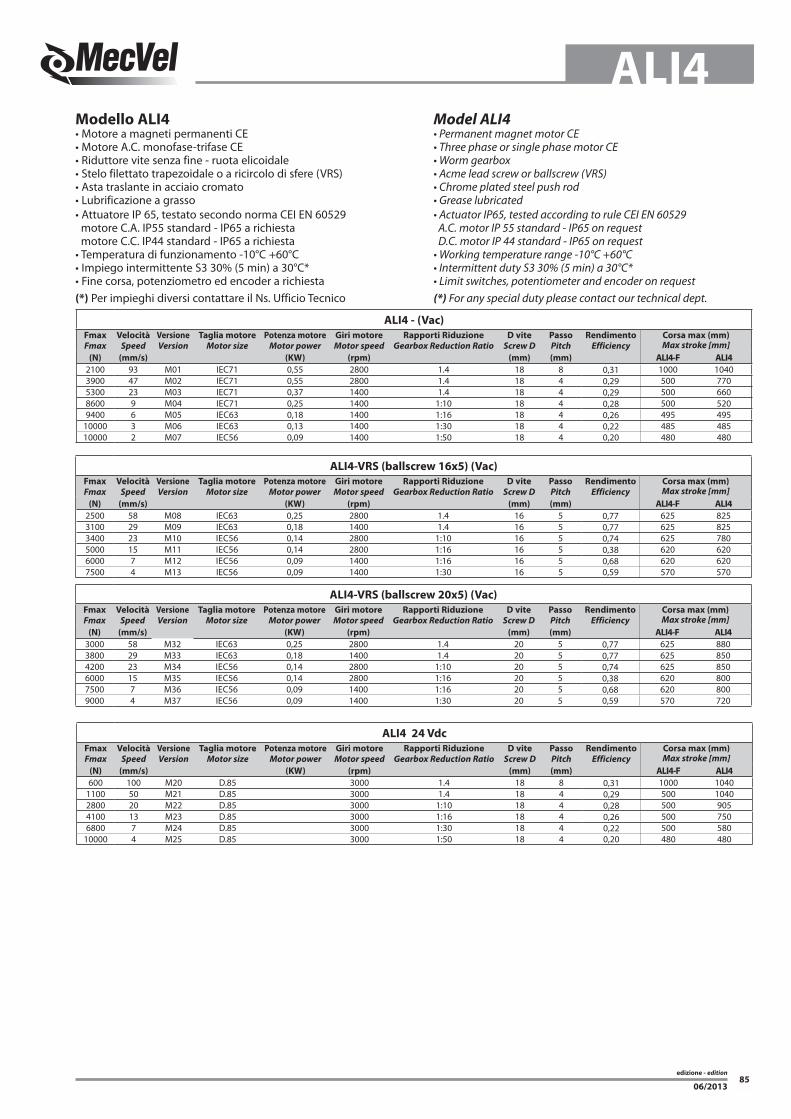
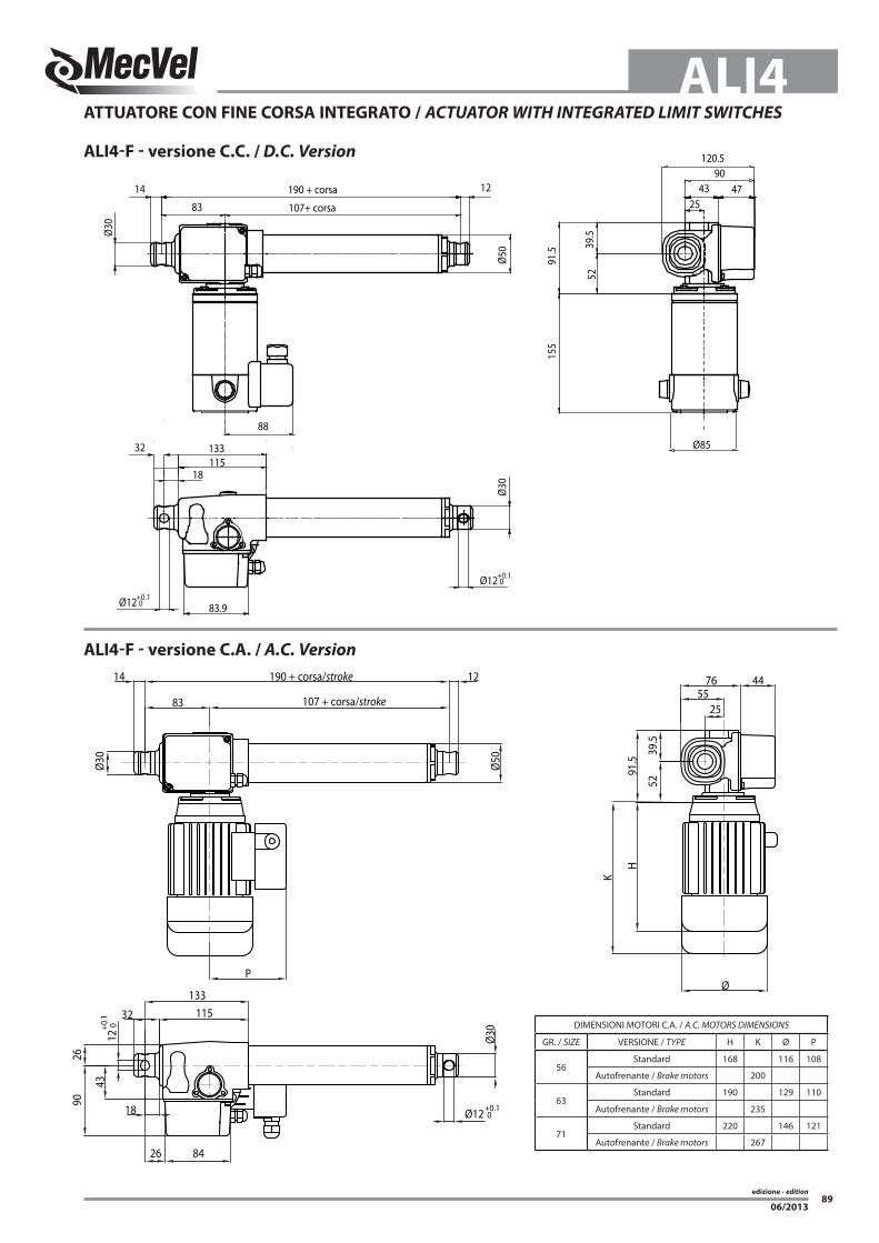
edizione - edition 85 ALI4 06/2013 Modello ALI4 • Motore a magneti permanenti CE • Motore A.C. monofase-trifase CE • Riduttore vite senza fine - ruota elicoidale • Stelo filettato trapezoidale o a ricircolo di sfere (VRS) • Asta traslante in acciaio cromato • Lubrificazione a grasso • Attuatore IP 65, testato secondo norma CEI EN 60529 motore C.A. IP55 standard - IP65 a richiesta motore C.C. IP44 standard - IP65 a richiesta • Temperatura di funzionamento -10°C +60°C • Impiego intermittente S3 30% (5 min) a 30°C* • Fine corsa, potenziometro ed encoder a richiesta (*) Per impieghi diversi contattare il Ns. Ufficio Tecnico Model ALI4 • Permanent magnet motor CE • Three phase or single phase motor CE • Worm gearbox • Acme lead screw or ballscrew (VRS) • Chrome plated steel push rod • Grease lubricated • Actuator IP65, tested according to rule CEI EN 60529 A.C. motor IP 55 standard - IP65 on request D.C. motor IP 44 standard - IP65 on request • Working temperature range -10°C +60°C • Intermittent duty S3 30% (5 min) a 30°C* • Limit switches, potentiometer and encoder on request (*) For any special duty please contact our technical dept. ALI4 - (Vac) Fmax Fmax Velocità Speed Versione Version Taglia motore Motor size Potenza motore Motor power Giri motore Motor speed Rapporti Riduzione Gearbox Reduction Ratio D vite Screw D Passo Pitch Rendimento Efficiency Corsa max (mm) Max stroke [mm] (N) (mm/s) (KW) (rpm) (mm) (mm) ALI4-F ALI4 2100 93 M01 IEC71 0,55 2800 1.4 18 8 0,31 1000 1040 3900 47 M02 IEC71 0,55 2800 1.4 18 4 0,29 500 770 5300 23 M03 IEC71 0,37 1400 1.4 18 4 0,29 500 660 8600 9 M04 IEC71 0,25 1400 1:10 18 4 0,28 500 520 9400 6 M05 IEC63 0,18 1400 1:16 18 4 0,26 495 495 10000 3 M06 IEC63 0,13 1400 1:30 18 4 0,22 485 485 10000 2 M07 IEC56 0,09 1400 1:50 18 4 0,20 480 480 ALI4-VRS (ballscrew 16x5) (Vac) Fmax Fmax Velocità Speed Versione Version Taglia motore Motor size Potenza motore Motor power Giri motore Motor speed Rapporti Riduzione Gearbox Reduction Ratio D vite Screw D Passo Pitch Rendimento Efficiency Corsa max (mm) Max stroke [mm] (N) (mm/s) (KW) (rpm) (mm) (mm) ALI4-F ALI4 2500 58 M08 IEC63 0,25 2800 1.4 16 5 0,77 625 825 3100 29 M09 IEC63 0,18 1400 1.4 16 5 0,77 625 825 3400 23 M10 IEC56 0,14 2800 1:10 16 5 0,74 625 780 5000 15 M11 IEC56 0,14 2800 1:16 16 5 0,38 620 620 6000 7 M12 IEC56 0,09 1400 1:16 16 5 0,68 620 620 7500 4 M13 IEC56 0,09 1400 1:30 16 5 0,59 570 570 ALI4 24 Vdc Fmax Fmax Velocità Speed Versione Version Taglia motore Motor size Potenza motore Motor power Giri motore Motor speed Rapporti Riduzione Gearbox Reduction Ratio D vite Screw D Passo Pitch Rendimento Efficiency Corsa max (mm) Max stroke [mm] (N) (mm/s) (KW) (rpm) (mm) (mm) ALI4-F ALI4 600 100 M20 D.85 3000 1.4 18 8 0,31 1000 1040 1100 50 M21 D.85 3000 1.4 18 4 0,29 500 1040 2800 20 M22 D.85 3000 1:10 18 4 0,28 500 905 4100 13 M23 D.85 3000 1:16 18 4 0,26 500 750 6800 7 M24 D.85 3000 1:30 18 4 0,22 500 580 10000 4 M25 D.85 3000 1:50 18 4 0,20 480 480 ALI4-VRS (ballscrew 20x5) (Vac) Fmax Fmax Velocità Speed Versione Version Taglia motore Motor size Potenza motore Motor power Giri motore Motor speed Rapporti Riduzione Gearbox Reduction Ratio D vite Screw D Passo Pitch Rendimento Efficiency Corsa max (mm) Max stroke [mm] (N) (mm/s) (KW) (rpm) (mm) (mm) ALI4-F ALI4 3000 58 M32 IEC63 0,25 2800 1.4 20 5 0,77 625 880 3800 29 M33 IEC63 0,18 1400 1.4 20 5 0,77 625 850 4200 23 M34 IEC56 0,14 2800 1:10 20 5 0,74 625 850 6000 15 M35 IEC56 0,14 2800 1:16 20 5 0,38 620 800 7500 7 M36 IEC56 0,09 1400 1:16 20 5 0,68 620 800 9000 4 M37 IEC56 0,09 1400 1:30 20 5 0,59 570 720
Transcript
edizione - edition
85
ALI4
06/2013
Modello ALI4• Motore a magneti permanenti CE• Motore A.C. monofase-trifase CE• Riduttore vite senza fine - ruota elicoidale• Stelo filettato trapezoidale o a ricircolo di sfere (VRS)• Asta traslante in acciaio cromato• Lubrificazione a grasso• Attuatore IP 65, testato secondo norma CEI EN 60529 motore C.A. IP55 standard - IP65 a richiesta motore C.C. IP44 standard - IP65 a richiesta• Temperatura di funzionamento -10°C +60°C• Impiego intermittente S3 30% (5 min) a 30°C*• Fine corsa, potenziometro ed encoder a richiesta(*) Per impieghi diversi contattare il Ns. Ufficio Tecnico
Model ALI4• Permanent magnet motor CE• Three phase or single phase motor CE• Worm gearbox• Acme lead screw or ballscrew (VRS)• Chrome plated steel push rod• Grease lubricated• Actuator IP65, tested according to rule CEI EN 60529 A.C. motor IP 55 standard - IP65 on request D.C. motor IP 44 standard - IP65 on request• Working temperature range -10°C +60°C• Intermittent duty S3 30% (5 min) a 30°C*• Limit switches, potentiometer and encoder on request(*) For any special duty please contact our technical dept.
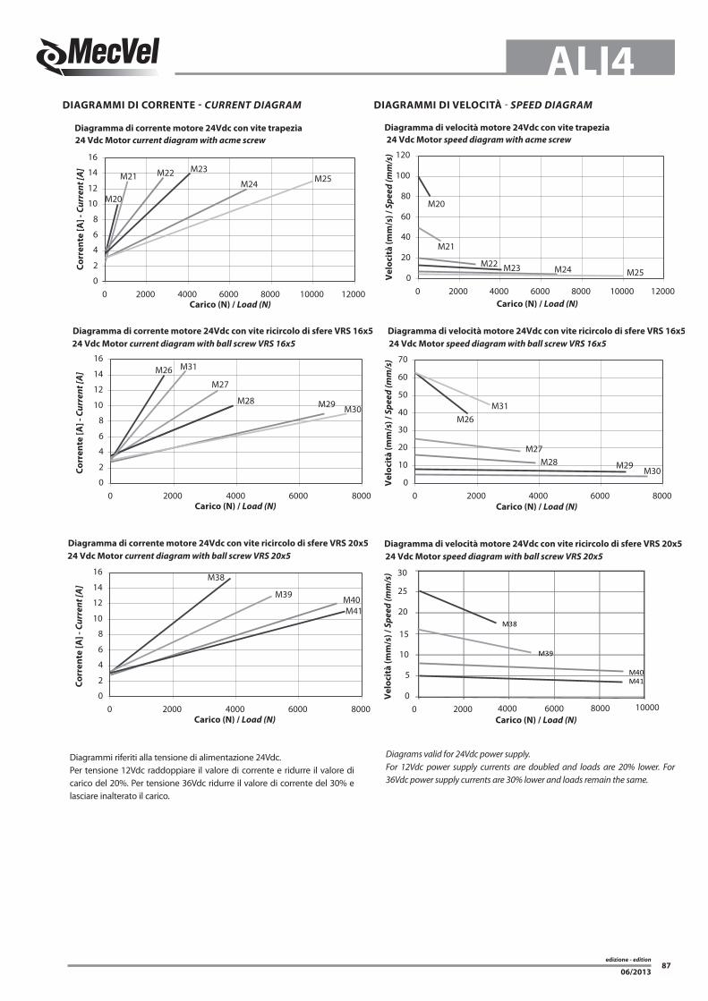
DIAGRAMMI DI CORRENTE - CURRENT DIAGRAM DIAGRAMMI DI VELOCITÀ - SPEED DIAGRAM
Diagrammi riferiti alla tensione di alimentazione 24Vdc.Per tensione 12Vdc raddoppiare il valore di corrente e ridurre il valore di carico del 20%. Per tensione 36Vdc ridurre il valore di corrente del 30% e lasciare inalterato il carico.
Diagrams valid for 24Vdc power supply.For 12Vdc power supply currents are doubled and loads are 20% lower. For 36Vdc power supply currents are 30% lower and loads remain the same.
M22M24
M21
M20
M250
20
40
60
80
100
120
0 2000 4000 6000 8000 10000 120000
2
4
6
8
10
12
14
16
0 2000 4000 6000 8000 10000 12000
M29
0
10
20
30
40
50
60
70
0 2000 4000 6000 80000
2
4
6
8
10
12
14
16
0 2000 4000 6000 8000
Carico (N) / Load (N)
Carico (N) / Load (N)
Carico (N) / Load (N)
Carico (N) / Load (N)
Ve
loc
ità
(m
m/s
) /
Sp
ee
d (
mm
/s)
Ve
loc
ità
(m
m/s
) /
Sp
ee
d (
mm
/s)
Diagramma di corrente motore 24Vdc con vite trapezia
ALI4-VRS (versione 16x5) = + 25 mm ALI4-VRS (versione 20x5) = + 40 mmALI4-VRS-F (versione 16x5) = + 55 mm ALI4-VRS-F (versione 20x5) = + 70 mmALI4-VRS-FCM (versione 16x5) = + 53 mm ALI4-VRS-FCM (versione 20x5) = + 68 mm
AR0 / AR1 = + 15 mm
Protezione Soffietto / Bellows = + 15 mm (escluso versione FCM; per versione FCM contattare MecVel) (excluding FCM version, for version FCM contact MecVel)
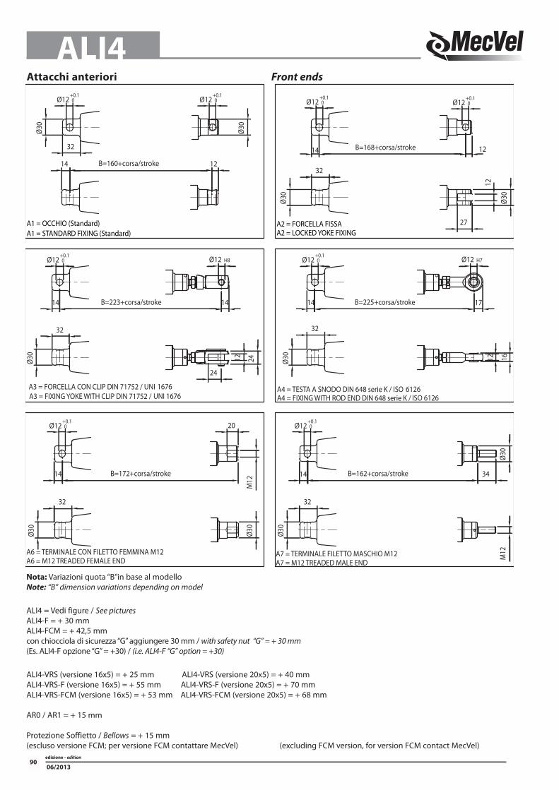
Ø12+0.1 0
A3 = FORCELLA CON CLIP DIN 71752 / UNI 1676A3 = FIXING YOKE WITH CLIP DIN 71752 / UNI 1676
A6 = TERMINALE CON FILETTO FEMMINA M12A6 = M12 TREADED FEMALE END
B=172+corsa/stroke
32
Ø30
14
Ø30
20
M12
B=223+corsa/stroke
B=160+corsa/stroke
Ø12+0.1 0
Ø12+0.1 0
A1 = OCCHIO (Standard)A1 = STANDARD FIXING (Standard)
14
32
Ø30
32
Ø30
Ø12 H8
24
14
12 24
Ø12+0.1 0
Ø30
B=162+corsa/stroke
A4 = TESTA A SNODO DIN 648 serie K / ISO 6126A4 = FIXING WITH ROD END DIN 648 serie K / ISO 6126
Ø12+0.1 0
A7 = TERMINALE FILETTO MASCHIO M12A7 = M12 TREADED MALE END
Ø30
32
14 34
Ø30
B=225+corsa/stroke
B=168+corsa/stroke
27
Ø12+0.1 0
Ø12 H7
Ø30
Ø12+0.1 0
A2 = FORCELLA FISSAA2 = LOCKED YOKE FIXING
Ø30
32
Ø12+0.1 0
32
14
Ø30
12
17
1612
12
14
1214
M12
edizione - edition
91
ALI4
06/2013
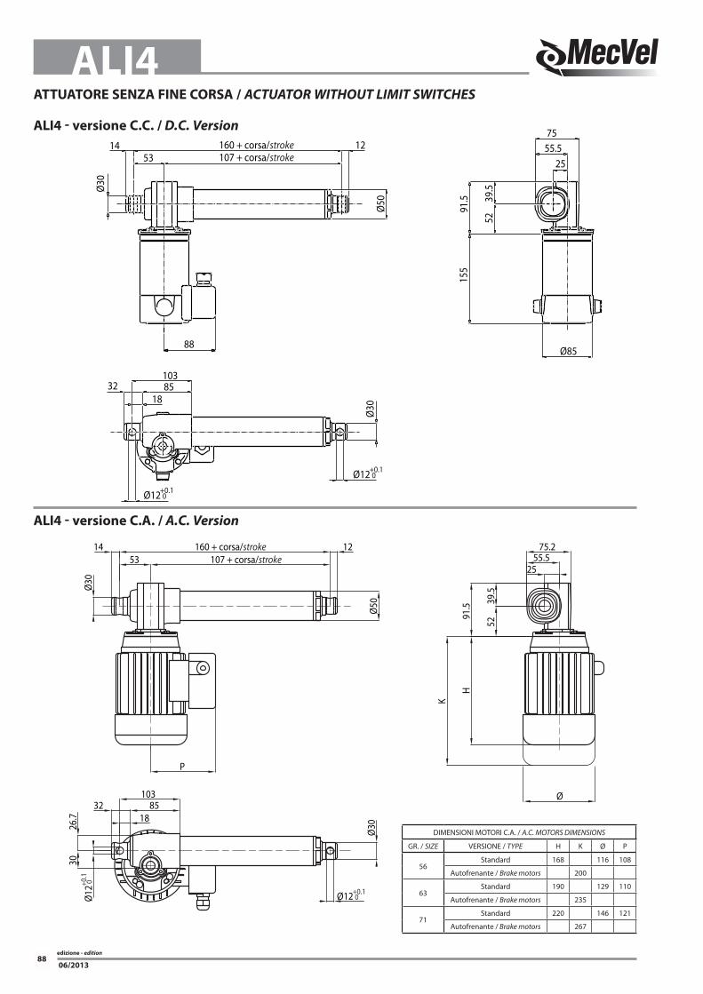
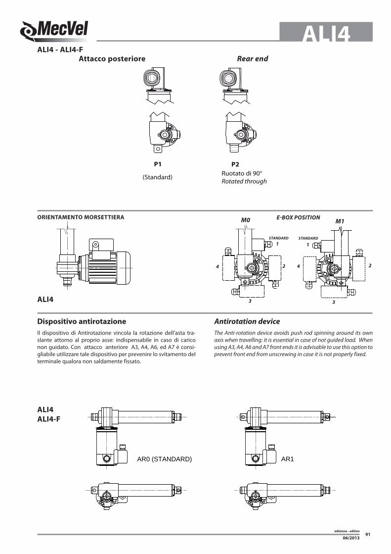
Attacco posteriore
ALI4 - ALI4-F
ALI4
Rear end
P1 P2
Ruotato di 90°Rotated through
(Standard)
ORIENTAMENTO MORSETTIERA E-BOX POSITION
Dispositivo antirotazione
Il dispositivo di Antirotazione vincola la rotazione dell’asta tra-slante attorno al proprio asse: indispensabile in caso di carico non guidato. Con attacco anteriore A3, A4, A6, ed A7 è consi-gliabile utilizzare tale dispositivo per prevenire lo svitamento del terminale qualora non saldamente fissato.
Antirotation device
The Anti-rotation device avoids push rod spinning around its own axis when travelling: it is essential in case of not guided load. When using A3, A4, A6 and A7 front ends it is advisable to use this option to prevent front end from unscrewing in case it is not properly fixed.
ALI4
ALI4-F
AR0 (STANDARD) AR1
M0 M1
1
2
3
4
3
4 2
1
STANDARD STANDARD
edizione - edition
92
ALI4
06/2013
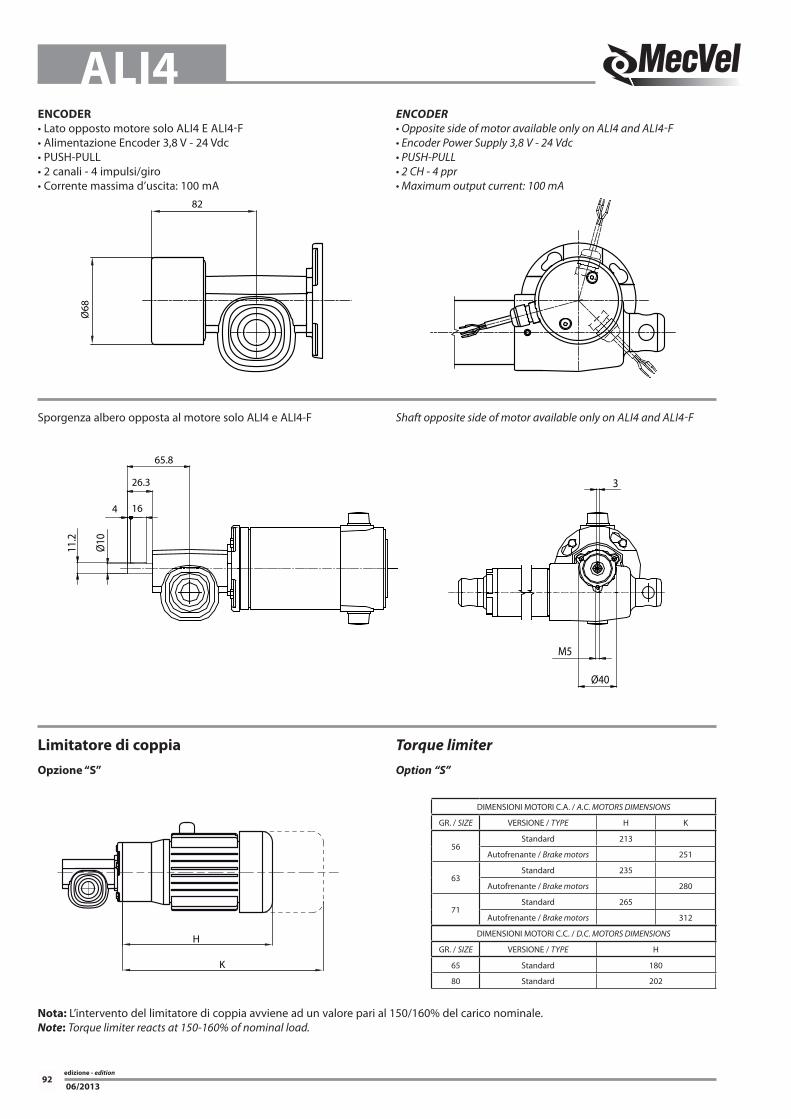
ENCODER
• Lato opposto motore solo ALI4 E ALI4-F• Alimentazione Encoder 3,8 V - 24 Vdc• PUSH-PULL• 2 canali - 4 impulsi/giro• Corrente massima d’uscita: 100 mA
ENCODER
• Opposite side of motor available only on ALI4 and ALI4-F• Encoder Power Supply 3,8 V - 24 Vdc• PUSH-PULL• 2 CH - 4 ppr• Maximum output current: 100 mA
Ø68
82
Limitatore di coppia
Opzione “S”
Torque limiter
Option “S”
K
H
DIMENSIONI MOTORI C.A. / A.C. MOTORS DIMENSIONS
GR. / SIZE VERSIONE / TYPE H K
56Standard 213
Autofrenante / Brake motors 251
63Standard 235
Autofrenante / Brake motors 280
71Standard 265
Autofrenante / Brake motors 312
DIMENSIONI MOTORI C.C. / D.C. MOTORS DIMENSIONS
GR. / SIZE VERSIONE / TYPE H
65 Standard 180
80 Standard 202
Sporgenza albero opposta al motore solo ALI4 e ALI4-F Shaft opposite side of motor available only on ALI4 and ALI4-F
65.8
26.3
164
Ø10
11.2
Ø40
M5
3
Nota: L’intervento del limitatore di coppia avviene ad un valore pari al 150/160% del carico nominale.Note: Torque limiter reacts at 150-160% of nominal load.
edizione - edition
93
ALI4
06/2013
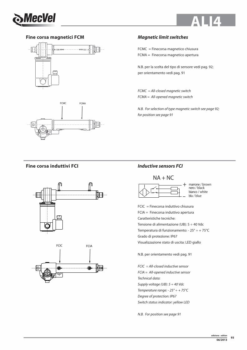
Fine corsa magnetici FCM
Fine corsa induttivi FCI
Magnetic limit switches
Inductive sensors FCI
FCMC = Finecorsa magnetico chiusura
FCMA = Finecorsa magnetico apertura
N.B. per la scelta del tipo di sensore vedi pag. 92;
per orientamento vedi pag. 91
FCMC = All-closed magnetic switch
FCMA = All-opened magnetic switch
N.B. For selection of type magnetic switch see page 92;
for position see page 91
FCIC = Finecorsa induttivo chiusura
FCIA = Finecorsa induttivo apertura
Caratteristiche tecniche:
Tensione di alimentazione (UB): 5 ÷ 40 Vdc
Temperatura di funzionamento: - 25° ÷ + 75°C
Grado di protezione: IP67
Visualizzazione stato di uscita: LED giallo
N.B. per orientamento vedi pag. 91
FCIC = All-closed inductive sensor
FCIA = All-opened inductive sensor
Technical data:
Supply voltage (UB): 5 ÷ 40 Vdc
Temperature range: - 25° ÷ + 75°C
Degree of protection: IP67
Switch status indicator: yellow LED
N.B. For position see page 91
NA + NCnero / blackmarrone / brown
bianco / whiteblu / blue
+
–
I
FCMC FCMA
FCIC FCIA
edizione - edition
94
ALI4
06/2013
Dispositivi Controllo Corsa
Elettrici / Elettronici
Stroke Control Devices
Electric / Electronic
Caratteristiche tecniche micro
Le caratteristiche dei microinterruttori di finecorsa montati sono le seguenti:• Alloggiamento: resina fenolica / melaminica termosaldata• Meccanismo: azione a scatto con molla in bronzo / berillio.
Un contatto in scambio NC/NO
Switches technical features
Limit Switches Features
• Housing: Phoenolic-melamine thermosetting• Mechanism: Snap-action coil spring mechanism with beryl-
Nota: la combinazione fine corsa + potenziometro dev’essere valutata con il nostro Ufficio Tecnico per corse eccedenti rispetto a quelle riportate sulle tabelle delle prestazioni
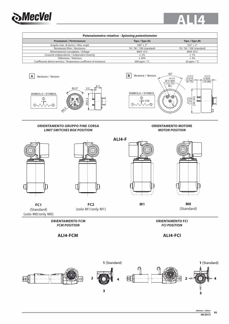
Alimentazione consigliata / Voltage MAX 10 V MAX 50 VLinearità indipendente / Indipendent linearity ± 2% ± 1%
Tolleranza / Tolerance ± 20% ± 3%Coefficente deriva termica / Temperature coefficient of resistance 600 ppm / °C 20 ppm / °C
FC1
(Standard)(solo M0/only M0)
FC2
(solo M1/only M1)M1 M0
(Standard)
ALI4-F
ALI4-FCIALI4-FCM
1 (Standard)
2
3
4
1 (Standard)
3
2 4
edizione - edition
96
ALI4
06/2013
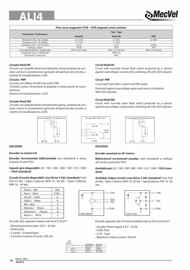
Circuito Reed NC
Circuito con ampolla Reed normalmente chiusa protetta da vari-store contro le sovratensioni generate all’apertura del circuito, e sistema di visualizzazione a LED.
Circuito PNP
Circuito con effetto di Hall con uscita PNP. Protetto contro l’inversione di polarità e contro picchi di sovra-tensione.Sistema di visualizzazione a LED.
Circuito Reed NO
Circuito con ampolla Reed normalmente aperta, protetta da vari-store contro le sovratensioni generate all’apertura del circuito, e sistema di visualizzazione a LED.
Circuit Redd NC
Circuit with normally closed Reed switch protected by a varistor against overvoltages caused when switching off, with LED indicator.
Circuit PNP
Circuit with Hall-effect switch and PNP outlet.
Protected against overvoltage spikes and reverse of polarity.With LED indicator.
Circuit Redd NO
Circuit with normally open Reed switch protected by a varistor against overvoltages caused when switching off, with LED indicator.
+ Vdc
0 Vdc
LINE DRIVER
OutOut
+ Vdc
0 Vdc
PUSH-PULL
Out
Rosso / Red ÷VdcNero / Black 0 VdcVer de / Green AGiallo / Yellow BBlu / Blue ZMarrone / Brown -AArancione / Orange -BBianco / White -Z
ENCODER
Encoder su motori CA
Encoder incrementale bidirezionale con (standard) e senza impulso di zero IP54.
POT01A = 1 k OhmPOT05A = 5 k OhmPOT10A = 10 k Ohm(standard version)
POT01B = 1 k OhmPOT05B = 5 k OhmPOT10B = 10 k Ohm(standard version)
Encoder:
(only on DC motor)E01 = NPN 2 channels 1 ppr
(only on AC motor)E05 = Push Pull 1024 pprE06 = Line Drive 1024 ppr (standard) E07 = Open Collector NPNE08 = Open Collector PNP
(only on actuator housing)E00 = Push Pull 2 channels 4 ppr E09 = Push Pull 1024 pprE10 = Line Drive 1024 pprE11 = Open Collector NPNE12 = Open Collector PNP
E13 = Encoder not considered above (according to customer request)
edizione - edition
98
ALI4
06/2013
VARIANTI MOTORE CA / AC MOTOR OPTIONS
Flangia tipo / Motorflange type: PAM56B14 / PAM63B14
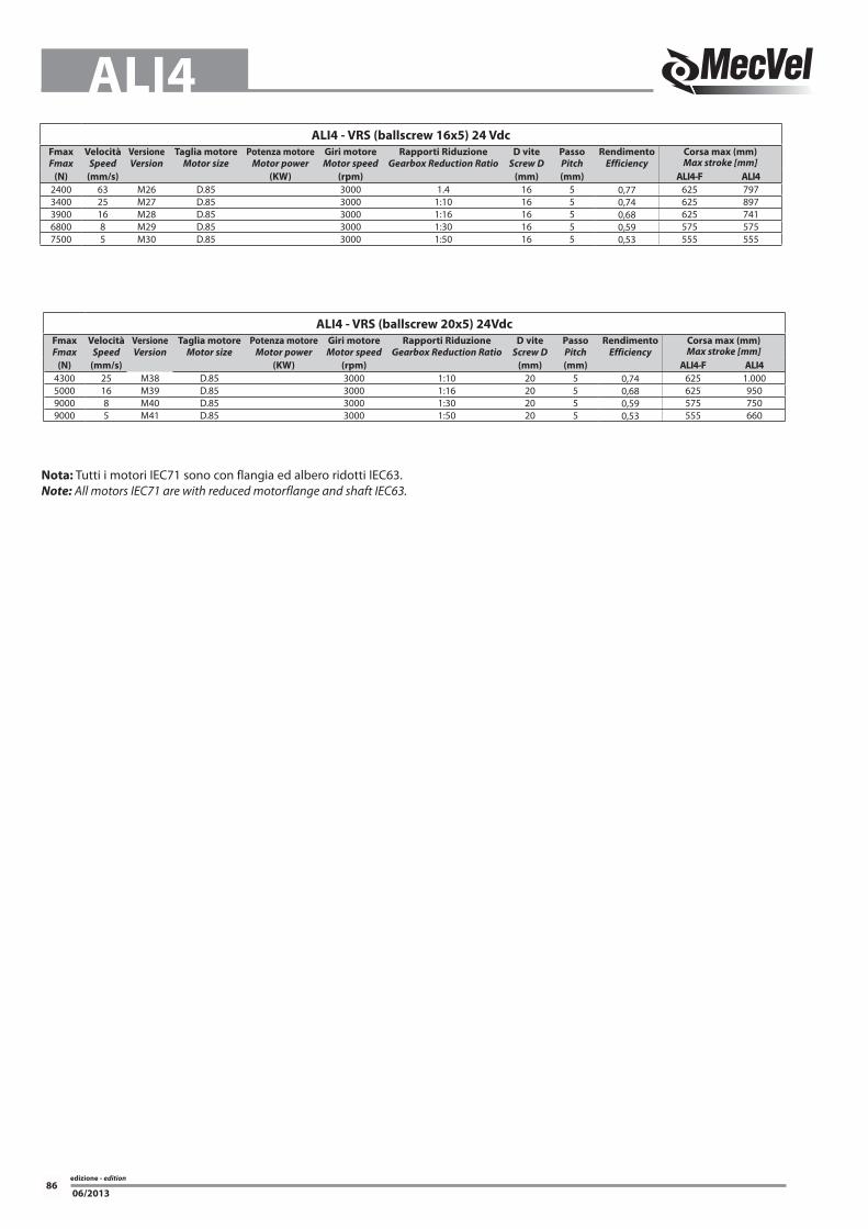
Nota: Tutti i motori IEC71 sono con flangia ed albero ridotti IEC63.
Note: All motors IEC71 are with reduced motorflange and shaft IEC63.
Tipo servizio / Service rate: S1 / S2 / S3
Classe isolamento / Insulation class: F = standard (non indicare)/ standard (leave blank) Specificare solo se diversa / Advise only if different than “F”
TP = tropicalizzato / tropicalization IN = avvolgimento per inverter / winding for inverters ALTRO / OTHER = indicare per esteso / advise SENZA / NONE = omettere / leave blank
Guida alla scelta della motorizzazione - Motor choice guideline
TIPO MOTORE / MOTOR TYPE
Versione / Version: CC = corrente continua / DC = direct current CA = corrente alternata / AC = alternate current PD = PAM a disegno / Special motorflange (provide drawing)
Tipo / Type: T = trifase / 3-phase(Solo per CA / only for AC) M = monofase / 1-phase AT = trifase autofrenante / 3-phase with brake AM = monofase autofrenante / 1-phase with brake ME = monofase con condensatore elettronico / 1-phase with starting capacitor AE = monofase autofr. con condensatore elettronico / 1-phase with brake and starting capacitor
Grandezza / Size: CC / DC: D.85 CA / AC: IEC 56/63/71
N°Poli / Pole: CA / AC: 2 / 4 / 6N°Giri / RPM’s: CC / DC: 3000 RPM 24 V (Standard) 12 V
* Nota: Tutti i motori IEC71 sono con flangia ed albero ridotti IEC63. Note: All motors IEC71 are with reduced motorflange and shaft IEC63.
edizione - edition
99
ALI4
06/2013
Freno / Brake: FECC = freno elettromagnetico negativo in CC / DC brake negative action (standard)
Tensione di alimentazione 230V± 10% 50/60Hz dal lato A.C. dell’alimentatore freno. Il freno viene alimentato direttamente dall’alimentazione del motore. (standard) Sono disponibili a richiesta motori con freni con alimentazione separata e con tensioni nel range (24-205 Vdc) In questo caso il freno necessita di una alimentazione separata da quella del motore. In questo caso la sigla diventa FECC-AS-24Vdc
Power Supply 230V±10% 50/60Hz AC side inside the brake. The brake is powered directly from the power supply of the motor (standard) Motors with separated brake power supply and tensions in the range (24-205 Vdc) can be available on request. In this case the brake needs a separated power supply from the motor and its code becomes FECC-AS-24 Vdc
FECA= freno elettromagnetico in CA / AC brake Tensione di alimentazione 230/400V± 10% 50/60Hz. Il freno viene alimentato direttamente dall’alimentazione del motore. Sono disponibili a richiesta motori con freni con alimentazione separata e con tensioni nel range (24-690 Vac) 50/60 HZ In questo caso il freno necessita di una alimentazione separata da quella del motore. In questo caso la sigla diventa FECA-AS-230 Vac 50 HZ
Power Supply 230/400V±10% 50/60Hz. The brake is powered directly from the power supply of the motor. Motors with separated brake power supply and tensions in the range (24-690 Vac - 50/60 Hz) can be available on request. In this case the brake needs a separated power supply from the motor and its code becomes FECA-AS-230 Vac 50 HZ
Alimentazione separata del freno / Separate brake power supply: si ottiene tramite una morsettiera ausiliaria, con fissati i morsetti delle bobine freno, posizionata all’interno del coprimorsettiera motore. achieved by means of an auxiliary terminal board, with fixed brake coil terminals, located inside the motor terminal box.
Nb. Per tutti i motori predisposti inverter il freno deve avere senpre l’alimentazione separata Nb. On all motors prepared for frequency converter the brake must always have a separate power supply
SENZA = omettere / NO BRAKE = leave blank
Opzioni / Options: LS = leva sblocco / hand release lever (non indicare / leave blank) Nota: = non disponibile per motori IEC 50 IEC 56 / NOTE: not available for motor IEC 50 IEC 56
AB = albero bisporgente / 2’shaft IN = avvolgimento per inverter / winding for inverters ALTRO / OTHER = indicare per esteso / advise SENZA / NONE = omettere / leave blank
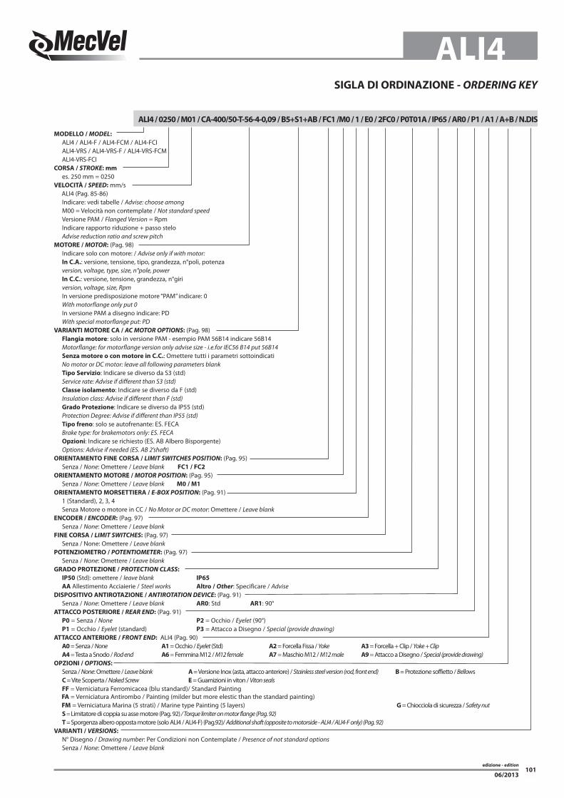
es. 250 mm = 0250VELOCITÀ / SPEED: mm/s ALI4 (Pag. 85-86) Indicare: vedi tabelle / Advise: choose among M00 = Velocità non contemplate / Not standard speed Versione PAM / Flanged Version = Rpm Indicare rapporto riduzione + passo stelo Advise reduction ratio and screw pitchMOTORE / MOTOR: (Pag. 98) Indicare solo con motore: / Advise only if with motor: In C.A.: versione, tensione, tipo, grandezza, n°poli, potenza version, voltage, type, size, n°pole, power In C.C.: versione, tensione, grandezza, n°giri version, voltage, size, Rpm In versione predisposizione motore “PAM” indicare: 0 With motorflange only put 0 In versione PAM a disegno indicare: PD With special motorflange put: PDVARIANTI MOTORE CA / AC MOTOR OPTIONS: (Pag. 98) Flangia motore: solo in versione PAM - esempio PAM 56B14 indicare 56B14 Motorflange: for motorflange version only advise size - i.e.for IEC56 B14 put 56B14 Senza motore o con motore in C.C.: Omettere tutti i parametri sottoindicati No motor or DC motor: leave all following parameters blank Tipo Servizio: Indicare se diverso da S3 (std) Service rate: Advise if different than S3 (std) Classe isolamento: Indicare se diverso da F (std) Insulation class: Advise if different than F (std) Grado Protezione: Indicare se diverso da IP55 (std) Protection Degree: Advise if different than IP55 (std) Tipo freno: solo se autofrenante: ES. FECA Brake type: for brakemotors only: ES. FECA Opzioni: Indicare se richiesto (ES. AB Albero Bisporgente) Options: Advise if needed (ES. AB 2’shaft)ORIENTAMENTO FINE CORSA / LIMIT SWITCHES POSITION: (Pag. 95) Senza / None: Omettere / Leave blank FC1 / FC2
ORIENTAMENTO MOTORE / MOTOR POSITION: (Pag. 95) Senza / None: Omettere / Leave blank M0 / M1
ORIENTAMENTO MORSETTIERA / E-BOX POSITION: (Pag. 91) 1 (Standard), 2, 3, 4 Senza Motore o motore in CC / No Motor or DC motor: Omettere / Leave blankENCODER / ENCODER: (Pag. 97) Senza / None: Omettere / Leave blankFINE CORSA / LIMIT SWITCHES: (Pag. 97) Senza / None: Omettere / Leave blankPOTENZIOMETRO / POTENTIOMETER: (Pag. 97) Senza / None: Omettere / Leave blankGRADO PROTEZIONE / PROTECTION CLASS:
IP50 (Std): omettere / leave blank IP65
AA Allestimento Acciaierie / Steel works Altro / Other: Specificare / AdviseDISPOSITIVO ANTIROTAZIONE / ANTIROTATION DEVICE: (Pag. 91) Senza / None: Omettere / Leave blank AR0: Std AR1: 90°ATTACCO POSTERIORE / REAR END: (Pag. 91) P0 = Senza / None P2 = Occhio / Eyelet (90°) P1 = Occhio / Eyelet (standard) P3 = Attacco a Disegno / Special (provide drawing)ATTACCO ANTERIORE / FRONT END: ALI4 (Pag. 90) A0 = Senza / None A1 = Occhio / Eyelet (Std) A2 = Forcella Fissa / Yoke A3 = Forcella + Clip / Yoke + Clip A4 = Testa a Snodo / Rod end A6 = Femmina M12 / M12 female A7 = Maschio M12 / M12 male A9 = Attacco a Disegno / Special (provide drawing)OPZIONI / OPTIONS:
Senza / None: Omettere / Leave blank A = Versione Inox (asta, attacco anteriore) / Stainless steel version (rod, front end) B = Protezione soffietto / Bellows C = Vite Scoperta / Naked Screw E = Guarnizioni in viton / Viton seals FF = Verniciatura Ferromicacea (blu standard)/ Standard Painting FA = Verniciatura Antirombo / Painting (milder but more elestic than the standard painting) FM = Verniciatura Marina (5 strati) / Marine type Painting (5 layers) G = Chiocciola di sicurezza / Safety nut S = Limitatore di coppia su asse motore (Pag. 92) / Torque limiter on motor flange (Pag. 92) T = Sporgenza albero opposta motore (solo ALI4 / ALI4-F) (Pag.92)/ Additional shaft (opposite to motorside - ALI4 / ALI4-F only) (Pag. 92)VARIANTI / VERSIONS:
N° Disegno / Drawing number: Per Condizioni non Contemplate / Presence of not standard options Senza / None: Omettere / Leave blank