84
| Date post: | 10-Dec-2018 |
| Category: |
Documents |
| Upload: | vuongquynh |
| View: | 216 times |
| Download: | 0 times |

®
Aut. S.M.A. n° 12-114
2SOMMARIO
RULLI D'ACCIAIO
pag. 4 Descrizione dei rulli d'acciaio 7 Capacità di carico dei rulli d'acciaio12 Scelta dei rulli d'acciaio24 Esempio di calcolo29 Lunghezze normali30 Finitura dei rulli e temperatura d’esercizio 32 Designazione codice dei rulli d'acciaio
RULLI D'ACCIAIO GRAFFATI
pag. 34 Esecuzione dei rulli d'acciaio graffati36 Rulli d'acciaio graffati Serie 13.037 Rulli d'acciaio graffati Serie 13.1.038 Rulli d'acciaio graffati Serie 13.2.039 Rulli d'acciaio graffati Serie 13.3.040 Rulli d'acciaio graffati Serie 17.1.0
RULLI D'ACCIAIO MONOBLOCCO
pag. 42 Esecuzione dei rulli d'acciaio monoblocco44 Rulli d'acciaio monoblocco Serie 14.045 Rulli d'acciaio monoblocco Serie 15.046 Rulli d'acciaio monoblocco Serie 15.1.047 Rulli d'acciaio monoblocco Serie 20.048 Rulli d'acciaio monoblocco Serie 20.1.049 Rulli d'acciaio monoblocco Serie 20.2.050 Rulli d'acciaio monoblocco Serie 25.051 Rulli d'acciaio monoblocco Serie 25.1.052 Rulli d'acciaio monoblocco Serie 25.2.053 Rulli d'acciaio monoblocco Serie 30.054 Rulli d'acciaio monoblocco Serie 30.1.055 Rulli d'acciaio monoblocco Serie 30.2.056 Rulli d'acciaio monoblocco Serie 40.057 Rulli d'acciaio monoblocco Serie 40.1.058 Rulli d'acciaio monoblocco Serie 40.2.0
RULLI D'ACCIAIO SPECIALI
pag. 60 Esecuzione dei gruppi a ghirlanda61 Gruppi a ghirlanda con tre rulli Serie 3.162 Gruppi a ghirlanda con cinque rulli Serie 3.263 Gruppi a ghirlanda con due rulli Serie 3.364 Gruppi a sbalzo con due rulli Serie 3.465 Rulli guida nastro Serie 6
RULLI DI PVC E PVC-ACCIAIO
pag. 68 Descrizione dei rulli di PVC e PVC-ACCIAIO 70 Capacità di carico dei rulli di PVC e PVC-ACCIAIO 72 Designazione codice dei rulli di PVC e PVC-ACCIAIO 74 Esecuzione dei rulli di PVC e PVC-ACCIAIO76 Rulli di PVC Serie 21.077 Rulli di PVC-ACCIAIO Serie 21.1.0
3®
INDEX
STEEL ROLLERS
page 4 Description of steel rollers7 Steel rollers’ load capacity12 Selecting steel rollers24 Sample calculation29 Normal lengths30 Rollers’ finishing and operating temperature32 Code designation of the steel rollers
CLAMPED STEEL ROLLERS
page 34 Construction of clamped steel rollers36 Clamped steel rollers Series 13.037 Clamped steel rollers Series 13.1.038 Clamped steel rollers Series 13.2.039 Clamped steel rollers Series 13.3.040 Clamped steel rollers Series 17.1.0
ENBLOC STEEL ROLLERS
page 42 Construction of enbloc steel rollers44 Enbloc steel rollers Series 14.045 Enbloc steel rollers Series 15.046 Enbloc steel rollers Series 15.1.047 Enbloc steel rollers Series 20.048 Enbloc steel rollers Series 20.1.049 Enbloc steel rollers Series 20.2.050 Enbloc steel rollers Series 25.051 Enbloc steel rollers Series 25.1.052 Enbloc steel rollers Series 25.2.053 Enbloc steel rollers Series 30.054 Enbloc steel rollers Series 30.1.055 Enbloc steel rollers Series 30.2.056 Enbloc steel rollers Series 40.0.57 Enbloc steel rollers Series 40.1.058 Enbloc steel rollers Series 40.2.0
SPECIAL STEEL ROLLERS
page 60 Construction of garland groups61 3-Roller garland groups Series 3.162 5-Roller garland groups Series 3.263 2-Roller garland groups Series 3.364 2-Roller cantilever assemblies Series 3.465 Belt-guide rollers Series 6
PVC AND PVC-STEEL ROLLERS
page 68 Description of PVC and PVC-STEEL rollers70 PVC and PVC-STEEL rollers’ load capacity72 Code designation of PVC and PVC-STEEL rollers74 Construction of PVC and PVC-STEEL rollers76 PVC rollers Series 21.077 PVC-STEEL rollers Series 21.1.0
4
DESCRIZIONE DEI RULLI D’ACCIAIODESCRIPTION OF STEEL ROLLERS
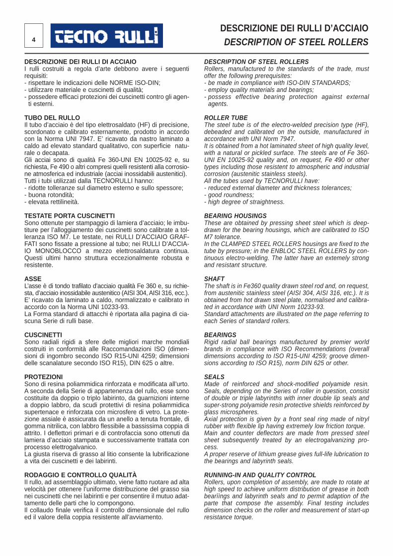
DESCRIZIONE DEI RULLI DI ACCIAIOI rulli costruiti a regola d’arte debbono avere i seguentirequisiti:- rispettare le indicazioni delle NORME ISO-DIN;- utilizzare materiale e cuscinetti di qualità;- possedere efficaci protezioni dei cuscinetti contro gli agen-ti esterni.
TUBO DEL RULLOIl tubo d’acciaio è del tipo elettrosaldato (HF) di precisione,scordonato e calibrato esternamente, prodotto in accordocon la Norma UNI 7947. E’ ricavato da nastro laminato acaldo ad elevato standard qualitativo, con superficie natu-rale o decapata.Gli acciai sono di qualità Fe 360-UNI EN 10025-92 e, surichiesta, Fe 490 o altri compresi quelli resistenti alla corrosio-ne atmosferica ed industriale (acciai inossidabili austenitici).Tutti i tubi utilizzati dalla TECNORULLI hanno:- ridotte tolleranze sul diametro esterno e sullo spessore;- buona rotondità;- elevata rettilineità.
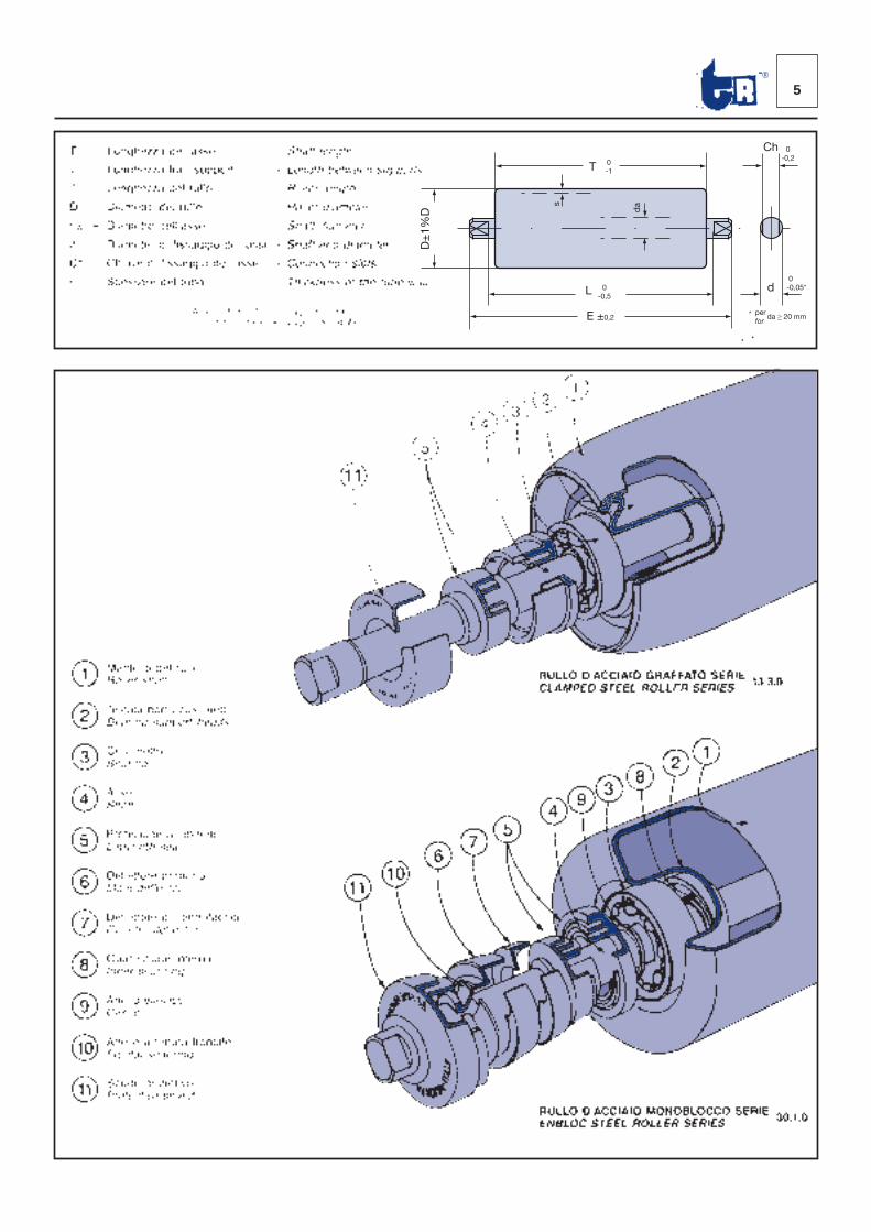
TESTATE PORTA CUSCINETTISono ottenute per stampaggio di lamiera d’acciaio; le imbu-titure per l’alloggiamento dei cuscinetti sono calibrate a tol-leranza ISO M7. Le testate, nei RULLI D’ACCIAIO GRAF-FATI sono fissate a pressione al tubo; nei RULLI D’ACCIA-IO MONOBLOCCO a mezzo elettrosaldatura continua.Questi ultimi hanno struttura eccezionalmente robusta eresistente.
ASSEL’asse è di tondo trafilato d’acciaio qualità Fe 360 e, su richie-sta, d’acciaio inossidabile austenitico (AISI 304, AISI 316, ecc.).E’ ricavato da laminato a caldo, normalizzato e calibrato inaccordo con la Norma UNI 10233-93.La Forma standard di attacchi è riportata alla pagina di cia-scuna Serie di rulli base.
CUSCINETTISono radiali rigidi a sfere delle migliori marche mondialicostruiti in conformità alle Raccomandazioni ISO (dimen -sioni di ingombro secondo ISO R15-UNI 4259; dimensio nidelle scanalature secondo ISO R15), DIN 625 o altre.
PROTEZIONISono di resina poliammidica rinforzata e modificata all’urto.A seconda della Serie di appartenenza del rullo, esse sonocostituite da doppio o triplo labirinto, da guarnizioni internea doppio labbro, da scudi protettivi di resina po liammidicasupertenace e rinforzata con microsfere di vetro. La prote-zione assiale è assicurata da un anello a tenuta frontale, digomma nitrilica, con labbro flessibile a bas sissima coppia diattrito. I deflettori primari e di controfaccia sono ottenuti dalamiera d’acciaio stampata e successivamente trattata conprocesso elettrogalvanico. La giusta riserva di grasso al litio consente la lubrifica zionea vita dei cuscinetti e dei labirinti.
RODAGGIO E CONTROLLO QUALITÀII rullo, ad assemblaggio ultimato, viene fatto ruotare ad altavelocità per ottenere l’uniforme distribuzione del gras so sianei cuscinetti che nei labirinti e per consentire il mutuo adat-tamento delle parti che lo compongono. Il collaudo finale verifica il controllo dimensionale del rul loed il valore della coppia resistente all’avviamento.
DESCRIPTION OF STEEL ROLLERSRollers, manufactured to the standards of the trade, mustoffer the following prerequisites:- be made in compliance with ISO-DIN STANDARDS;- employ quality materials and bearings;- possess effective bearing protection against externalagents.
ROLLER TUBEThe steel tube is of the electro-welded precision type (HF),debeaded and calibrated on the outside, manufactured inaccordance with UNI Norm 7947. It is obtained from a hot laminated sheet of high quality level,with a natural or pickled surface. The steels are of Fe 360-UNI EN 10025-92 quality and, on request, Fe 490 or othertypes including those resistent to atmospheric and industrialcorrosion (austenitic stainless steels).All the tubes used by TECNORULLI have:- reduced external diameter and thickness tolerances;- good roundness;- high degree of straightness.
BEARING HOUSINGSThese are obtained by pressing sheet steel which is deep-drawn for the bearing housings, which are calibrated to ISOM7 tolerance.In the CLAMPED STEEL ROLLERS housings are fixed to thetube by pressure; in the ENBLOC STEEL ROLLERS by con-tinuous electro-welding. The latter have an extemely strongand resistant structure.
SHAFTThe shaft is in Fe360 quality drawn steel rod and, on request,from austenitic stainless steel (AISI 304, AISI 316, etc.). It isobtained from hot drawn steel plate, normalised and calibra-ted in accordance with UNI Norm 10233-93.Standard attachments are illustrated on the page referring toeach Series of standard rollers.
BEARINGSRigid radial ball bearings manufactured by premier worldbrands in compliance with ISO Recommendations (overalldimensions according to ISO R15-UNI 4259; groove dimen-sions according to ISO R15), norm DIN 625 or other.
SEALSMade of reinforced and shock-modified polyamide resin.Seals, depending on the Series of roller in question, consistof double or triple labyrinths with inner double lip seals andsuper-strong polyamide resin protective shields reinforced byglass microspheres.Axial protection is given by a front seal ring made of nitrylrubber with flexible lip having extremely low friction torque. Main and counter deflectors are made from pressed steelsheet subsequently treated by an electrogalvanizing pro-cess.A proper reserve of lithium grease gives full-life lubrication tothe bearings and labyrinth seals.
RUNNING-IN AND QUALITY CONTROLRollers, upon completion of assembly, are made to rotate athigh speed to achieve uniform distribution of grease in bothbearììngs and labyrinth seals and to permit adaption of theparte that compose the assembly. Final testing includesdimension checks on the roller and measurement of start-upresistance torque.
5®
T
Ch
d
0 -1
D±
1%D
s
da
L 0 -0,5
E ±0,2
0 -0,2
0 -0,05*
* per for
da ≥ 20 mm
6
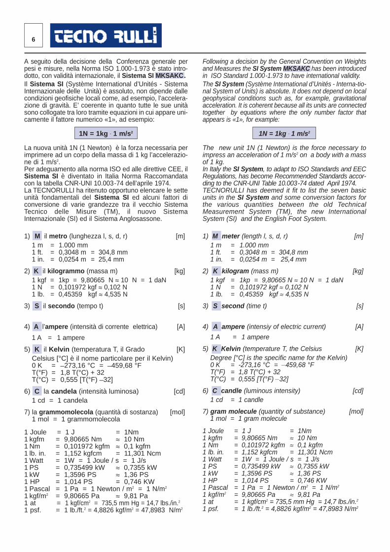
A seguito della decisione della Conferenza generale perpesi e misure, nella Norma ISO 1.000-1.973 è stato intro-dotto, con validità internazionale, il Sistema SI MKSAKC.Il Sistema SI (Système International d’Unités - SistemaInternazionale delle Unità) è assoluto, non dipende dallecondizioni geofisiche locali come, ad esempio, l’accelera-zione di gravità. E’ coerente in quanto tutte le sue unitàsono collogate tra loro tramite equazioni in cui appare uni-camente il fattore numerico «1», ad esempio:
1N = 1kg · 1 m/s2
La nuova unità 1N (1 Newton) è la forza necessaria perimprimere ad un corpo della massa di 1 kg l’accelerazio-ne di 1 m/s2.Per adeguamento alla norma ISO ed alle direttive CEE, ilSistema SI è diventato in Italia Norma Raccomandatacon la tabella CNR-UNI 10.003-74 dell’aprile 1974.La TECNORULLI ha ritenuto opportuno elencare le setteunità fondamentali del Sistema SI ed alcuni fattori diconversione di varie grandezze tra il vecchio SistemaTecnico delle Misure (TM), il nuovo SistemaInternazionale (SI) ed il Sistema Anglosassone.
1) M il metro (lunghezza l, s, d, r) [m]1 m = 1.000 mm1 ft. = 0,3048 m = 304,8 mm1 in. = 0,0254 m = 25,4 mm
2) K il kilogrammo (massa m) [kg]1 kgf = 1kp = 9,80665 N ≈ 10 N = 1 daN1 N = 0,101972 kgf ≈ 0,102 N1 lb. = 0,45359 kgf ≈ 4,535 N
3) S il secondo (tempo t) [s]
4) A l’ampere (intensità di corrente elettrica) [A]
1 A = 1 ampere
5) K il Kelvin (temperatura T, il Grado [K]Celsius [°C] è il nome particolare per il Kelvin)0 K = _273,16 °C = _459,68 °FT(°F) = 1,8 T(°C) + 32T(°C) = 0,555 [T(°F) _32]
6) C la candela (intensità luminosa) [cd]1 cd = 1 candela
7) la grammomolecola (quantità di sostanza) [mol]1 mol = 1 grammomolecola
1 Joule = 1 J = 1Nm 1 kgfm = 9,80665 Nm ≈ 10 Nm1 Nm = 0,101972 kgfm ≈ 0,1 kgfm1 lb. in. = 1,152 kgfcm = 11,301 Ncm1Watt = 1W = 1 Joule / s = 1 J/s1 PS = 0,735499 kW ≈ 0,7355 kW1 kW = 1,3596 PS ≈ 1,36 PS1 HP = 1,014 PS = 0,746 KW1 Pascal = 1 Pa = 1 Newton / m2 = 1 N/m2
1 kgf/m2 = 9,80665 Pa ≈ 9,81 Pa1 at = 1 kgf/cm2 = 735,5 mm Hg = 14,7 lbs./in.21 psf. = 1 lb./ft.2 = 4,8826 kgf/m2 = 47,8983 N/m2
Following a decision by the General Convention on Weightsand Measures the SI System MKSAKC has been introducedin ISO Standard 1.000-1.973 to have international validity.The SI System (Système International d’Unités - Interna-tio-nal System of Units) is absolute. It does not depend on localgeophysical conditions such as, for example, gravitationalacceleration. It is coherent because all its units are connectedtogether by equations where the only number factor thatappears is «1», for example:
1N = 1kg · 1 m/s2
The new unit 1N (1 Newton) is the force necessary toimpress an acceleration of 1 m/s2 on a body with a massof 1 kg.In Italy the SI System, to adapt to ISO Standards and EECRegulations, has become Recommended Standards accor-ding to the CNR-UNI Table 10.003-74 dated April 1974. TECNORULLI has deemed it fit to list the seven basicunits in the SI System and some conversion factors forthe various quantities between the old TechnicalMeasurement System (TM), the new InternationalSystem (SI) and the English Foot System.
1) M meter (length l, s, d, r) [m]1 m = 1.000 mm1 ft. = 0,3048 m = 304,8 mm1 in. = 0,0254 m = 25,4 mm
2) K kilogram (mass m) [kg]1 kgf = 1kp = 9,80665 N ≈ 10 N = 1 daN1 N = 0,101972 kgf ≈ 0,102 N1 lb. = 0,45359 kgf ≈ 4,535 N
3) S second (time t) [s]
4) A ampere (intensiy of electric current) [A]
1 A = 1 ampere
5) K Kelvin (temperature T, the Celsius [K]Degree [°C] is the specific name for the Kelvin)0 K = -273,16 °C = _459,68 °FT(°F) = 1,8 T(°C) + 32T(°C) = 0,555 [T(°F) _32]
6) C candle (luminous intensity) [cd] 1 cd = 1 candle
7) gram molecule (quantity of substance) [mol]1 mol = 1 gram molecule
1 Joule = 1 J = 1Nm 1 kgfm = 9,80665 Nm ≈ 10 Nm1 Nm = 0,101972 kgfm ≈ 0,1 kgfm1 lb. in. = 1,152 kgfcm = 11,301 Ncm1 Watt = 1W = 1 Joule / s = 1 J/s1 PS = 0,735499 kW ≈ 0,7355 kW1 kW = 1,3596 PS ≈ 1,36 PS1 HP = 1,014 PS = 0,746 KW1 Pascal = 1 Pa = 1 Newton / m2 = 1 N/m2
1 kgf/m2 = 9,80665 Pa ≈ 9,81 Pa1 at = 1 kgf/cm2 = 735,5 mm Hg = 14,7 lbs./in.21 psf. = 1 lb./ft.2 = 4,8826 kgf/m2 = 47,8983 N/m2
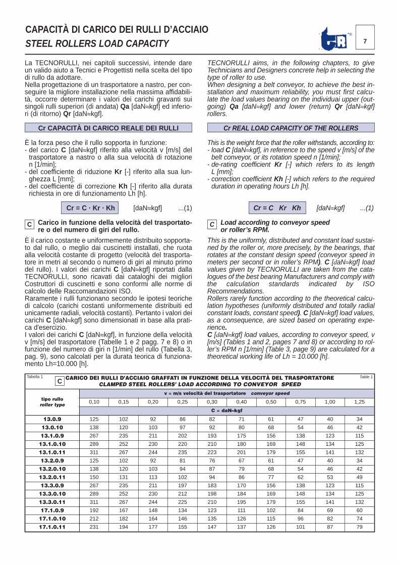
La TECNORULLI, nei capitoli successivi, intende dareun valido aiuto a Tecnici e Progettisti nella scelta del tipodi rullo da adottare.Nella progettazione di un trasportatore a nastro, per con-seguire la migliore installazione nella massima affidabili-tà, occorre determinare i valori dei carichi gravanti suisingoli rulli superiori (di andata) Qa [daN≈kgf] ed inferio-ri (di ritorno) Qr [daN≈kgf].
Cr CAPACITÀ DI CARICO REALE DEI RULLI
È la forza peso che il rullo sopporta in funzione:- del carico C [daN≈kgf] riferito alla velocità v [m/s] deltrasportatore a nastro o alla sua velocità di rotazionen [1/min];- del coefficiente di riduzione Kr [-] riferito alla sua lun-ghezza L [mm];- del coefficiente di correzione Kh [-] riferito alla duratarichiesta in ore di funzionamento Lh [h].
Cr = C · Kr · Kh [daN≈kgf] ...(1)
Carico in funzione della velocità del trasportato-re o del numero di giri del rullo.
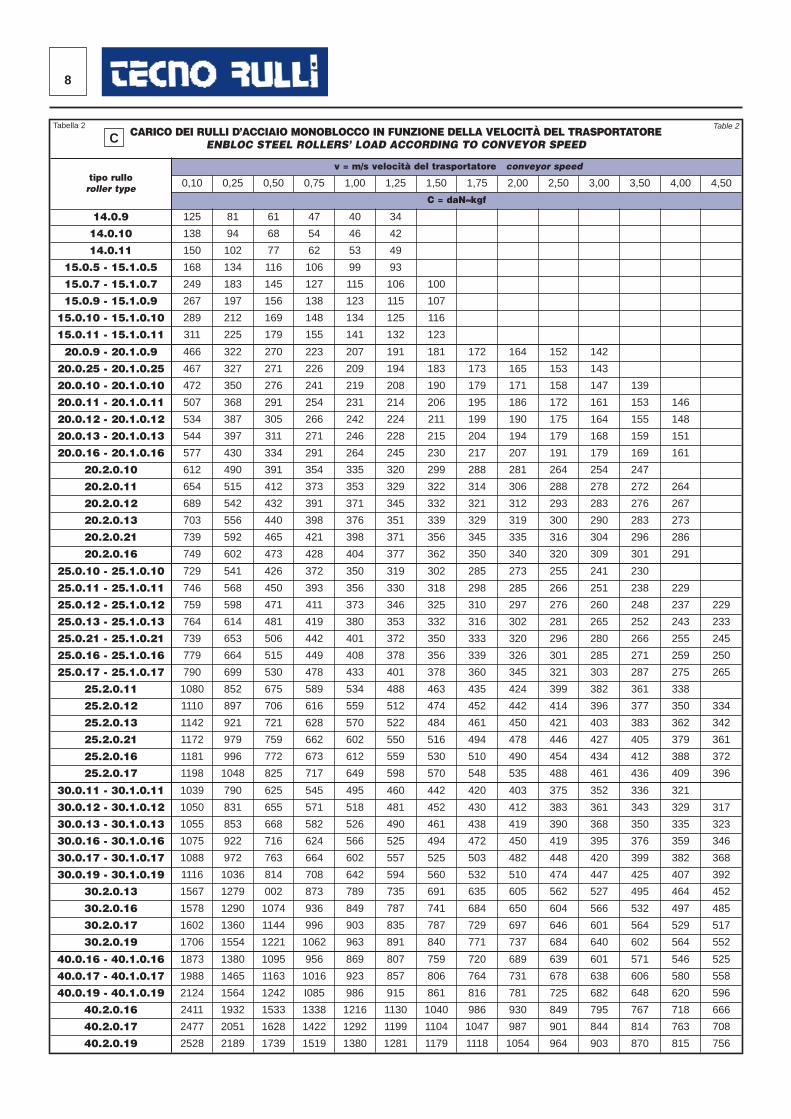
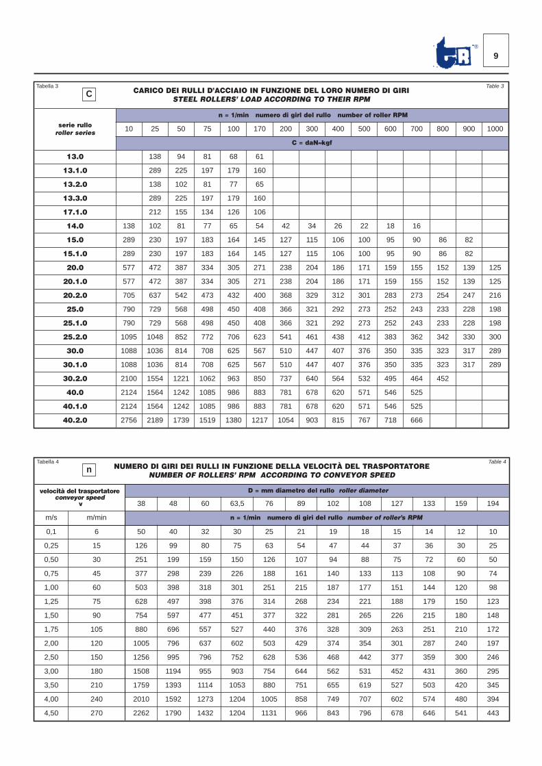
È il carico costante e uniformemente distribuito sopporta-to dal rullo, o meglio dai cuscinetti installati, che ruotaalla velocità costante di progetto (velocità del trasporta-tore in metri al secondo o numero di giri al minuto primodel rullo). I valori dei carichi C [daN≈kgf] riportati dallaTECNORULLI, sono ricavati dai cataloghi dei miglioriCostruttori di cuscinetti e sono conformi alle norme dicalcolo delle Raccomandazioni ISO.Raramente i rulli funzionano secondo le ipotesi teorichedi calcolo (carichi costanti uniformemente distribuiti edunicamente radiali, velocità costanti). Pertanto i valori deicarichi C [daN≈kgf] sono dimensionati in base alla prati-ca d'esercizio.I valori dei carichi C [daN≈kgf], in funzione della velocitàv [m/s] del trasportatore (Tabelle 1 e 2 pagg. 7 e 8) o infunzione del numero di giri n [1/min] del rullo (Tabella 3,pag. 9), sono calcolati per la durata teorica di funziona-mento Lh=10.000 [h].
7®
CAPACITÀ DI CARICO DEI RULLI D’ACCIAIOSTEEL ROLLERS LOAD CAPACITY
CARICO DEI RULLI D’ACCIAIO GRAFFATI IN FUNZIONE DELLA VELOCITÀ DEL TRASPORTATORECLAMPED STEEL ROLLERS’ LOAD ACCORDING TO CONVEYOR SPEED
tipo rulloroller type
v = m/s velocità del trasportatore conveyor speed
0,10 0,15 0,20 0,25 0,30 0,40 0,50 0,75 1,00 1,25
C = daN≈kgf
13.0.9 125 102 92 86 82 71 61 47 40 34
13.0.10 138 120 103 97 92 80 68 54 46 42
13.1.0.9 267 235 211 202 193 175 156 138 123 115
13.1.0.10 289 252 230 220 210 180 169 148 134 125
13.1.0.11 311 267 244 235 223 201 179 155 141 132
13.2.0.9 125 102 92 81 76 67 61 47 40 34
13.2.0.10 138 120 103 94 87 79 68 54 46 42
13.2.0.11 150 131 113 102 94 86 77 62 53 49
13.3.0.9 267 235 211 197 183 170 156 138 123 115
13.3.0.10 289 252 230 212 198 184 169 148 134 125
13.3.0.11 311 267 244 225 210 195 179 155 141 132
17.1.0.9 192 167 148 134 123 111 102 84 69 60
17.1.0.10 212 182 164 146 135 126 115 96 82 74
17.1.0.11 231 194 177 155 147 137 126 101 87 79
Tabella 1 Table 1
TECNORULLI aims, in the following chapters, to giveTechnicians and Designers concrete help in selecting thetype of roller to use.When designing a belt conveyor, to achieve the best in-stallation and maximum reliability, you must first calcu-late the load values bearing on the individuai upper (out-going) Qa [daN≈kgf] and lower (return) Qr [daN≈kgf]rollers.
Cr REAL LOAD CAPACITY OF THE ROLLERS
This is the weight force that the roller withstands, according to:- load C [daN≈kgf], in reference to the speed v [m/s] of thebelt conveyor, or its rotation speed n [1/min];- de-rating coefficient Kr [-] which refers to its lengthL [mm];- correction coefficient Kh [-] which refers to the requiredduration in operating hours Lh [h].
Cr = C · Kr · Kh [daN≈kgf] ...(1)
Load according to conveyor speedor roller’s RPM.
This is the uniformly, distributed and constant load sustai-ned by the roller or, more precisely, by the bearings, thatrotates at the constant design speed (conveyor speed inmeters per second or in roller’s RPM). C [daN≈kgf] loadvalues given by TECNORULLI are taken from the cata-logues of the best bearing Manufacturers and comply withthe calculation standards indicated by ISORecommendations.Rollers rarely function according to the theoretical calcu-lation hypotheses (uniformly distributed and totally radialconstant loads, constant speed). C [daN≈kgf] load values,as a consequence, are sized based on operating expe-rience.C [daN≈kgf] load values, according to conveyor speed, v[m/s] (Tables 1 and 2, pages 7 and 8) or according to rol-ler’s RPM n [1/min] (Table 3, page 9) are calculated for atheoretical working life of Lh = 10.000 [h].
C
C C
8
CARICO DEI RULLI D’ACCIAIO MONOBLOCCO IN FUNZIONE DELLA VELOCITÀ DEL TRASPORTATOREENBLOC STEEL ROLLERS’ LOAD ACCORDING TO CONVEYOR SPEED
tipo rulloroller type
v = m/s velocità del trasportatore conveyor speed
0,10 0,25 0,50 0,75 1,00 1,25 1,50 1,75 2,00 2,50 3,00 3,50 4,00 4,50
C = daN≈kgf
14.0.9 125 81 61 47 40 34
14.0.10 138 94 68 54 46 42
14.0.11 150 102 77 62 53 49
15.0.5 - 15.1.0.5 1 68 134 116 106 99 93
15.0.7 - 15.1.0.7 249 183 145 127 115 106 100
15.0.9 - 15.1.0.9 267 197 156 138 123 115 107
15.0.10 - 15.1.0.10 289 212 169 148 134 125 116
15.0.11 - 15.1.0.11 311 225 179 155 141 132 123
20.0.9 - 20.1.0.9 466 322 270 223 207 191 181 172 164 152 142
20.0.25 - 20.1.0.25 467 327 271 226 209 194 183 173 165 153 143
20.0.10 - 20.1.0.10 472 350 276 241 219 208 190 179 171 158 147 139
20.0.11 - 20.1.0.11 507 368 291 254 231 214 206 195 186 172 161 153 146
20.0.12 - 20.1.0.12 534 387 305 266 242 224 211 199 190 175 164 155 148
20.0.13 - 20.1.0.13 544 397 311 271 246 228 215 204 194 179 168 159 151
20.0.16 - 20.1.0.16 577 430 334 291 264 245 230 217 207 191 179 169 161
20.2.0.10 612 490 391 354 335 320 299 288 281 264 254 247
20.2.0.11 654 515 412 373 353 329 322 314 306 288 278 272 264
20.2.0.12 689 542 432 391 371 345 332 321 312 293 283 276 267
20.2.0.13 703 556 440 398 376 351 339 329 319 300 290 283 273
20.2.0.21 739 592 465 421 398 371 356 345 335 316 304 296 286
20.2.0.16 749 602 473 428 404 377 362 350 340 320 309 301 291
25.0.10 - 25.1.0.10 729 541 426 372 350 319 302 285 273 255 241 230
25.0.11 - 25.1.0.11 746 568 450 393 356 330 318 298 285 266 251 238 229
25.0.12 - 25.1.0.12 759 598 471 411 373 346 325 310 297 276 260 248 237 229
25.0.13 - 25.1.0.13 764 614 481 419 380 353 332 316 302 281 265 252 243 233
25.0.21 - 25.1.0.21 739 653 506 442 401 372 350 333 320 296 280 266 255 245
25.0.16 - 25.1.0.16 779 664 515 449 408 378 356 339 326 301 285 271 259 250
25.0.17 - 25.1.0.17 790 699 530 478 433 401 378 360 345 321 303 287 275 265
25.2.0.11 1080 852 675 589 534 488 463 435 424 399 382 361 338
25.2.0.12 1110 897 706 616 559 512 474 452 442 414 396 377 350 334
25.2.0.13 1142 921 721 628 570 522 484 461 450 421 403 383 362 342
25.2.0.21 1172 979 759 662 602 550 516 494 478 446 427 405 379 361
25.2.0.16 1181 996 772 673 612 559 530 510 490 454 434 412 388 372
25.2.0.17 1198 1048 825 717 649 598 570 548 535 488 461 436 409 396
30.0.11 - 30.1.0.11 1039 790 625 545 495 460 442 420 403 375 352 336 321
30.0.12 - 30.1.0.12 1050 831 655 571 518 481 452 430 412 383 361 343 329 317
30.0.13 - 30.1.0.13 1055 853 668 582 526 490 461 438 419 390 368 350 335 323
30.0.16 - 30.1.0.16 1075 922 716 624 566 525 494 472 450 419 395 376 359 346
30.0.17 - 30.1.0.17 1088 972 763 664 602 557 525 503 482 448 420 399 382 368
30.0.19 - 30.1.0.19 1116 1036 814 708 642 594 560 532 510 474 447 425 407 392
30.2.0.13 1567 1279 002 873 789 735 691 635 605 562 527 495 464 452
30.2.0.16 1578 1290 1074 936 849 787 741 684 650 604 566 532 497 485
30.2.0.17 1602 1360 1144 996 903 835 787 729 697 646 601 564 529 517
30.2.0.19 1706 1554 1221 1062 963 891 840 771 737 684 640 602 564 552
40.0.16 - 40.1.0.16 1873 1380 1095 956 869 807 759 720 689 639 601 571 546 525
40.0.17 - 40.1.0.17 1988 1465 1163 1016 923 857 806 764 731 678 638 606 580 558
40.0.19 - 40.1.0.19 2124 1564 1242 I085 986 915 861 816 781 725 682 648 620 596
40.2.0.16 2411 1932 1533 1338 1216 1130 1040 986 930 849 795 767 718 666
40.2.0.17 2477 2051 1628 1422 1292 1199 1104 1047 987 901 844 814 763 708
40.2.0.19 2528 2189 1739 1519 1380 1281 1179 1118 1054 964 903 870 815 756
CTabella 2 Table 2
9®
CARICO DEI RULLI D’ACCIAIO IN FUNZIONE DEL LORO NUMERO DI GIRISTEEL ROLLERS’ LOAD ACCORDING TO THEIR RPM
serie rullo roller series
n = 1/min numero di girl del rullo number of roller RPM
10 25 50 75 100 170 200 300 400 500 600 700 800 900 1000
C = daN≈kgf
13.0 138 94 81 68 61
13.1.0 289 225 197 179 160
13.2.0 138 102 81 77 65
13.3.0 289 225 197 179 160
17.1.0 212 155 134 126 106
14.0 138 102 81 77 65 54 42 34 26 22 18 16
15.0 289 230 197 183 164 145 127 115 106 100 95 90 86 82
15.1.0 289 230 197 183 164 145 127 115 106 100 95 90 86 82
20.0 577 472 387 334 305 271 238 204 186 171 159 155 152 139 125
20.1.0 577 472 387 334 305 271 238 204 186 171 159 155 152 139 125
20.2.0 705 637 542 473 432 400 368 329 312 301 283 273 254 247 216
25.0 790 729 568 498 450 408 366 321 292 273 252 243 233 228 198
25.1.0 790 729 568 498 450 408 366 321 292 273 252 243 233 228 198
25.2.0 1095 1048 852 772 706 623 541 461 438 412 383 362 342 330 300
30.0 1088 1036 814 708 625 567 510 447 407 376 350 335 323 317 289
30.1.0 1088 1036 814 708 625 567 510 447 407 376 350 335 323 317 289
30.2.0 2100 1554 1221 1062 963 850 737 640 564 532 495 464 452
40.0 2124 1564 1242 1085 986 883 781 678 620 571 546 525
40.1.0 2124 1564 1242 1085 986 883 781 678 620 571 546 525
40.2.0 2756 2189 1739 1519 1380 1217 1054 903 815 767 718 666
NUMERO DI GIRI DEI RULLI IN FUNZIONE DELLA VELOCITÀ DEL TRASPORTATORENUMBER OF ROLLERS’ RPM ACCORDING TO CONVEYOR SPEED
velocità del trasportatoreconveyor speed
v
D = mm diametro del rullo roller diameter
38 48 60 63,5 76 89 102 108 127 133 159 194
m/s m/min n = 1/min numero di giri del rullo number of roller’s RPM
0,1 6 50 40 32 30 25 21 19 18 15 14 12 10
0,25 15 126 99 80 75 63 54 47 44 37 36 30 25
0,50 30 251 199 159 150 126 107 94 88 75 72 60 50
0,75 45 377 298 239 226 188 161 140 133 113 108 90 74
1,00 60 503 398 318 301 251 215 187 177 151 144 120 98
1,25 75 628 497 398 376 314 268 234 221 188 179 150 123
1,50 90 754 597 477 451 377 322 281 265 226 215 180 148
1,75 105 880 696 557 527 440 376 328 309 263 251 210 172
2,00 120 1005 796 637 602 503 429 374 354 301 287 240 197
2,50 150 1256 995 796 752 628 536 468 442 377 359 300 246
3,00 180 1508 1194 955 903 754 644 562 531 452 431 360 295
3,50 210 1759 1393 1114 1053 880 751 655 619 527 503 420 345
4,00 240 2010 1592 1273 1204 1005 858 749 707 602 574 480 394
4,50 270 2262 1790 1432 1204 1131 966 843 796 678 646 541 443
Tabella 3 Table 3
Tabella 4 Table 4
C
n
10
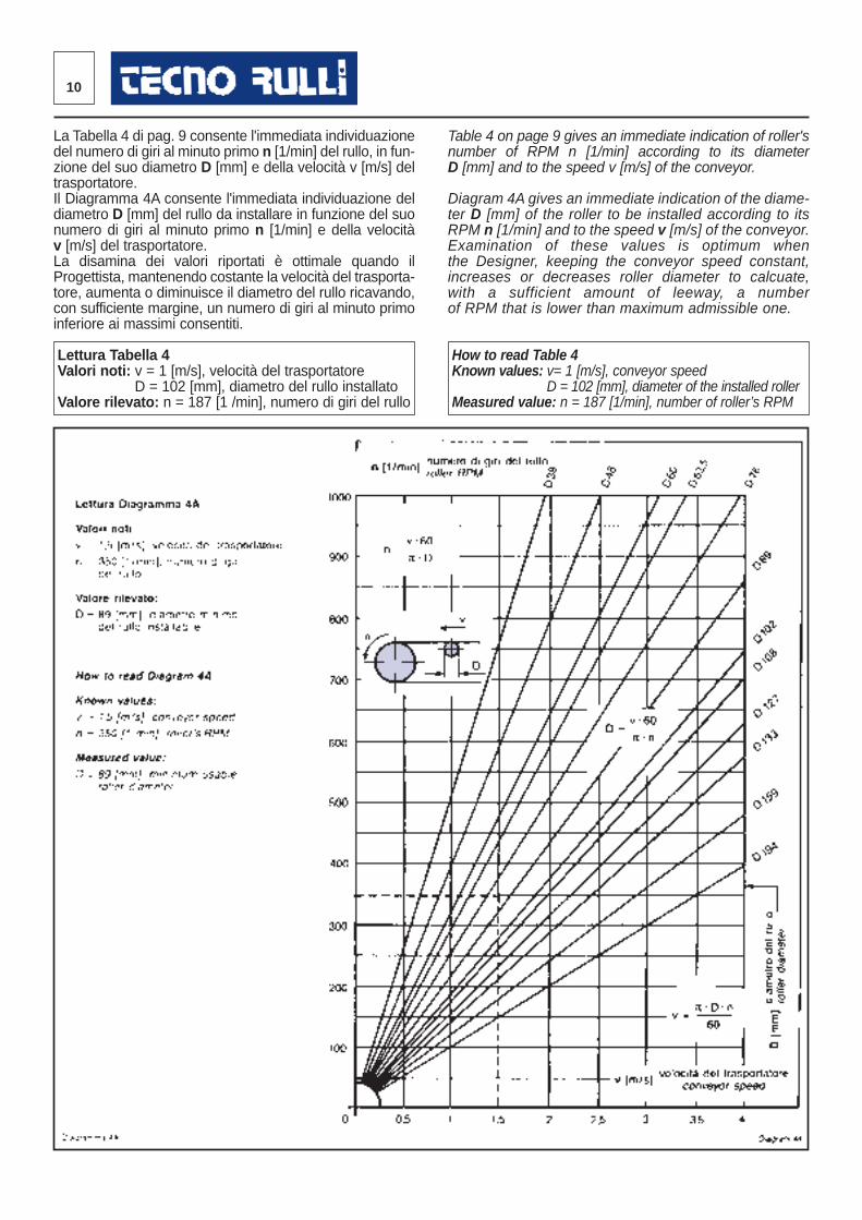
La Tabella 4 di pag. 9 consente l'immediata individuazionedel numero di giri al minuto primo n [1/min] del rullo, in fun-zione del suo diametro D [mm] e della velocità v [m/s] deltrasportatore.Il Diagramma 4A consente l'immediata individuazione deldiametro D [mm] del rullo da installare in funzione del suonumero di giri al minuto primo n [1/min] e della velocitàv [m/s] del trasportatore.La disamina dei valori riportati è ottimale quando ilProgettista, mantenendo costante la velocità del trasporta-tore, aumenta o diminuisce il diametro del rullo ricavando,con sufficiente margine, un numero di giri al minuto primoinferiore ai massimi consentiti.
Lettura Tabella 4Valori noti: v = 1 [m/s], velocità del trasportatore
D = 102 [mm], diametro del rullo installatoValore rilevato: n = 187 [1 /min], numero di giri del rullo
Table 4 on page 9 gives an immediate indication of roller'snumber of RPM n [1/min] according to its diameterD [mm] and to the speed v [m/s] of the conveyor.
Diagram 4A gives an immediate indication of the diame-ter D [mm] of the roller to be installed according to itsRPM n [1/min] and to the speed v [m/s] of the conveyor.Examination of these values is optimum whenthe Designer, keeping the conveyor speed constant,increases or decreases roller diameter to calcuate,with a sufficient amount of leeway, a numberof RPM that is lower than maximum admissible one.
How to read Table 4Known values: v= 1 [m/s], conveyor speed
D = 102 [mm], diameter of the installed rollerMeasured value: n = 187 [1/min], number of roller’s RPM
11®
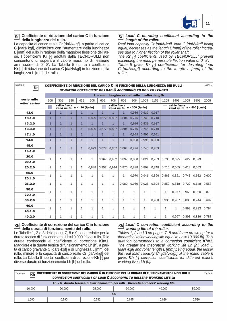
Coefficiente di riduzione del carico C in funzionedella lunghezza del rullo.
La capacità di carico reale Cr [daN≈kgf], a parità di caricoC [daN≈kgf], diminuisce con l'aumentare della lunghezzaL [mm] del rullo in ragione della maggiore flessione dell'as-se. I coefficienti Kr [-] adottati dalla TECNORULLI nonconsentono di superare il valore massimo di flessioneammissibile di 0° 8'. La Tabella 5 riporta i coefficientiKr [-] di riduzione del carico C [daN≈kgf] in funzione dellalunghezza L [mm] del rullo.
Load C de-rating coefficient according to thelength of the roller.
Real load capacity Cr [daN≈kgf], load C [daN≈kgf] beingequal, decreases as the length L [mm] of the roller increa-ses due to higher flection of the roller shaft. The Kr [-] coefficients used by TECNORULLI preventexceeding the max. permissible flection value of 0° 8'.Table 5 gives Kr [-] coefficients for de-rating loadC [daN≈kgf] according to the length L [mm] of theroller.
Coefficiente di correzione del carico C in funzionedella durata di funzionamento del rullo.
Le Tabelle 1, 2 e 3 delle pagg. 7, 8 e 9 sono redatte per ladurata teorica di funzionamento Lh=10.000 [h] del rullo. Taledurata corrisponde al coefficiente di correzione Kh=1.Maggiore è la durata teorica di funzionamento Lh [h], a pari-tà di carico gravante C [daN≈kgf] e di lunghezza L [mm] delrullo, minore è la capacità di carico reale Cr [daN≈kgf] delrullo. La Tabella 6 riporta i coefficienti di correzione Kh [-] perdiverse durate di funzionamento Lh [h] del rullo.
Load C correction coefficient according to theworking lite of thè roller.
Tables 1, 2 and 3 on pages 7, 8 and 9 are drawn up for atheoretical roller working life equal to Lh = 10.000 [h]. Thisduration corresponds to a correction coefficient Kh=1.The greater the theoretical working life Lh [h], load C[daN≈kgf] and roller length L [mm] being equal, the lesserthe real load capacity Cr [daN≈kgf] of the roller. Table 6gives Kh [-] correction coefficients for different roller’sworking lives Lh [h].
COEFFICIENTE DI RIDUZIONE DEL CARICO C IN FUNZIONE DELLA LUNGHEZZA DEI RULLIDE-RATING COEFFICIENT OF LOAD C ACCORDING TO ROLLER LENGTH
serie rulloroller series
L = mm lunghezza del rullo roller length
208 308 388 438 508 608 708 808 908 1008 1158 1258 1408 1608 1808 2008
valido fino a valido fino a valido fino avalid up to valid up to valid up to
13.0 1 1 1 1 1 1 1 1 0,986 0,939 0,917
13.1.0 1 1 1 1 0,899 0,877 0,837 0,804 0,776 0,745 0,710
13.2.0 1 1 1 1 1 1 1 1 0,986 0,939 0,917
13.3.0 1 1 1 1 0,899 0,877 0,837 0,804 0,776 0,745 0,710
17.1.0 1 1 1 1 1 1 1 1 0,998 0,996 0,991
14.0 1 1 1 1 1 1 1 1 0,998 0,996 0,890
15.01 1 1 1 0,899 0,877 0,837 0,804 0,776 0,745 0,709
15.1.0
20.01 1 1 1 1 0,967 0,932 0,897 0,860 0,824 0,769 0,730 0,675 0,622 0,573
20.1.0
20.2.0 1 1 1 1 0,988 0,952 0,914 0,876 0,838 0,807 0,748 0,716 0,665 0,618 0,553
25.01 1 1 1 1 1 1 1 0,970 0,941 0,896 0,866 0,821 0,748 0,662 0,600
25.1.0
25.2.0 1 1 1 1 1 1 1 0,980 0,960 0,925 0,894 0,850 0,818 0,722 0,648 0,558
30.01 1 1 1 1 1 1 1 1 1 1 1 0,977 0,965 0,920 0,870
30.1.0
30.2.0 1 1 1 1 1 1 1 1 1 1 0,968 0,936 0,907 0,883 0,744 0,692
40.01 1 1 1 1 1 1 1 1 1 1 1 1 0,999 0,883 0,794
40.1.0
40.2.0 1 1 1 1 1 1 1 1 1 1 1 1 0,997 0,893 0,836 0,788
Kr
Kr Kr
Tabella 5 Table 5
n = 170 [1/min] n = 300 [1/min] n = 500 [1/min]
COEFFICIENTE DI CORREZIONE DEL CARICO C IN FUNZIONE DELLA DURATA DI FUNZIONAMENTO Lh DEI RULLICORRECTION COEFFICIENT OF LOAD C ACCORDING TO ROLLERS’ WORKING LIFE Lh
Lh = h durata teorica di funzionamento dei rulli theoretical rollers’ working life
10.000 20.000 25.000 30.000 40.000 50.000
Kh
1.000 0,790 0,742 0,695 0,629 0,580
Tabella 6 Table 6Kh
Kh Kh
N
b N
b
N
b
12
Nella progettazione di un trasportatore a nastro, lascelta del tipo di rullo da adottare richiede i seguentidati tecnici:- portata oraria massima Qt [m3/h o t/h] prevista;- natura del materiale M da movimentare quali, massaspecifica γ [t/m3], granulometria o pezzatura p [mm],consistenza (angolo di riposo statico τ° e dinamico disovraccarico ρ°), temperatura T [°C], abrasività, ag -gressività chimica;- larghezza N [mm] e peso Pn [kg/m] del tappeto digomma;- condizioni ambientali e di carico Kc [—] del materialesul tappeto di gomma;- velocità v [m/s] di trasporto del nastro, interasse del lestazioni a rulli superiori (di andata) ls,lg [m] ed in feriori(di ritorno) li [m].
Nei capitoli successivi la TECNORULLI espone la corret-ta procedura di calcolo dell’installazione.
Portata oraria massima del trasportatore
La portata oraria massima Qt [m3/h o t/h] di un trasporta -tore a nastro è determinata: dalla superficie S [m2] dellasezione trasversale teorica del materiale M che insiste sultappeto di gomma N, dalla velocità v [m/s] di trasporto.
Qt = S · v · 3600 [m3/h] ...(2)
oppure
Qt = S · v · 3600 · γ [t/h] ...(3)
dove γ [t/m3] = massa specificadel materiale trasportato
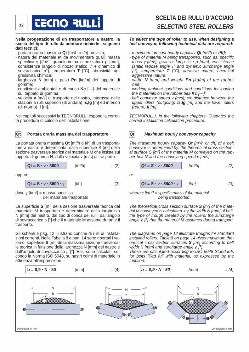
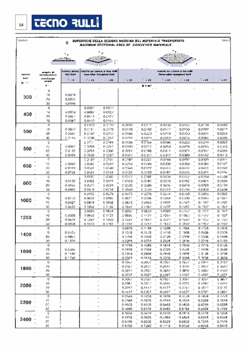
La superficie S [m2] della sezione trasversale teorica delmateriale M trasportato è determinata: dalla larghezzaN [mm] del nastro, dal tipo di conca dei rulli, dall’angolodi sovraccarico ρ [°] che il materiale M assume durante iltrasporto.
Gli schemi a pag. 12 illustrano conche di rulli di installa -zioni correnti. Nella Tabella 8 a pag. 14 sono riportati i va -lori di superficie S [m2] della massima sezione trasversa-le teorica in funzione della larghezza N [mm] del nastro edall’angolo di sovraccarico ρ [°]. Essi sono calcolati, se -condo la Norma ISO 5048, su nastri colmi di materiale inattinenza all’espressione:
b = 0,9 · N - 50 [mm] ...(4)
To select the type of roller to use, when designing abelt conveyor, following technical data are required:
- maximum forecast hourly capacity Qt [m3/h or t/h];- type of material M being transported, such as: specificmass γ [t/m3], grain or lump size p [mm], consistence(static repose angle τ° and dynamic surcharge angleρ°), temperature T [°C], abrasive nature, chemicalaggressive nature;- width N [mm] and weight Pn [kg/m] of the rubberbelt;- working ambient conditions and conditions for loadingthe materials on the rubber belt Kc [—];- belt conveyor speed v [m/s], c/c distance between theupper idlers (outgoing) ls,lg [m] and the lower idlers(return) li [m].
TECNORULLI, in the following chapters, illustrates thecorrect installation calculation procedure.
Maximum hourly conveyor capacity
The maximum hourly capacity Qt [m3/h or t/h] of a beltconveyor is determined by: the theoretical cross section-al surface S [m2] of the material M conveyed on the rub-ber belt N and the conveying speed v [m/s].
Qt = S · v · 3600 [m3/h] ...(2)
or
Qt = S · v · 3600 · γ [t/h] ...(3)
where γ [t/m3] = specific mass of the materialbeing transported
The theoretical cross section surface S [m2] of the mate-rial M conveyed is calculated: by the width N [mm] of belt,the type of trough created by the rollers, the sur chargeangle ρ [°] that the material M assumes during transport.
The diagrams on page 12 illustrate troughs for standardinstalled rollers. Table 8 on page 14 gives maximum the -oretical cross section surfaces S [m2] according to beltwidth N [mm] and surcharge angle ρ [°]. These are calculated according to ISO 5048 Standardsfor belts filled full with material, as expressed by thefunction:
b = 0,9 · N - 50 [mm] ...(4)
Dimensioni in mm Dimensions in mm
SCELTA DEI RULLI D’ACCIAIOSELECTING STEEL ROLLERS
Qt Qt
ANGOLO DI SOVRACCARICO IN FUNZIONE DEI MATERIALI DA TRASPORTARESURCHARGE ANGLE ACCORDING TO THE CONVEYED MATERIALS
natura del materiale da trasportare
type of conveyed material
M
angolo di riposo staticodel materiale
static repose angle ofmaterial
τ[°]
angolo di sovraccarico
surcharge angle
ρ[°]
Materiali molto scorrevoli o pressoché fluidi - materiali granulosi, didimensioni omogenee, secchi o in so spensione, polpe di vegetali,cemento, sabbia silicea secca, ecc.
High flowable or almost fluid materials - granular materials withhomogeneous dimensions, dry or suspended, vegetal pulps,cement, siliceous dry sand, etc.
0 ÷ 18 0
Materiali mediamente scorrevoli - materiali di piccole dimensioniomogenee o secche: semi in rinfusa, fo sfati, cacao, ecc.
Average flowable materials - small size homogeneous or dry mate-rials: bulk, seeds, phosphates, cocoa. etc.
20 ÷ 29 10
Materiali mediamente compattabili, di pezzatura me dia e mista:minerali, pietrisco, carbone fossile, inerti in genere, ecc.
Average compactable materials, of medium and mixed sizes:minerals, rock, coal, inert aggregates in general, etc.
30 ÷ 35 20
Materiali ad alto attrito interno: terre di fonderia, scar ti della lavo-razione del legno, argilla secca, ecc.
Materials with high internai friction: molding sand, wood proces-sing scrap, dry clay, etc.
36 ÷ 45 30
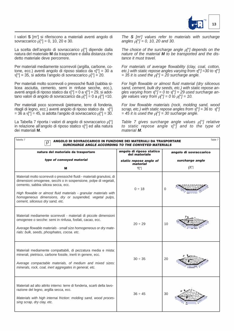
I valori S [m2] si riferiscono a materiali aventi angolo disovraccarico ρ[°] = 0, 10, 20 e 30.
La scelta dell’angolo di sovraccarico ρ[°] dipende dallanatura del materiale M da trasportare e dalla distanza chedetto materiale deve percorrere.
Per materiali mediamente scorrevoli (argilla, carbone, co -tone, ecc.) aventi angolo di riposo statico da τ[°] = 30 aτ[°] = 35, si adotta l’angolo di sovraccarico ρ[°] = 20.
Per materiali molto scorrevoli o pressoché fluidi (sabbia si -licea asciutta, cemento, semi in rinfuse secche, ecc.),aventi angoli di riposo statico da τ[°] = 0 a τ[°] = 29, si adot-tano valori di angolo di sovraccarico da ρ[°] = 0 a ρ[°] =10.
Per materiali poco scorrevoli (pietrame, terre di fonderia,rita gli di legno, ecc.) aventi angolo di riposo statico da τ[°]= 36 a τ[°] = 45, si adotta l’angolo di sovraccarico ρ[°] = 30.
La Tabella 7 riporta i valori di angolo di sovraccarico ρ[°]in relazione all’angolo di riposo statico τ[°] ed alla na turadei materiali M.
The S [m2] values refer to materials with surchargeangles ρ[°] = 0, 10, 20 and 30.
The choice of the surcharge angle ρ[°] depends on thenature of the material M to be transported and the dis-tance it must travel.
For materials of average flowability (clay, coal, cotton,etc.) with static repose angles varying from τ[°] =30 to τ[°]= 35 it is used the ρ[°] = 20 surcharge angle.
For high flowable or almost fluid material (dry siliceoussand, cement, bulk dry seeds, etc.) with static repose an -gles varying from τ[°] = 0 to τ[°] = 29 used surcharge an -gle values vary from ρ[°] = 0 to ρ[°] = 10.
For low flowable materiais (rock, molding sand, woodscrap, etc.) with static repose angles from τ[°] = 36 to τ[°]= 45 it is used the ρ[°] = 30 sucharge angle.
Table 7 gives surcharge angle values ρ[°] rela tiveto static repose angle τ[°] and to the type ofmaterial M.
13®
Tabella 7 Table 7ρ
14
Tabella 8 Table 8
15®
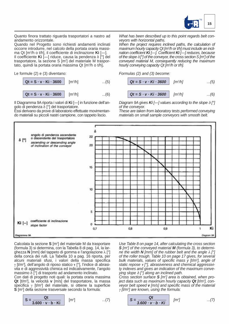
Quanto finora trattato riguarda trasportatori a nastro adandamento orizzontale.Quando nel Progetto sono richiesti andamenti inclinatioc corre introdurre, nel calcolo della portata oraria massi-ma Qt [m3/h o t/h], il coefficiente di inclinazione Ki [—]. Il coefficiente Ki [—] riduce, causa la pendenza δ [°] deltrasportatore, la sezione S [m2] del materiale M traspor -tato, quindi la portata oraria massima Qt [m3/h o t/h].
Le formule (2) e (3) diventano:
Qt = S · v · Ki · 3600 [m3/h] ...(5)
Qt = S · v · Ki · 3600 [m3/h] ...(6)
Il Diagramma 9A riporta i valori di Ki [—] in funzione dell’an-golo di pendenza δ [°] del trasportatore.Essi derivano da prove di laboratorio effettuate movimentan -do materiali su piccoli nastri campione, con tappeto liscio.
What has been described up to this point regards belt con-veyors with horizontal paths.When the project requires inclined paths, the calculation ofmaximum hourly capacity Qt [m3/h or t/h] must include an incli-nation coefficient Ki [—]. Coefficient Ki [—] reduces, becauseof the slope δ [°] of the conveyor, the cross section S [m2] of theconveyed material M, consequently reducing the maximumhourly conveying capacity Qt [m3/h or t/h].
Formulas (2) and (3) become:
Qt = S · v · Ki · 3600 [m3/h] ...(5)
Qt = S · v · Ki · 3600 [m3/h] ...(6)
Diagram 9A gives Ki [—] values according to the slope δ [°]of the conveyor.These are taken from laboratory tests performed conveyingmaterials on small sample conveyors with smooth belt.
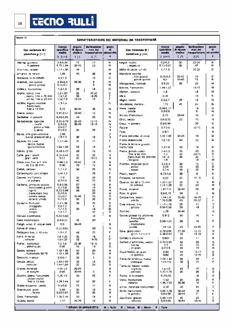
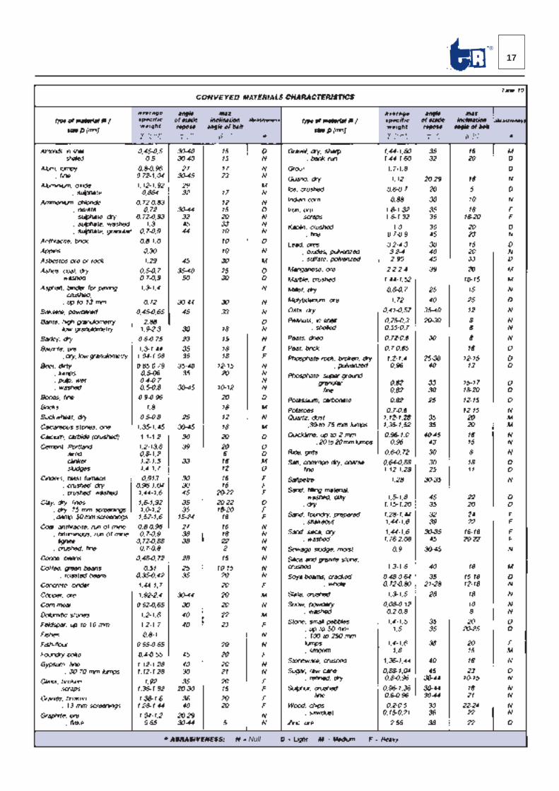
Calcolata la sezione S [m2] del materiale M da trasportare(formula 3) si determina, con la Tabella 8 di pag. 14, la lar -ghezza N [mm] del tappeto di gomma e l’angolazione λ [°]della conca dei rulli. La Tabella 10 a pag. 16 riporta, peralcuni materiali sfusi, i valori della massa specificaγ [t/m3], dell’angolo di riposo statico τ [°], l’indice di abrasi-vita e di aggressività chimica ed indicativamente, l’angolomassimo δ [°] di trasporto ad andamento inclinato.Con dati di progetto noti quali: la portata oraria massimaQt [t/m3], la velocità v [m/s] del trasportatore, la massaspecifica γ [t/m3] del materiale, si ottiene la superficieS [m2] della sezione trasversale secondo la formula:
S = Qt [m2] ...(7)3.600 · v · b · Ki
Use Table 8 on page 14, after calculating the cross sectionS [m2] of the conveyed material M (formula 3), to determi-ne the width N [mm] of the rubber belt and the angle λ [°]of the roller trough. Table 10 on page 17 gives, for severalbulk materials, values of specific mass y [t/m3], angle ofstatic repose τ [°], abrasiveness and chemical aggressivi-ty indexes and gives an indication of the maximum conve-ying slope δ [°] along an inclined path. Cross section surface S [m2] area is obtained, when pro-ject data such as maximum hourly capacity Qt [t/m3], con-veyor belt speed v [m/s] and specific mass of the materialγ [t/m3] are known, using the formula:
S = Qt [m2] ...(7)3.600 · v · b · Ki
16
17®
Null
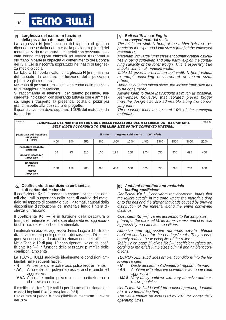
Larghezza del nastro in funzione della pezzatura del materiale
La larghezza N [mm] minima del tappeto di gommadipende anche dalla natura e dalla pezzatura p [mm] delmateriale M da trasportare. I materiali con pezzatura ele-vata hanno mag giore difficoltà ad essere trasportati esfruttano in parte la ca pacità di contenimento della concadei rulli. Ciò si riscontra soprattutto nei nastri di larghez-za medio-piccola. La Tabella 11 riporta i valori di larghezza N [mm] minimadel tappeto da adottare in funzione della pezzaturap [mm] vagliata o mista.Nel caso di pezzatura mista si tiene conto della pezzatu -ra di maggiore dimensione.Si raccomanda di attenersi, per quanto possibile, allesud dette indicazioni considerando tuttavia che è ammes-sa, lungo il trasporto, la presenza isolata di pezzi piùgrandi rispetto alla pezzatura di progetto. Il quantitativo non deve superare il 10% del materiale datrasportare.
Coefficiente di condizione ambientale e di carico del materiale
II coefficiente Kc [—] prende in esame i carichi acciden -tali che i rulli supportano nella zona di caduta del mate -riale sul tappeto di gomma e quelli alternati, causati dalladiscontinua distribuzione del materiale lungo l’intera di -stanza di trasporto.
Il coefficiente Kc [—] è in funzione della pezzatura p[mm] del materiale M, della sua abrasività ed aggressivi-tà chi mica, delle condizioni ambientali.
I materiali abrasivi ed aggressivi danno luogo a difficili con -dizioni ambientali per le protezioni dei cuscinetti. Di conse -guenza riducono la durata di funzionamento dei rulli. Nella Tabella 12 di pag. 19 sono riportati i valori del coef -ficiente Kc [—] in funzione delle pezzature p [mm] e del lecondizioni ambientali.
La TECNORULLI suddivide idealmente le condizioni am -bientali nelle seguenti fasce:- N Ambiente anche polveroso, pulito regolarmente.- AA Ambiente con polveri abrasive, anche umide ed
aggressive.- MAA Ambiente molto polveroso con particelle molto
abrasive e corrosive.
Il coefficiente Kc [—] è valido per durate di funzionamen -to degli impianti F = 12 ore/giorno [h/d]. Per durate superiori è consigliabile aumentarne il valoredel 20%.
Belt width according to conveyed material’s size
The minimum width N [mm] of the rubber belt also de-pends on the type and lump size p [mm] of the conveyedmaterial M. Materials with large lump sizes encounter greater difficul-ties in being conveyed and only partly exploit the contai-ning capacity of the roller trough. This is especially truein belts with small-medium width. Table 11 gives the minimum belt width N [mm] valuesto adopt according to screened or mixed sizesp [mm].When calculating mixed sizes, the largest lump size hasto be considered.AIways keep to these instructions as much as possible. Remember, however, that isolated pieces biggerthan the design size are admissible along the conve-ying path.This quantity must not exceed 10% of the conveyedmaterials.
Ambient condition and materials loading coefficient
Coefficient Kc [—] considers the accidental loads thatthe rollers sustain in the zone where the materials droponto the belt and the alternating loads caused by unevendistribution of the material along the entire convey ingdistance.
Coefficient Kc [—] varies according to the lump sizep [mm] of the material M, its abrasiveness and chemicalaggressivity and ambient conditions.
Abrasive and aggressive materials create difficultambient conditions for the bearings’ seals. They conse-quently reduce the working life of the rollers. Table 12 on page 19 gives Kc [—] coefficient values ac -cording to materials lump sizes p [mm] and ambient con -ditions.
TECNORULLI subdivides ambient conditions into the fol-lowing ranges:- N Dusty ambient but cleaned at regular intervals.- AA Ambient with abrasive powders, even humid and
aggressive.- MAA Very dusty ambient with very abrasive and cor -
rosive particles.
Coefficient Kc [—] is valid for a plant operating durationof F = 12 hours/day [h/d].The value should be increased by 20% for longer dailyoperating times.
LARGHEZZA DEL NASTRO IN FUNZIONE DELLA PEZZATURA DEL MATERIALE DA TRASPORTAREBELT WIDTH ACCORDING TO THE LUMP SIZE OF THE CONVEYED MATERIAL
pezzatura del materialelump sizep = [mm]
N = mm larghezza del nastro belt width
400 500 650 800 1000 1200 1400 1600 1800 2000 2200
pezzatura vagliatauniforme
uniform screened lump size
50 75 115 150 175 250 275 350 350 425 450
pezzatura mista
mixed lump size
100 150 200 300 400 500 525 650 700 750 800
18
N N
Kc Kc
Tabella 11 Table 11
19®
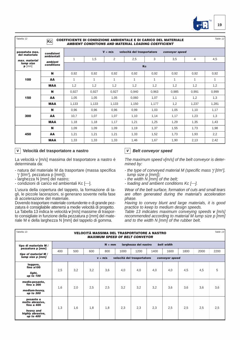
Velocità del trasportatore a nastro
La velocità v [m/s] massima del trasportatore a nastro èdeterminata da:
- natura del materiale M da trasportare (massa specifi caγ [t/m3], pezzatura p [mm]);- larghezza N [mm] del nastro;- condizioni di carico ed ambientali Kc [⎯].
L’usura della copertura del tappeto, la formazione di ta -gli, le piccole lacerazioni, si generano sovente nella fasedi accelerazione del materiale.Dovendo trasportare materiale contundente e di grande pez -zatura è consigliabile attenersi a medie velocità di progetto.La Tabella 13 indica le velocità v [m/s] massime di traspor -to consigliate in funzione della pezzatura p [mm] del mate -riale M e della larghezza N [mm] del tappeto di gomma.
Belt conveyor speed
The maximum speed v[m/s] of the belt conveyor is deter-mined by:
- the type of conveyed material M (specific mass γ [t/m3],lump size p [mm]);- the width N [mm] of the belt;- loading and ambient conditions Kc [⎯].
Wear of the belt surface, formation of cuts and small tearsare often generated during the material’s accelerationphase.Having to convey blunt and large materials, it is goodpractice to keep to medium design speeds. Table 13 indicates maximum conveying speeds v [m/s]recommended according to material M lump size p [mm]and to the width N [mm] of the rubber belt.
COEFFICIENTE DI CONDIZIONE AMBIENTALE E DI CARICO DEL MATERIALEAMBIENT CONDITIONS AND MATERIAL LOADING COEFFICIENT
pezzatuta max.del materiale
max. materiallump sizep [mm]
condizioniambientali
ambientconditions
V = m/s velocità del trasportatore conveyor speed
1 1,5 2 2,5 3 3,5 4 4,5
Kc
100
N 0,92 0,92 0,92 0,92 0,92 0,92 0,92 0,92
AA 1 1 1 1 1 1 1 1
MAA 1,2 1,2 1,2 1,2 1,2 1,2 1,2 1,2
150
N 0,927 0,927 0,927 0,940 0,963 0,985 0,991 0,999
AA 1,05 1,05 1,05 0,060 1,07 1,1 1,2 1,3
MAA 1,133 1,133 1,133 1,150 1,177 1,2 1,237 1,281
300
N 0,96 0,96 0,96 0,99 1,03 1,05 1,10 1,17
AA 10,7 1,07 1,07 1,10 1,14 1,17 1,23 1,3
MAA 1,18 1,18 1,17 1,21 1,25 1,29 1,35 1,43
450
N 1,09 1,09 1,09 1,19 1,37 1,55 1,73 1,98
AA 1,21 1,21 1,21 1,33 1,52 1,73 1,93 2,2
MAA 1,33 1,33 1,33 1,46 1,67 1,90 2,13 2,42
VELOCITÀ MASSIMA DEL TRASPORTATORE A NASTROMAXIMUM SPEED OF BELT CONVEYOR
tipo di materiale M /pezzatura p [mm]
tipe of material M /lump size p [mm]
N = mm larghezza del nastro belt width
400 500 600 800 1000 1200 1400 1600 1800 2000 2200
v = m/s velocità del trasportatore conveyor speed
leggero,fino a100
light,up to 100
2,5 3,2 3,2 3,6 4,0 4,0 4,0 4,0 4,5 4,5 5
medio-pesante,fino a 300
medium-heavy,up to 300
1,6 2,0 2,5 2,5 3,2 3,2 3,2 3,6 3,6 3,6 3,6
pesante emolto abrasivo,
fino a 400
heavy andhighly abrasive,
up to 400
1,3 1,6 1,8 1,8 2,3 2,3 2,3 2,5 2,5 2,5 2,5
Tabella 12 Table 12Kc
Tabella 13 Table 13
v v
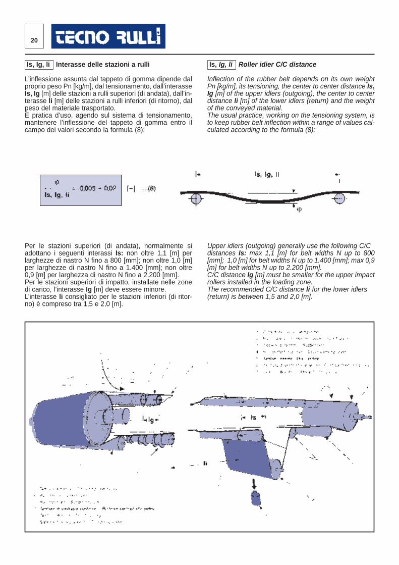
Is, Ig, li Roller idier C/C distance
Inflection of the rubber belt depends on its own weightPn [kg/m], its tensioning, the center to center distance Is,Ig [m] of the upper idlers (outgoing), the center to centerdistance li [m] of the lower idlers (return) and the weightof the conveyed material. The usual practice, working on the tensioning system, isto keep rubber belt inflection within a range of values cal-culated according to the formula (8):
Upper idlers (outgoing) generally use the following C/Cdistances Is: max 1,1 [m] for belt widths N up to 800[mm]; 1,0 [m] for belt widths N up to 1.400 [mm]; max 0,9[m] for belt widths N up to 2.200 [mm].C/C distance Ig [m] must be smaller for the upper impactrollers installed in the loading zone.The recommended C/C distance li for the lower idlers(return) is between 1,5 and 2,0 [m].
Is, Ig, li Interasse delle stazioni a rulli
L’inflessione assunta dal tappeto di gomma dipende dalproprio peso Pn [kg/m], dal tensionamento, dall’interasseIs, Ig [m] delle stazioni a rulli superiori (di andata), dall’in-terasse li [m] delle stazioni a rulli inferiori (di ritorno), dalpeso del materiale trasportato. È pratica d’uso, agendo sul sistema di tensionamento,mantenere l’inflessione del tappeto di gomma entro ilcam po dei valori secondo la formula (8):
Per le stazioni superiori (di andata), normalmente siadot tano i seguenti interassi Is: non oltre 1,1 [m] perlarghez ze di nastro N fino a 800 [mm]; non oltre 1,0 [m]per larghezze di nastro N fino a 1.400 [mm]; non oltre0,9 [m] per larghezza di nastro N fino a 2.200 [mm]. Per le stazioni superiori di impatto, installate nelle zonedi carico, l’interasse Ig [m] deve essere minore. L’interasse li consigliato per le stazioni inferiori (di ritor -no) è compreso tra 1,5 e 2,0 [m].
20
21®
PESO MEDIO LINEARE DEL TAPPETO PER TRASPORTATORI A NASTROAVERAGE LINEAR WEIGHT OF BELTS FOR BELT CONVEYORS
N = mm larghezza del nastro belt width
400 500 650 800 1000 1200 1400 1600 1800 2000 2200
Pn = kg/m peso del tappeto belt weight
3,5 ÷ 5 4,4 ÷ 6 5,2 ÷ 7,5 7,7 ÷ 10,5 12,3 ÷ 15,5 16,5 ÷ 20 19 ÷ 24 23 ÷ 28 25 ÷ 31,5 28,5 ÷ 37 31,2 ÷ 39,8
Tabella 14 Table 14
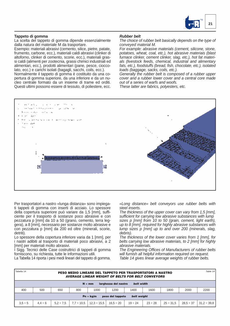
Tappeto di gommaLa scelta del tappeto di gomma dipende essenzialmentedalla natura del materiale M da trasportare.Esempio: materiali abrasivi (cemento, silice, pietre, patate,frumento, carbone, ecc.), materiali caldi abrasivi (clinker dialtoforno, clinker di cemento, scorie, ecc.), materiali gras-si caldi (alimenti per zootecnia, grassi chimici industriali edali mentari, ecc.), prodotti alimentari (pane, pesce, ciocco-lato, ecc.) e carichi isolati (bagagli, sacchi, coils, ecc.).Normalmente il tappeto di gomma è costituito da una co -pertura di gomma superiore, da una inferiore e da un nu -cleo centrale formato da un insieme di trame ed orditi.Questi ultimi possono essere di tessuto, di poliestere, ecc.
Per trasportatori a nastro «lunga distanza» sono impiega-ti tap peti di gomma con inserti di acciaio. Lo spessoredella copertura superiore può variare da 1,5 [mm], suffi-ciente per il trasporto di sostanze poco abrasive e conpezzatura p [mm] da 10 a 50 (grano, cemento, terra leg-gera), a 8 [mm], necessario per sostanze molto abrasive econ pezzatura p [mm] da 200 ed oltre (minerali, scorie,detriti).Lo spessore della copertura inferiore varia da 1 [mm], peri nastri adibiti al trasporto di materiali poco abrasivi, a 2[mm] per materiali molto abrasivi.I Sigg. Tecnici delle Case costruttrici di tappeti di gommafor niscono, su richiesta, tutte le informazioni utili. La Tabella 14 riporta i pesi medi lineari del tappeto di gomma.
Rubber beltThe choice of rubber belt basically depends on the type ofconveyed material M. For example: abrasive materials (cement, silicone, stone,potatoes, wheat, coal, etc.), hot abrasive materiais (blastfurnace clinker, cement clinker, slag, etc.), hot fat materi -als (livestock feeds, chemical, industrial and alimentaryfats, etc.), foodstuffs (bread, fish, chocolate, etc.), isolatedloads (baggage, sacks, coils, etc.).Generally the rubber belt is composed of a rubber uppercover and a rubber lower cover and a central core madeout of a series of warfs and woofs. These latter are fabrics, polyesters, etc.
«Long distance» belt conveyors use rubber belts withsteel inserts.The thickness of the upper cover can vary from 1,5 [mm],sufficient for carrying low abrasive substances with lumpsizes p [mm] from 10 to 50 (grain, cement, light earth),up to 8 [mm], required for highly abrasive substances withlump sizes p [mm] up to and over 200 (minerals, slag,debris).The thickness of the lower cover varies from 1 [mm], forbelts carrying low abrasive materiais, to 2 [mm] for highlyabrasive materials.The Engineering Offices of Manufacturers of rubber beltswill furnish all helpful information required on request.Table 14 gives linear average weights of rubber belts.
22
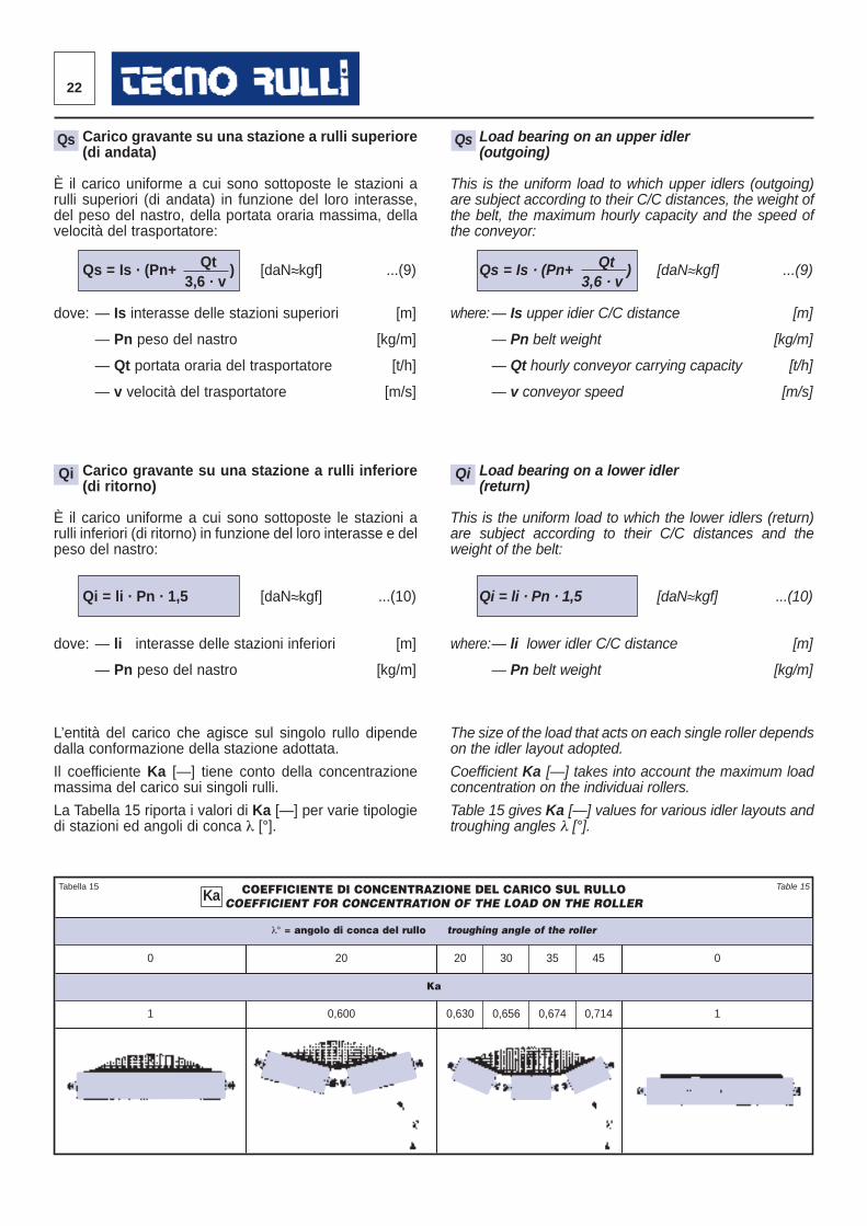
Carico gravante su una stazione a rulli superiore(di andata)
È il carico uniforme a cui sono sottoposte le stazioni arulli superiori (di andata) in funzione del loro interasse,del peso del nastro, della portata oraria massima, dellavelocità del trasportatore:
QtQs = Is · (Pn+ ) [daN≈kgf] ...(9)3,6 · v
dove: — Is interasse delle stazioni superiori [m]
— Pn peso del nastro [kg/m]
— Qt portata oraria del trasportatore [t/h]
— v velocità del trasportatore [m/s]
Carico gravante su una stazione a rulli inferiore(di ritorno)
È il carico uniforme a cui sono sottoposte le stazioni arulli inferiori (di ritorno) in funzione del loro interasse e delpe so del nastro:
Qi = li · Pn · 1,5 [daN≈kgf] ...(10)
dove: — li interasse delle stazioni inferiori [m]
— Pn peso del nastro [kg/m]
L’entità del carico che agisce sul singolo rullo dipendedal la conformazione della stazione adottata.
Il coefficiente Ka [—] tiene conto della concentrazionemassima del carico sui singoli rulli.
La Tabella 15 riporta i valori di Ka [—] per varie tipologiedi stazioni ed angoli di conca λ [°].
Load bearing on an upper idler (outgoing)
This is the uniform load to which upper idlers (outgoing)are subject according to their C/C distances, the weight ofthe belt, the maximum hourly capacity and the speed ofthe conveyor:
QtQs = Is · (Pn+ ) [daN≈kgf] ...(9)3,6 · v
where:— Is upper idier C/C distance [m]
— Pn belt weight [kg/m]
— Qt hourly conveyor carrying capacity [t/h]
— v conveyor speed [m/s]
Load bearing on a lower idler(return)
This is the uniform load to which the lower idlers (return)are subject according to their C/C distances and theweight of the belt:
Qi = li · Pn · 1,5 [daN≈kgf] ...(10)
where:— li lower idler C/C distance [m]
— Pn belt weight [kg/m]
The size of the load that acts on each single roller dependson the idler layout adopted.
Coefficient Ka [—] takes into account the maximum loadconcentration on the individuai rollers.
Table 15 gives Ka [—] values for various idler layouts andtroughing angles λ [°].
COEFFICIENTE DI CONCENTRAZIONE DEL CARICO SUL RULLOCOEFFICIENT FOR CONCENTRATION OF THE LOAD ON THE ROLLER
λ° = angolo di conca del rullo troughing angle of the roller
0 20 20 30 35 45 0
Ka
1 0,600 0,630 0,656 0,674 0,714 1
Qs Qs
Qi Qi
Tabella 15 Table 15Ka
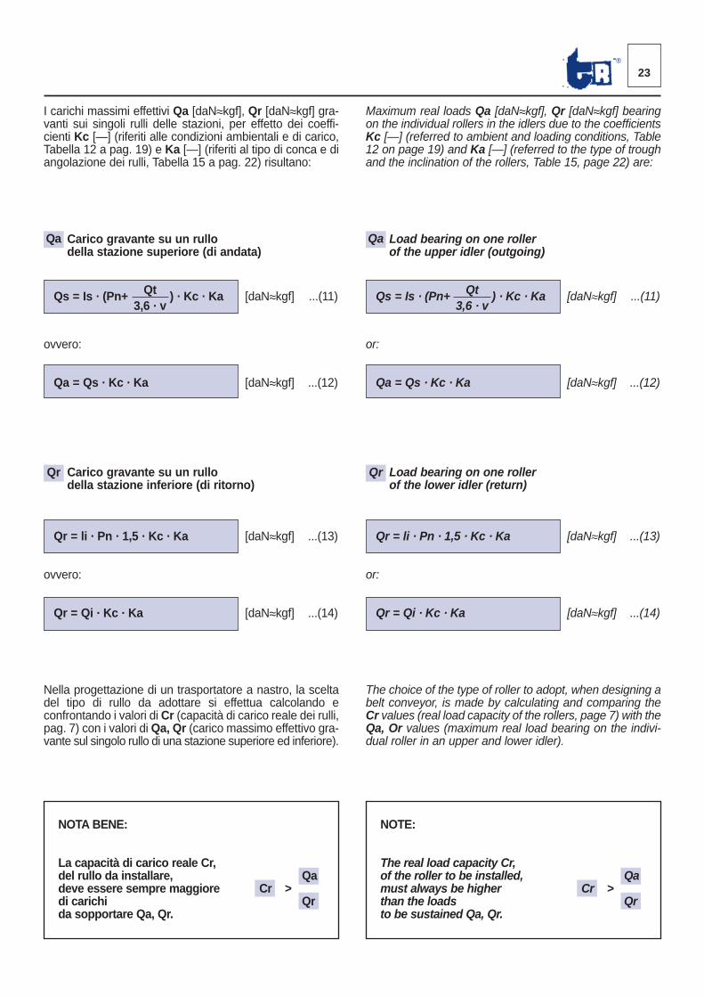
Maximum real loads Qa [daN≈kgf], Qr [daN≈kgf] bearingon the individual rollers in the idlers due to the coefficientsKc [—] (referred to ambient and loading conditions, Table12 on page 19) and Ka [—] (referred to the type of troughand the inclination of the rollers, Table 15, page 22) are:
Load bearing on one rollerof the upper idler (outgoing)
QtQs = Is · (Pn+ ) · Kc · Ka [daN≈kgf] ...(11)3,6 · v
or:
Qa = Qs · Kc · Ka [daN≈kgf] ...(12)
Load bearing on one rollerof the lower idler (return)
Qr = li · Pn · 1,5 · Kc · Ka [daN≈kgf] ...(13)
or:
Qr = Qi · Kc · Ka [daN≈kgf] ...(14)
The choice of the type of roller to adopt, when designing abelt conveyor, is made by calculating and comparing theCr values (real load capacity of the rollers, page 7) with theQa, Or values (maximum real load bear ing on the indivi-dual roller in an upper and lower idler).
I carichi massimi effettivi Qa [daN≈kgf], Qr [daN≈kgf] gra -vanti sui singoli rulli delle stazioni, per effetto dei coeffi -cienti Kc [—] (riferiti alle condizioni ambientali e di carico,Tabella 12 a pag. 19) e Ka [—] (riferiti al tipo di conca e diangolazione dei rulli, Tabella 15 a pag. 22) risultano:
Carico gravante su un rullodella stazione superiore (di andata)
QtQs = Is · (Pn+ ) · Kc · Ka [daN≈kgf] ...(11)3,6 · v
ovvero:
Qa = Qs · Kc · Ka [daN≈kgf] ...(12)
Carico gravante su un rullodella stazione inferiore (di ritorno)
Qr = li · Pn · 1,5 · Kc · Ka [daN≈kgf] ...(13)
ovvero:
Qr = Qi · Kc · Ka [daN≈kgf] ...(14)
Nella progettazione di un trasportatore a nastro, la sceltadel tipo di rullo da adottare si effettua calcolando econfron tando i valori di Cr (capacità di carico reale dei rulli,pag. 7) con i valori diQa, Qr (carico massimo effettivo gra-vante sul singolo rullo di una stazione superiore ed inferiore).
23®
NOTA BENE:
La capacità di carico reale Cr,del rullo da installare, Qadeve essere sempre maggiore Cr >di carichi Qrda sopportare Qa, Qr.
NOTE:
The real load capacity Cr,of the roller to be installed, Qamust always be higher Cr >than the loads Qrto be sustained Qa, Qr.
Qa Qa
Qr Qr
24
ESEMPIO DI CALCOLOSAMPLE CALCULATION
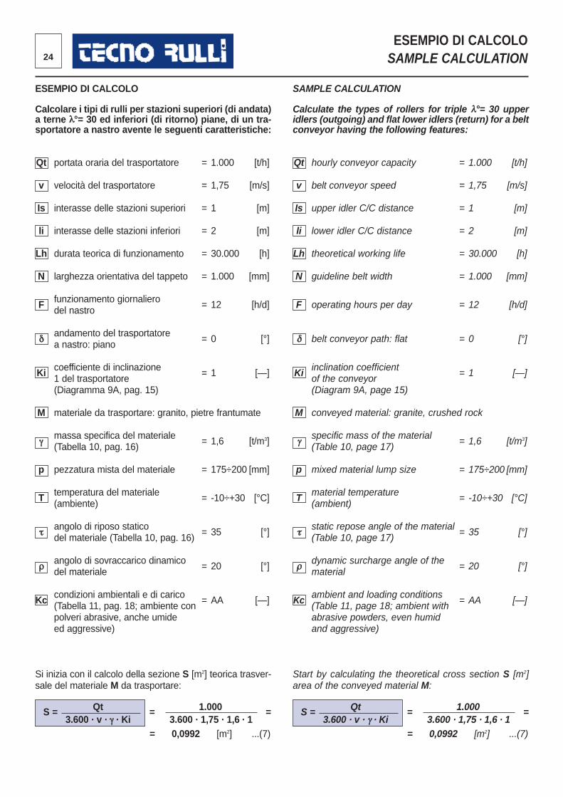
ESEMPIO DI CALCOLO
Calcolare i tipi di rulli per stazioni superiori (di andata)a terne λ°= 30 ed inferiori (di ritorno) piane, di un tra -sportatore a nastro avente le seguenti caratteristiche:
Qt portata oraria del trasportatore = 1.000 [t/h]
v velocità del trasportatore = 1,75 [m/s]
Is interasse delle stazioni superiori = 1 [m]
li interasse delle stazioni inferiori = 2 [m]
Lh durata teorica di funzionamento = 30.000 [h]
N larghezza orientativa del tappeto = 1.000 [mm]
F funzionamento giornaliero del nastro = 12 [h/d]
δandamento del trasportatorea nastro: piano = 0 [°]
Ki coefficiente di inclinazione = 1 [—]1 del trasportatore (Diagramma 9A, pag. 15)
M materiale da trasportare: granito, pietre frantumate
γmassa specifica del materiale(Tabella 10, pag. 16) = 1,6 [t/m3]
p pezzatura mista del materiale = 175÷200 [mm]
T temperatura del materiale(ambiente) = -10÷+30 [°C]
τangolo di riposo statico = 35 [°] del materiale (Tabella 10, pag. 16)
ρangolo di sovraccarico dinamico = 20 [°] del materiale
Kc condizioni ambientali e di carico = AA [—](Tabella 11, pag. 18; ambiente conpolveri abrasive, anche umide ed aggressive)
Si inizia con il calcolo della sezione S [m2] teorica trasver -sale del materiale M da trasportare:
Qt 1.000S = = =3.600 · v · γ · Ki 3.600 · 1,75 · 1,6 · 1
= 0,0992 [m2] ...(7)
SAMPLE CALCULATION
Calculate the types of rollers for triple λ°= 30 upperidlers (outgoing) and flat lower idlers (return) for a beltconveyor having the following features:
Qt hourly conveyor capacity = 1.000 [t/h]
v belt conveyor speed = 1,75 [m/s]
Is upper idler C/C distance = 1 [m]
li lower idler C/C distance = 2 [m]
Lh theoretical working life = 30.000 [h]
N guideline belt width = 1.000 [mm]
F operating hours per day = 12 [h/d]
δ belt conveyor path: flat = 0 [°]
Ki inclination coefficient = 1 [—]of the conveyor(Diagram 9A, page 15)
M conveyed material: granite, crushed rock
γspecific mass of the material(Table 10, page 17) = 1,6 [t/m3]
p mixed material lump size = 175÷200 [mm]
T material temperature(ambient) = -10÷+30 [°C]
τstatic repose angle of the material = 35 [°] (Table 10, page 17)
ρdynamic surcharge angle of the = 20 [°] material
Kc ambient and loading conditions = AA [—](Table 11, page 18; ambient withabrasive powders, even humidand aggressive)
Start by calculating the theoretical cross section S [m2]area of the conveyed material M:
Qt 1.000S = = =3.600 · v · γ · Ki 3.600 · 1,75 · 1,6 · 1
= 0,0992 [m2] ...(7)
25®
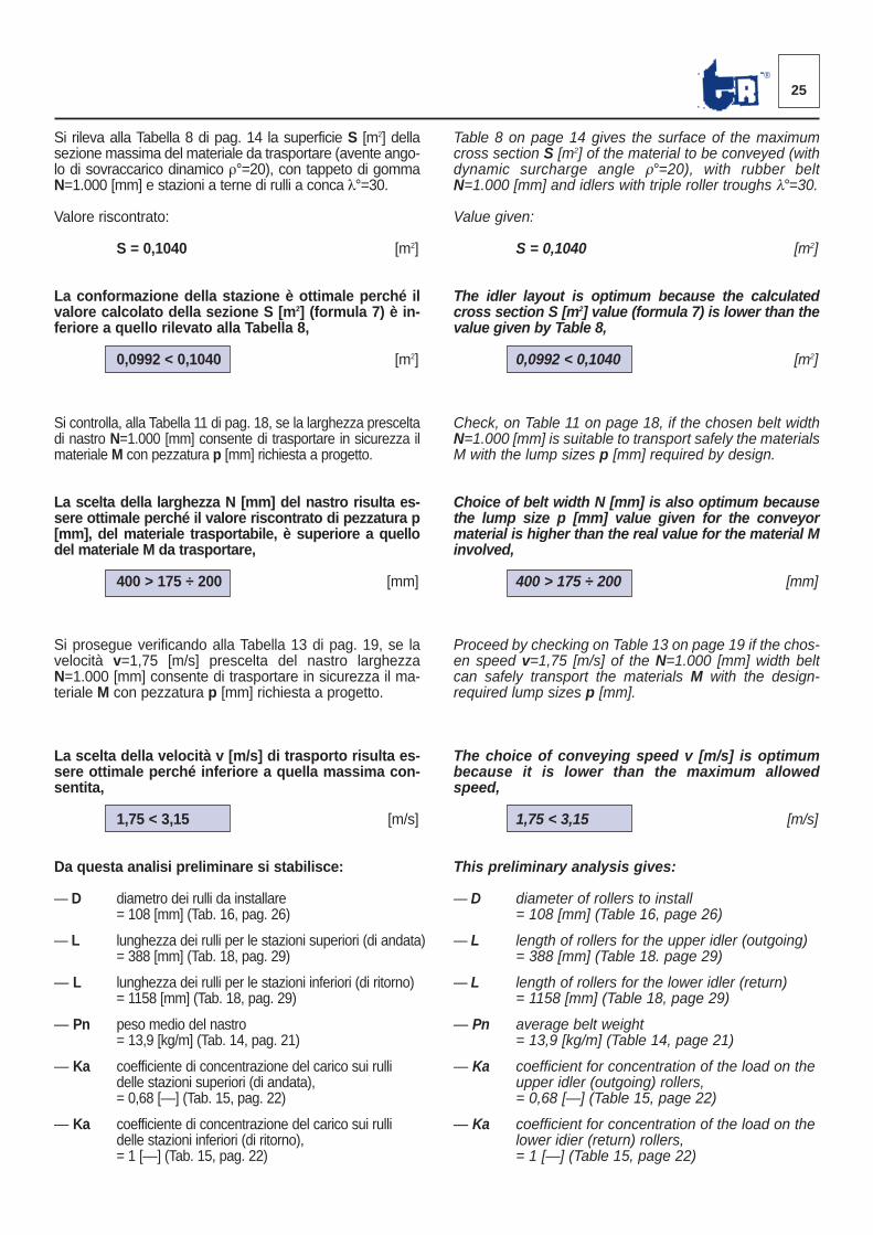
Si rileva alla Tabella 8 di pag. 14 la superficie S [m2] dellasezione massima del materiale da trasportare (avente ango -lo di sovraccarico dinamico ρ°=20), con tappeto di gommaN=1.000 [mm] e stazioni a terne di rulli a conca λ°=30.
Valore riscontrato:
S = 0,1040 [m2]
La conformazione della stazione è ottimale perché ilvalore calcolato della sezione S [m2] (formula 7) è in -feriore a quello rilevato alla Tabella 8,
0,0992 < 0,1040 [m2]
Si controlla, alla Tabella 11 di pag. 18, se la larghezza presceltadi nastro N=1.000 [mm] consente di trasportare in sicurezza ilmateriale M con pezzatura p [mm] richiesta a progetto.
La scelta della larghezza N [mm] del nastro risulta es -sere ottimale perché il valore riscontrato di pezzatura p[mm], del materiale trasportabile, è superiore a quellodel materiale M da trasportare,
400 > 175 ÷ 200 [mm]
Si prosegue verificando alla Tabella 13 di pag. 19, se lavelocità v=1,75 [m/s] prescelta del nastro larghezzaN=1.000 [mm] consente di trasportare in sicurezza il ma -teriale M con pezzatura p [mm] richiesta a progetto.
La scelta della velocità v [m/s] di trasporto risulta es -sere ottimale perché inferiore a quella massima con -sentita,
1,75 < 3,15 [m/s]
Da questa analisi preliminare si stabilisce:
— D diametro dei rulli da installare = 108 [mm] (Tab. 16, pag. 26)
— L lunghezza dei rulli per le stazioni superiori (di andata)= 388 [mm] (Tab. 18, pag. 29)
— L lunghezza dei rulli per le stazioni inferiori (di ritorno) = 1158 [mm] (Tab. 18, pag. 29)
— Pn peso medio del nastro= 13,9 [kg/m] (Tab. 14, pag. 21)
— Ka coefficiente di concentrazione del carico sui rulli delle stazioni superiori (di andata), = 0,68 [—] (Tab. 15, pag. 22)
— Ka coefficiente di concentrazione del carico sui rulli delle stazioni inferiori (di ritorno), = 1 [—] (Tab. 15, pag. 22)
Table 8 on page 14 gives the surface of the maximumcross section S [m2] of the material to be conveyed (withdynamic surcharge angle ρ°=20), with rubber beltN=1.000 [mm] and idlers with triple roller troughs λ°=30.
Value given:
S = 0,1040 [m2]
The idler layout is optimum because the calculatedcross section S [m2] value (formula 7) is lower than thevalue given by Table 8,
0,0992 < 0,1040 [m2]
Check, on Table 11 on page 18, if the chosen belt widthN=1.000 [mm] is suitable to transport safely the materialsM with the lump sizes p [mm] required by design.
Choice of belt width N [mm] is also optimum becausethe lump size p [mm] value given for the conveyormaterial is higher than the real value for the material Minvolved,
400 > 175 ÷ 200 [mm]
Proceed by checking on Table 13 on page 19 if the chos -en speed v=1,75 [m/s] of the N=1.000 [mm] width beltcan safely transport the materials M with the design-required lump sizes p [mm].
The choice of conveying speed v [m/s] is optimumbecause it is lower than the maximum allowedspeed,
1,75 < 3,15 [m/s]
This preliminary analysis gives:
— D diameter of rollers to install= 108 [mm] (Table 16, page 26)
— L length of rollers for the upper idler (outgoing) = 388 [mm] (Table 18. page 29)
— L length of rollers for the lower idler (return) = 1158 [mm] (Table 18, page 29)
— Pn average belt weight= 13,9 [kg/m] (Table 14, page 21)
— Ka coefficient for concentration of the load on the upper idler (outgoing) rollers, = 0,68 [—] (Table 15, page 22)
— Ka coefficient for concentration of the load on the lower idier (return) rollers,= 1 [—] (Table 15, page 22)
26
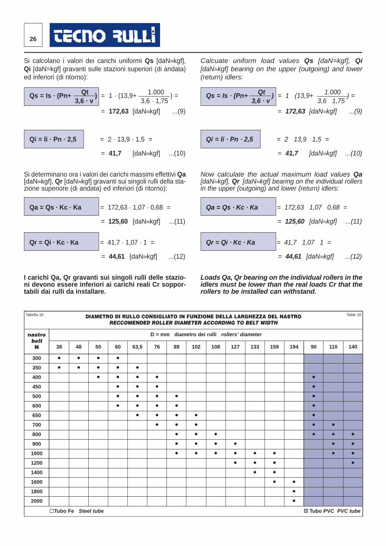
Si calcolano i valori dei carichi uniformi Qs [daN≈kgf],Qi [daN=kgf] gravanti sulle stazioni superiori (di andata)ed inferiori (di ritorno):
Qt 1.000Qs = Is · (Pn+ ) = 1 · (13,9+ ) =3,6 · v 3,6 · 1,75
= 172,63 [daN≈kgf] ...(9)
Qi = li · Pn · 2,5 = 2 · 13,9 · 1,5 =
= 41,7 [daN≈kgf] ...(10)
Si determinano ora i valori dei carichi massimi effettivi Qa[daN≈kgf], Qr [daN≈kgf] gravanti sui singoli rulli della sta-zione superiore (di andata) ed inferiori (di ritorno):
Qa = Qs · Kc · Ka = 172,63 · 1,07 · 0,68 =
= 125,60 [daN≈kgf] ...(11)
Qr = Qi · Kc · Ka = 41,7 · 1,07 · 1 =
= 44,61 [daN≈kgf] ...(12)
I carichi Qa, Qr gravanti sui singoli rulli delle stazio-ni devono essere inferiori ai carichi reali Cr soppor-tabili dai rulli da installare.
Calcuate uniform load values Qs [daN=kgf], Qi[daN≈kgf] bearing on the upper (outgoing) and lower(return) idlers:
Qt 1.000Qs = Is · (Pn+ ) = 1 · (13,9+ ) =3,6 · v 3,6 · 1,75
= 172,63 [daN≈kgf] ...(9)
Qi = li · Pn · 2,5 = 2 · 13,9 · 1,5 =
= 41,7 [daN≈kgf] ...(10)
Now calculate the actual maximum load values Qa[daN≈kgf], Qr [daN≈kgf] bearing on the individual rollersin the upper (outgoing) and lower (return) idlers:
Qa = Qs · Kc · Ka = 172,63 · 1,07 · 0,68 =
= 125,60 [daN≈kgf] ...(11)
Qr = Qi · Kc · Ka = 41,7 · 1,07 · 1 =
= 44,61 [daN≈kgf] ...(12)
Loads Qa, Qr bearing on the individual rollers in theidlers must be lower than the real loads Cr that therollers to be installed can withstand.
DIAMETRO DI RULLO CONSIGLIATO IN FUNZIONE DELLA LARGHEZZA DEL NASTRORECCOMENDED ROLLER DIAMETER ACCORDING TO BELT WIDTH
nastrobeltN
D = mm diametro dei rulli rollers’ diameter
38 48 50 60 63,5 76 89 102 108 127 133 159 194 90 110 140
300 • • • •350 • • • • •400 • • • • •450 • • • •500 • • • • •600 • • • • •650 • • • • •700 • • • • •800 • • • • • •900 • • • • • •1000 • • • • • • • •1200 • • • •1400 • •1600 • •1800 •2000 •
Tubo Fe Steel tube Tubo PVC PVC tube
Tabella 16 Table 16
27®
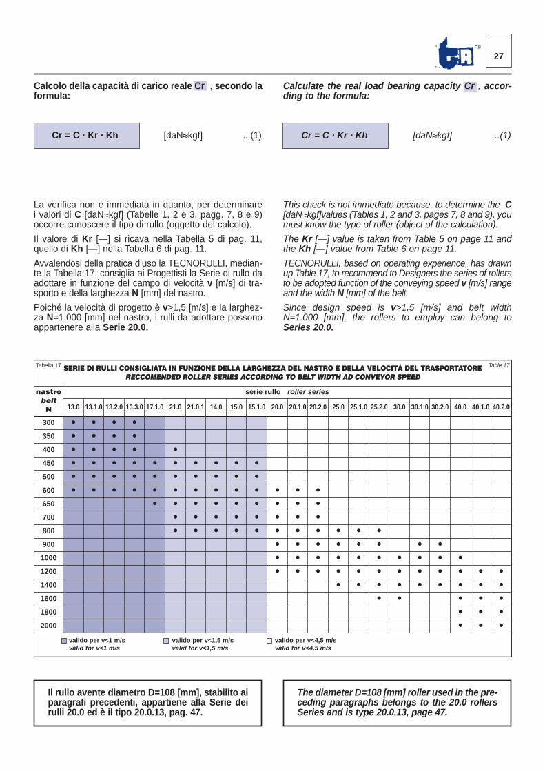
Calcolo della capacità di carico reale Cr , secondo laformula:
Cr = C · Kr · Kh [daN≈kgf] ...(1)
La verifica non è immediata in quanto, per determinarei valori di C [daN≈kgf] (Tabelle 1, 2 e 3, pagg. 7, 8 e 9)occorre conoscere il tipo di rullo (oggetto del calcolo).
Il valore di Kr [—] si ricava nella Tabella 5 di pag. 11,quel lo di Kh [—] nella Tabella 6 di pag. 11.
Avvalendosi della pratica d’uso la TECNORULLI, median -te la Tabella 17, consiglia ai Progettisti la Serie di rullo daadottare in funzione del campo di velocità v [m/s] di tra -sporto e della larghezza N [mm] del nastro.
Poiché la velocità di progetto è v>1,5 [m/s] e la larghez -za N=1.000 [mm] nel nastro, i rulli da adottare possonoappartenere alla Serie 20.0.
Calculate the real load bearing capacity Cr , accor-ding to the formula:
Cr = C · Kr · Kh [daN≈kgf] ...(1)
This check is not immediate because, to determine the C[daN≈kgf]values (Tables 1, 2 and 3, pages 7, 8 and 9), youmust know the type of roller (object of the calculation).
The Kr [—] value is taken from Table 5 on page 11 andthe Kh [—] value from Table 6 on page 11.
TECNORULLI, based on operating experience, has drawnup Table 17, to recommend to Designers the series of rollersto be adopted function of the conveying speed v [m/s] rangeand the width N [mm] of the belt.
Since design speed is v>1,5 [m/s] and belt widthN=1.000 [mm], the rollers to employ can belong toSeries 20.0.
SERIE DI RULLI CONSIGLIATA IN FUNZIONE DELLA LARGHEZZA DEL NASTRO E DELLA VELOCITÀ DEL TRASPORTATORE RECCOMENDED ROLLER SERIES ACCORDING TO BELT WIDTH AD CONVEYOR SPEED
nastrobeltN
serie rullo roller series
13.0 13.1.0 13.2.0 13.3.0 17.1.0 21.0 21.0.1 14.0 15.0 15.1.0 20.0 20.1.0 20.2.0 25.0 25.1.0 25.2.0 30.0 30.1.0 30.2.0 40.0 40.1.0 40.2.0
300 • • • •350 • • • •400 • • • • •450 • • • • • • • • • •500 • • • • • • • • • •600 • • • • • • • • • • • • •650 • • • • • • • • •700 • • • • • • • •800 • • • • • • • • • • •900 • • • • • • • •1000 • • • • • • • • • •1200 • • • • • • • • • • • •1400 • • • • • • • • •1600 • • • • •1800 • • •2000 • • •
valido per v<1 m/svalid for v<1 m/s
valido per v<1,5 m/svalid for v<1,5 m/s
valido per v<4,5 m/svalid for v<4,5 m/s
Tabella 17 Table 17
Il rullo avente diametro D=108 [mm], stabilito aiparagrafi precedenti, appartiene alla Serie deirulli 20.0 ed è il tipo 20.0.13, pag. 47.
The diameter D=108 [mm] roller used in the pre-ceding paragraphs belongs to the 20.0 rollersSeries and is type 20.0.13, page 47.
28
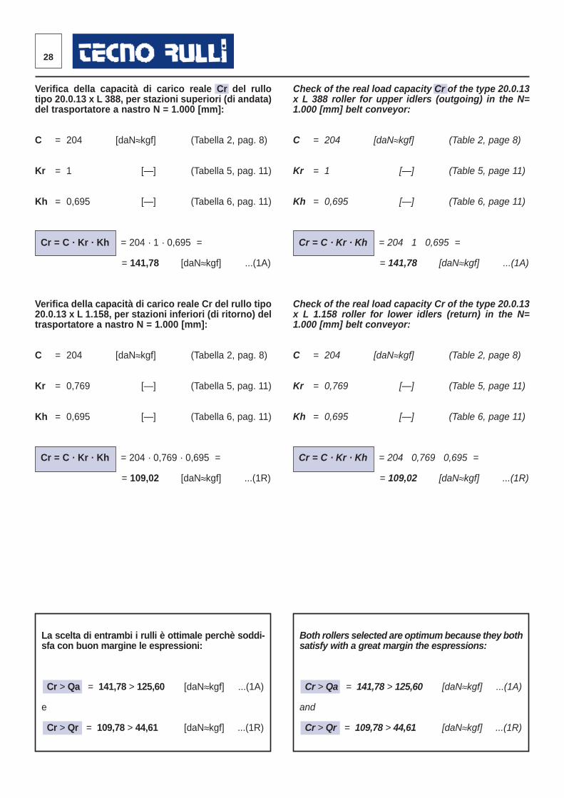
Check of the real load capacity Cr of the type 20.0.13x L 388 roller for upper idlers (outgoing) in the N=1.000 [mm] belt conveyor:
C = 204 [daN≈kgf] (Table 2, page 8)
Kr = 1 [—] (Table 5, page 11)
Kh = 0,695 [—] (Table 6, page 11)
Cr = C · Kr · Kh = 204 · 1 · 0,695 =
= 141,78 [daN≈kgf] ...(1A)
Check of the real load capacity Cr of the type 20.0.13x L 1.158 roller for lower idlers (return) in the N=1.000 [mm] belt conveyor:
C = 204 [daN≈kgf] (Table 2, page 8)
Kr = 0,769 [—] (Table 5, page 11)
Kh = 0,695 [—] (Table 6, page 11)
Cr = C · Kr · Kh = 204 · 0,769 · 0,695 =
= 109,02 [daN≈kgf] ...(1R)
Verifica della capacità di carico reale Cr del rullotipo 20.0.13 x L 388, per stazioni superiori (di andata)del trasportatore a nastro N = 1.000 [mm]:
C = 204 [daN≈kgf] (Tabella 2, pag. 8)
Kr = 1 [—] (Tabella 5, pag. 11)
Kh = 0,695 [—] (Tabella 6, pag. 11)
Cr = C · Kr · Kh = 204 · 1 · 0,695 =
= 141,78 [daN≈kgf] ...(1A)
Verifica della capacità di carico reale Cr del rullo tipo20.0.13 x L 1.158, per stazioni inferiori (di ritorno) deltrasportatore a nastro N = 1.000 [mm]:
C = 204 [daN≈kgf] (Tabella 2, pag. 8)
Kr = 0,769 [—] (Tabella 5, pag. 11)
Kh = 0,695 [—] (Tabella 6, pag. 11)
Cr = C · Kr · Kh = 204 · 0,769 · 0,695 =
= 109,02 [daN≈kgf] ...(1R)
La scelta di entrambi i rulli è ottimale perchè soddi-sfa con buon margine le espressioni:
Cr > Qa = 141,78 > 125,60 [daN≈kgf] ...(1A)
e
Cr > Qr = 109,78 > 44,61 [daN≈kgf] ...(1R)
Both rollers selected are optimum because they bothsatisfy with a great margin the espressions:
Cr > Qa = 141,78 > 125,60 [daN≈kgf] ...(1A)
and
Cr > Qr = 109,78 > 44,61 [daN≈kgf] ...(1R)
29®
LUNGHEZZE NORMALINORMAL LENGTHS
LUNGHEZZE DEI RULLI ROLLER LENGTHS
nastrobelt
rulli pianiflat idler
λ°= 0
rulli a coppie2-rollers
troughed idlersλ°= 20
rulli a terne3-rollers
troughed idlersλ°= 20, 30, 35,
40, 45
N L1 L2 L3
ISO DIN ISO DIN ISO DIN
300 388 386 208 206
350* 438* 436* 233* 231*
400 508 506 258 256 168 166
450* 558* 556* 283* 281* 188* 186*
500 608 606 323 321 208 206
600* 708* 706* 373* 371* 238* 236*
650 758 756 388 386 258 256
700* 808* 806* 416* 414* 308* 306*
800 958 956 473 471 323 321
900* 1058* 1056 538* 536 358* 356
1000 1158 1156 608 606 388 386
1200 1408 1406 708 706 473 471
1400 1608 1606 808 806 538 536
1600 1808 1806 908 906 608 606
1800 2008 2006 1008 1006 678 676
2000 2208 2206 1108 1106 758 756
2200* 2508* 2506* 1258* 1256* 808* 806*
2400* 2808* 2806* 1408* 1406* 908* 906*
* Non contemplato nelle norme ISO - DIN
* Not included in ISO - DIN norms
Tabella 18 Table 18
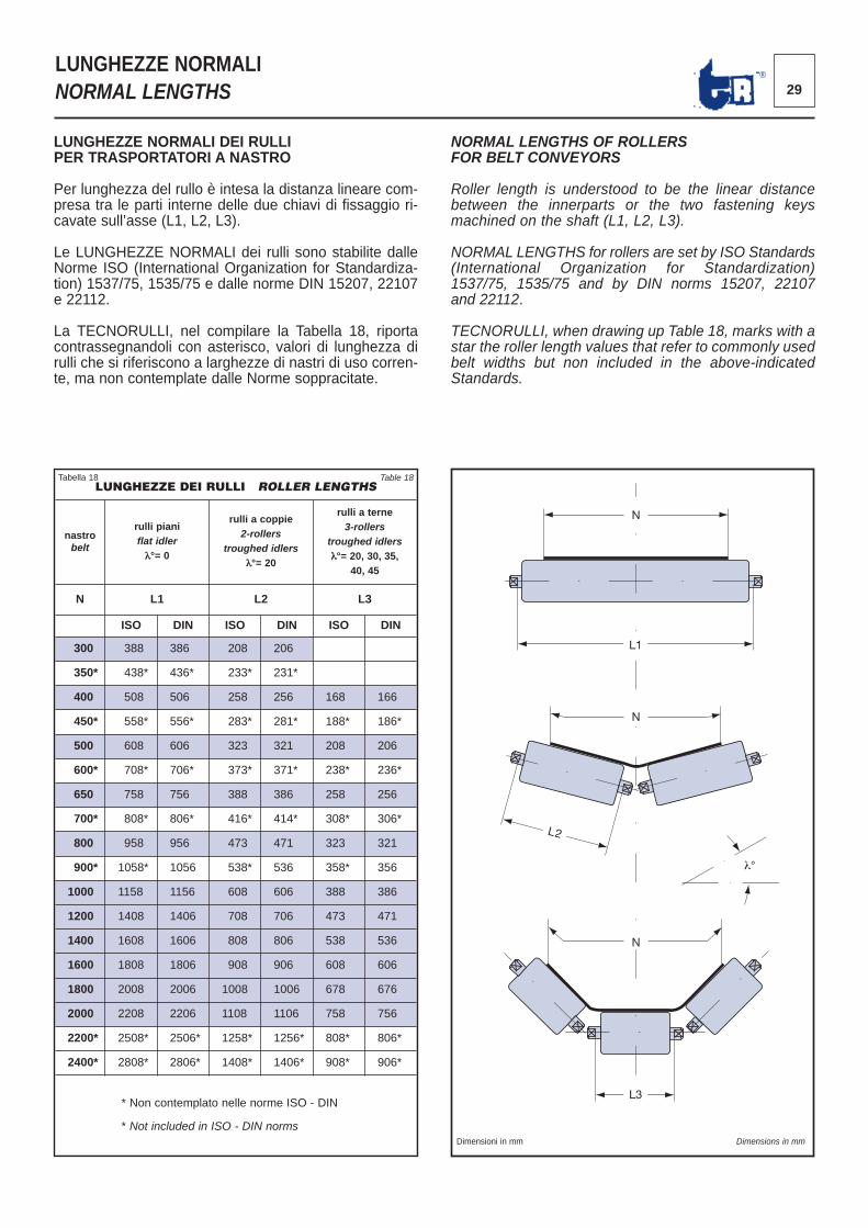
LUNGHEZZE NORMALI DEI RULLI PER TRASPORTATORI A NASTRO
Per lunghezza del rullo è intesa la distanza lineare com -presa tra le parti interne delle due chiavi di fissaggio ri -cavate sull’asse (L1, L2, L3).
Le LUNGHEZZE NORMALI dei rulli sono stabilite dalleNorme ISO (International Organization for Standardiza-tion) 1537/75, 1535/75 e dalle norme DIN 15207, 22107e 22112.
La TECNORULLI, nel compilare la Tabella 18, riportacon trassegnandoli con asterisco, valori di lunghezza dirulli che si riferiscono a larghezze di nastri di uso corren-te, ma non contemplate dalle Norme soppracitate.
NORMAL LENGTHS OF ROLLERS FOR BELT CONVEYORS
Roller length is understood to be the linear distancebetween the innerparts or the two fastening keysmachined on the shaft (L1, L2, L3).
NORMAL LENGTHS for rollers are set by ISO Standards(International Organization for Standardization)1537/75, 1535/75 and by DIN norms 15207, 22107and 22112.
TECNORULLI, when drawing up Table 18, marks with astar the roller length values that refer to commonly usedbelt widths but non included in the above-indicatedStandards.
N
N
N
L1
L3
L2
Dimensioni in mm Dimensions in mm
λ°
T
s
De D
30
FINITURA DEI RULLI E TEMPERATURA D’ESERCIZIOROLLERS’ FINISHING AND OPERATING TEMPERATURE
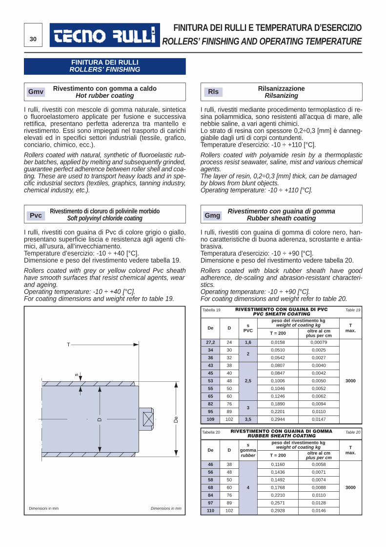
Rivestimento con gomma a caldo Hot rubber coating
I rulli, rivestiti con mescole di gomma naturale, sinteticao fluoroelastomero applicate per fusione e successivaret tifica, presentano perfetta aderenza tra mantello erive stimento. Essi sono impiegati nel trasporto di carichielevati ed in specifici settori industriali (tessile, grafico,con ciario, chimico, ecc.).
Rollers coated with natural, synthetic of fluoroelastic rub -ber batches, applied by melting and subsequently grinded,guarantee perfect adherence between roller shell and coa-ting. These are used to transport heavy loads and in spe-cific industrial sectors (textiles, graphics, tanning industry,chemical industry, etc.).
Rivestimento di cloruro di polivinile morbido Soft polyvinyl chloride coating
I rulli, rivestiti con guaina di Pvc di colore grigio o giallo,presentano superficie liscia e resistenza agli agenti chi -mici, all’usura, all’invecchiamento. Temperature d’esercizio: -10 ÷ +40 [°C]. Dimensione e peso del rivestimento vedere tabella 19.
Rollers coated with grey or yellow colored Pvc sheathhave smooth surfaces that resist chemical agents, wearand ageing.Operating temperature: -10 ÷ +40 [°C].For coating dimensions and weight refer to table 19.
Rilsanizzazione Rilsanizing
I rulli, rivestiti mediante procedimento termoplastico di re -sina poliammidica, sono resistenti all’acqua di mare, allenebbie saline, a vari agenti chimici. Lo strato di resina con spessore 0,2÷0,3 [mm] è danneg -giabile dagli urti di corpi contundenti. Temperature d’esercizio: -10 ÷ +110 [°C].
Rollers coated with polyamide resin by a thermoplasticprocess resist seawater, saline, mist and various chemicalagents.The layer of resin, 0,2÷0,3 [mm] thick, can be damagedby blows from blunt objects.Operating temperature: -10 ÷ +110 [°C].
Rivestimento con guaina di gommaRubber sheath coating
I rulli, rivestiti con guaina di gomma di colore nero, han -no caratteristiche di buona aderenza, scrostante e antia-brasiva.Temperatura d’esercizio: -10 ÷ +90 [°C]. Dimensione e peso del rivestimento vedere tabella 20.
Rollers coated with black rubber sheath have goodadherence, de-scaling and abrasion-resistant characteri-stics.Operating temperature: -10 ÷ +90 [°C].For coating dimensions and weight refer to table 20.
RIVESTIMENTO CON GUAINA DI PVCPVC SHEATH COATING
De D sPVC
peso del rivestimento kgweight of coating kg T
max.T = 200 oltre al cmplus per cm
27,2 24 1,6 0,0158 0,00079
3000
34 302
0,0510 0,0025
36 32 0,0542 0,0027
43 38
2,5
0,0807 0,0040
45 40 0,0847 0,0042
53 48 0,1006 0,0050
55 50 0,1046 0,0052
65 60 0,1246 0,0062
82 763
0,1890 0,0094
95 89 0,2201 0,0110
109 102 3,5 0,2944 0,0147
RIVESTIMENTO CON GUAINA DI GOMMARUBBER SHEATH COATING
De Ds
gommarubber
peso del rivestimento kgweight of coating kg T
max.T = 200 oltre al cmplus per cm
46 38
4
0,1160 0,0058
3000
56 48 0,1436 0,0071
58 50 0,1492 0,0074
68 60 0,1768 0,0088
84 76 0,2210 0,0110
97 89 0,2571 0,0128
110 102 0,2928 0,0146
Tabella 19 Table 19
Tabella 20 Table 20
FINITURA DEI RULLIROLLERS’ FINISHING
Gmv Rls
Pvc Gmg
Dimensioni in mm Dimensions in mm
31®
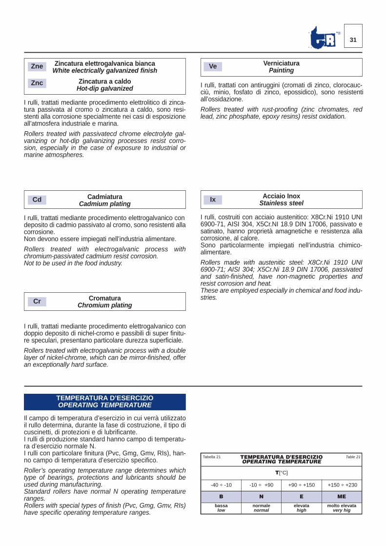
Il campo di temperatura d’esercizio in cui verrà utilizzatoil rullo determina, durante la fase di costruzione, il tipo dicuscinetti, di protezioni e di lubrificante. I rulli di produzione standard hanno campo di temperatu -ra d’esercizio normale N.I rulli con particolare finitura (Pvc, Gmg, Gmv, RIs), han -no campo di temperatura d’esercizio specifico.
Roller’s operating temperature range determines whichtype of bearings, protections and lubricants should beused during manufacturing.Standard rollers have normal N operating temperatureranges.Rollers with special types of finish (Pvc, Gmg, Gmv, RIs)have specific operating temperature ranges.
Zincatura elettrogalvanica bianca White electrically galvanized finish
Zincatura a caldoHot-dip galvanized
I rulli, trattati mediante procedimento elettrolitico di zinca-tura passivata al cromo o zincatura a caldo, sono resi-stenti alla corrosione specialmente nei casi di esposizioneall’atmosfera industriale e marina.
Rollers treated with passivatecd chrome electrolyte gal-vanizing or hot-dip galvanizing processes resist corro-sion, especially in the case of exposure to industrial ormarine atmospheres.
CadmiaturaCadmium plating
I rulli, trattati mediante procedimento elettrogalvanico condeposito di cadmio passivato al cromo, sono resistenti allacorrosione.Non devono essere impiegati nell’industria alimentare.
Rollers treated with electrogalvanic process withchromium-passivated cadmium resist corrosion. Not to be used in the food industry.
CromaturaChromium plating
I rulli, trattati mediante procedimento elettrogalvanico condoppio deposito di nichel-cromo e passibili di super finitu-re speculari, presentano particolare durezza superficiale.
Rollers treated with electrogalvanic process with a dou blelayer of nickel-chrome, which can be mirror-finished, offeran exceptionally hard surface.
VerniciaturaPainting
I rulli, trattati con antiruggini (cromati di zinco, clorocauc-ciù, minio, fosfato di zinco, epossidico), sono resisten tiall’ossidazione.
Rollers treated with rust-proofing (zinc chromates, redlead, zinc phosphate, epoxy resins) resist oxidation.
Acciaio InoxStainless steel
I rulli, costruiti con acciaio austenitico: X8Cr.Ni 1910 UNI6900-71, AISI 304, X5Cr.NI 18.9 DIN 17006, passivato esatinato, hanno proprietà amagnetiche e resistenza allacorrosione, al calore.Sono particolarmente impiegati nell’industria chimico-alimentare.
Rollers made with austenitic steel: X8Cr.Ni 1910 UNI6900-71; AISI 304; X5Cr.Ni 18.9 DIN 17006, passivatedand satin-finished, have non-magnetic properties andresist corrosion and heat.These are employed especially in chemical and food indu-stries.
TEMPERATURA D’ESERCIZIOOPERATING TEMPERATURE
T[°C]
-40 ÷ -10 -10 ÷ +90 +90 ÷ +150 +150 ÷ +230
B N E ME
bassalow
normalenormal
elevatahigh
molto elevata very hig
Tabella 21 Table 21
TEMPERATURA D’ESERCIZIOOPERATING TEMPERATURE
Zne Ve
Ix
Znc
Cd
Cr
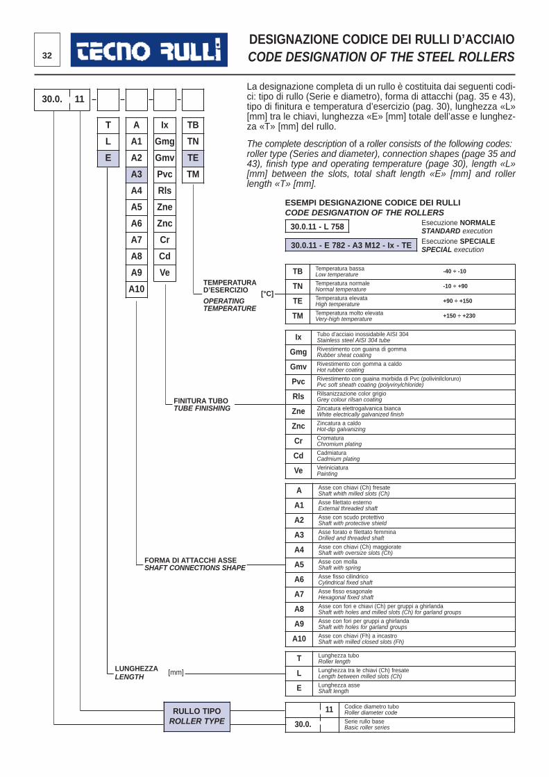
32
DESIGNAZIONE CODICE DEI RULLI D’ACCIAIO CODE DESIGNATION OF THE STEEL ROLLERS
La designazione completa di un rullo è costituita dai seguenti codi -ci: tipo di rullo (Serie e diametro), forma di attacchi (pag. 35 e 43),tipo di finitura e temperatura d’esercizio (pag. 30), lunghezza «L»[mm] tra le chiavi, lunghezza «E» [mm] totale dell’asse e lunghez-za «T» [mm] del rullo.
The complete description of a roller consists of the following codes:roller type (Series and diameter), connection shapes (page 35 and43), finish type and operating temperature (page 30), length «L»[mm] between the slots, total shaft length «E» [mm] and rollerlength «T» [mm].
TB Temperatura bassa -40 ÷ -10Low temperature
TN Temperatura normale -10 ÷ +90Normal temperature
TE Temperatura elevata +90 ÷ +150High temperature
TM Temperatura molto elevata +150 ÷ +230Very-high temperature
Ix Tubo d’acciaio inossidabile AISI 304Stainless steel AISI 304 tube
Gmg Rivestimento con guaina di gommaRubber sheat coating
Gmv Rivestimento con gomma a caldoHot rubber coating
Pvc Rivestimento con guaina morbida di Pvc (polivinilcloruro)Pvc soft sheath coating (polyvinylchloride)
Rls Rilsanizzazione color grigioGrey colour rilsan coating
Zne Zincatura elettrogalvanica biancaWhite electrically galvanized finish
Znc Zincatura a caldoHot-dip galvanizing
Cr CromaturaChromium plating
Cd CadmiaturaCadmium plating
Ve VeriniciaturaPainting
A Asse con chiavi (Ch) fresateShaft whith milled slots (Ch)
A1 Asse filettato esternoExternal threaded shaft
A2 Asse con scudo protettivoShaft with protective shield
A3 Asse forato e filettato femminaDrilled and threaded shaft
A4 Asse con chiavi (Ch) maggiorateShaft with oversize slots (Ch)
A5 Asse con mollaShaft with spring
A6 Asse fisso cilindricoCylindrical fixed shaft
A7 Asse fisso esagonaleHexagonal fixed shaft
A8 Asse con fori e chiavi (Ch) per gruppi a ghirlandaShaft with holes and milled slots (Ch) for garland groups
A9 Asse con fori per gruppi a ghirlandaShaft with holes for garland groups
A10 Asse con chiavi (Fh) a incastroShaft with milled closed slots (Fh)
T Lunghezza tuboRoller length
L Lunghezza tra le chiavi (Ch) fresateLength between milled slots (Ch)
E Lunghezza asseShaft length
11 Codice diametro tuboRoller diameter code
30.0. Serie rullo baseBasic roller series
T
L
E
30.0. 11
A
A1
A2
A3
A4
A5
A6
A7
A8
A9
A10
Ix
Gmg
Gmv
Pvc
Rls
Zne
Znc
Cr
Cd
Ve
TB
TN
TE
TM
30.0.11 - L 758
30.0.11 - E 782 - A3 M12 - Ix - TE
ESEMPI DESIGNAZIONE CODICE DEI RULLICODE DESIGNATION OF THE ROLLERS
Esecuzione NORMALESTANDARD executionEsecuzione SPECIALESPECIAL execution
TEMPERATURAD’ESERCIZIO [°C]OPERATINGTEMPERATURE
FORMA DI ATTACCHI ASSESHAFT CONNECTIONS SHAPE
FINITURA TUBOTUBE FINISHING
LUNGHEZZA [mm]LENGTH
RULLO TIPOROLLER TYPE
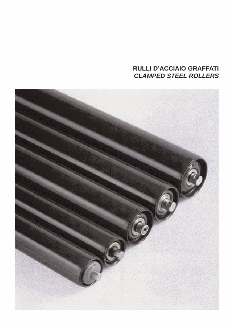
RULLI D’ACCIAIO GRAFFATICLAMPED STEEL ROLLERS
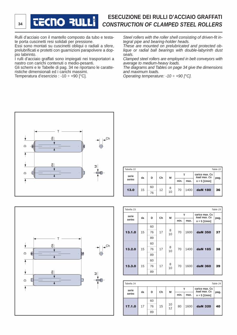
34
ESECUZIONE DEI RULLI D’ACCIAIO GRAFFATICONSTRUCTION OF CLAMPED STEEL ROLLERS
Rulli d’acciaio con il mantello composto da tubo e testa-te porta cuscinetti resi solidali per pressione. Essi sono montati su cuscinetti obliqui o radiali a sfere,prelubrificati e protetti con guarnizioni parapolvere a dop -pio labirinto.I rulli d’acciaio graffati sono impiegati nei trasportatori anastro con carichi contenuti o medio-pesanti. Gli schemi e le Tabelle di pag. 34 ne riportano le caratte -ristiche dimensionali ed i carichi massimi. Temperatura d’esercizio : -10 ÷ +90 [°C].
Steel rollers with the roller shell consisting of driven-fit in -tegral pipe and bearing-holder heads. These are mounted on prelubricated and protected ob -lique or radial ball bearings with double-labyrinth dustseals.Clamped steel rollers are employed in belt conveyors withaverage to medium-heavy loads. The diagrams and Tables on page 34 give the dimensionsand maximum loads.Operating temperature: -10 ÷ +90 [°C].
T
D
da
da
D
T
D
da
da
D
Ch
M
Ch
M
Tabella 22 Table 22
serieseries
da D Ch MT carico max. Cs
load max. Csn = 5 [1/min]
pag.min. max.
13.0 1560
12810
70 1400 daN 180 3676
Tabella 23 Table 23
serieseries
da D Ch MT carico max. Cs
load max. Csn = 5 [1/min]
pag.min. max.
13.1.0 15
60
17810
70 1600 daN 350 3776
89
13.2.0 15
60
17810
70 1400 daN 185 3876
89
13.3.0 15
60
17810
70 1600 daN 360 3976
89
Tabella 24 Table 24
serieseries
da D Ch MT carico max. Cs
load max. Csn = 5 [1/min]
pag.min. max.
17.1.0 17
60
151012
80 1600 daN 320 4076
89
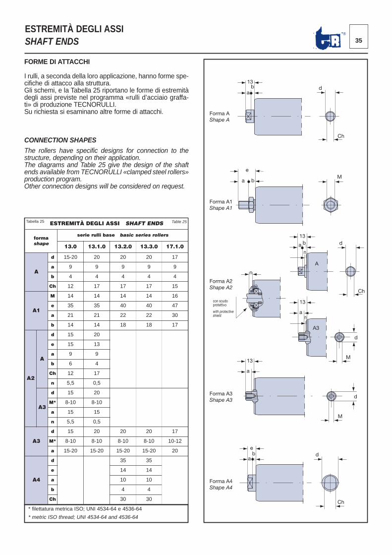
35®
ESTREMITÀ DEGLI ASSI SHAFT ENDS
FORME DI ATTACCHI
I rulli, a seconda della loro applicazione, hanno forme spe -cifiche di attacco alla struttura. Gli schemi, e la Tabella 25 riportano le forme di estremitàdegli assi previste nel programma «rulli d’acciaio graffa -ti» di produzione TECNORULLI. Su richiesta si esaminano altre forme di attacchi.
CONNECTION SHAPES
The rollers have specific designs for connection to thestructure, depending on their application.The diagrams and Table 25 give the design of the shaftends available from TECNORULLI «clamped steel rollers»production program.Other connection designs will be considered on request.
13b
Forma A Shape A
Forma A2Shape A2
Forma A3 Shape A3
Forma A4 Shape A4
con scudo protettivo with protective shield
a d
Ch
13
13
e d
Ch
a
a
a b
n
n
b
Forma A1 Shape A1
e
a b M
d
Ch
13
a n
M
d
M
d
A
A3
ESTREMITÀ DEGLI ASSI SHAFT ENDS
formashape
serie rulli base basic series rollers
13.0 13.1.0 13.2.0 13.3.0 17.1.0
A
d 15-20 20 20 20 17
a 9 9 9 9 9
b 4 4 4 4 4
Ch 12 17 17 17 15
A1
M 14 14 14 14 16
e 35 35 40 40 47
a 21 21 22 22 30
b 14 14 18 18 17
A2
A
d 15 20
e 15 13
a 9 9
b 6 4
Ch 12 17
n 5,5 0,5
A3
d 15 20
M* 8-10 8-10
a 15 15
n 5,5 0,5
A3
d 15 20 20 20 17
M* 8-10 8-10 8-10 8-10 10-12
a 15-20 15-20 15-20 15-20 20
A4
d 35 35
e 14 14
a 10 10
b 4 4
Ch 30 30
Tabella 25 Table 25
* filettatura metrica ISO; UNI 4534-64 e 4536-64
* metric ISO thread; UNI 4534-64 and 4536-64
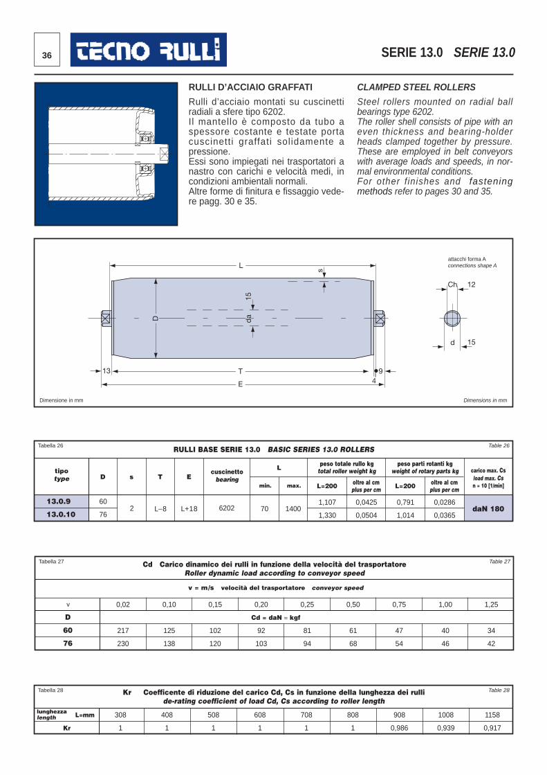
36
13
L
T
E 49
s
Ch
d
12
15
15
da D
SERIE 13.0 SERIE 13.0
RULLI D’ACCIAIO GRAFFATI
Rulli d’acciaio montati su cuscinettiradiali a sfere tipo 6202. Il mantello è composto da tubo aspes sore costante e testate portacuscinetti graffati solidamente apressione. Essi sono impiegati nei trasportatori anastro con carichi e velocità medi, incondizioni ambientali normali. Altre forme di finitura e fissaggio vede -re pagg. 30 e 35.
CLAMPED STEEL ROLLERS
Steel rollers mounted on radial ballbearings type 6202. The roller shell consists of pipe with aneven thickness and bearing-holderheads clamped together by pressure.These are employed in belt conveyorswith average loads and speeds, in nor -mal environmental conditions. For other f inishes and fasteningmethods refer to pages 30 and 35.
attacchi forma Aconnections shape A
Tabella 27 Table 27
v
v = m/s velocità del trasportatore conveyor speed
Cd Carico dinamico dei rulli in funzione della velocità del trasportatoreRoller dynamic load according to conveyor speed
D
60
76
0,02
217
230
0,10
125
138
0,15
102
120
0,20
92
103
0,25
81
94
0,50
61
68
0,75
47
54
1,00
40
46
1,25
34
42
Tabella 28 Table 28Kr Coefficente di riduzione del carico Cd, Cs in funzione della lunghezza dei rullide-rating coefficient of load Cd, Cs according to roller length
lunghezzalength
Kr
308
1
408
1
508
1
608
1
708
1
808
1
908
0,986
1008
0,939
1158
0,917
Tabella 26 Table 26
tipotype
cuscinettobearing
L
min. max. L=200 oltre al cmplus per cm L=200 oltre al cm
plus per cm
carico max. Csload max. Csn = 10 [1/min]
D s T E
RULLI BASE SERIE 13.0 BASIC SERIES 13.0 ROLLERS
13.0.9
13.0.10
60
762 L_8 L+18 6202 70 1400
1,107
1,330
0,0425
0,0504
0,791
1,014
0,0286
0,0365daN 180
L=mm
peso totale rullo kgtotal roller weight kg
peso parti rotanti kgweight of rotary parts kg
Dimensione in mm Dimensions in mm
Cd = daN ≈ kgf
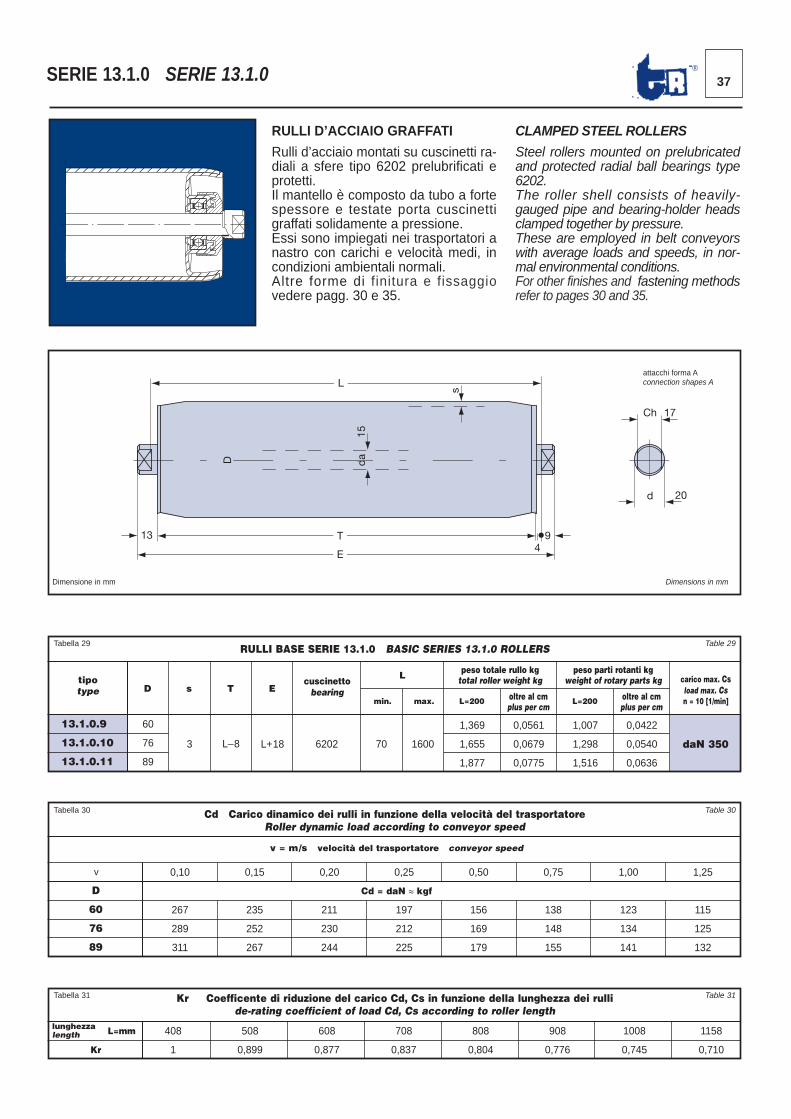
13
L
D
da
15
T
E 4
9
s
Ch 17
d 20
37®
RULLI D’ACCIAIO GRAFFATI
Rulli d’acciaio montati su cuscinetti ra -diali a sfere tipo 6202 prelubrificati eprotetti.Il mantello è composto da tubo a fortespessore e testate porta cuscinettigraf fati solidamente a pressione. Essi sono impiegati nei trasportatori anastro con carichi e velocità medi, incondizioni ambientali normali. Altre forme di finitura e fissaggiovede re pagg. 30 e 35.
CLAMPED STEEL ROLLERS
Steel rollers mounted on prelubricatedand protected radial ball bearings type6202.The roller shell consists of heavily-gauged pipe and bearing-holder headsclamped together by pressure. These are employed in belt conveyorswith average loads and speeds, in nor -mal environmental conditions. For other finishes and fastening methodsrefer to pages 30 and 35.
SERIE 13.1.0 SERIE 13.1.0
Dimensione in mm Dimensions in mm
Tabella 30 Table 30
v
v = m/s velocità del trasportatore conveyor speed
Cd = daN ≈ kgf
Cd Carico dinamico dei rulli in funzione della velocità del trasportatoreRoller dynamic load according to conveyor speed
D
60
76
89
0,10
267
289
311
0,15
235
252
267
0,20
211
230
244
0,25
197
212
225
0,50
156
169
179
0,75
138
148
155
1,00
123
134
141
1,25
115
125
132
Tabella 31 Table 31Kr Coefficente di riduzione del carico Cd, Cs in funzione della lunghezza dei rullide-rating coefficient of load Cd, Cs according to roller length
lunghezzalength
Kr
408
1
508
0,899
608
0,877
708
0,837
808
0,804
908
0,776
1008
0,745
1158
0,710
Tabella 29 Table 29
tipotype
cuscinettobearing
L
min. max. L=200 oltre al cmplus per cm
L=200 oltre al cmplus per cm
carico max. Csload max. Csn = 10 [1/min]
D s T E
RULLI BASE SERIE 13.1.0 BASIC SERIES 13.1.0 ROLLERS
13.1.0.9
13.1.0.10
13.1.0.11
60
76
89
3 L_8 L+18 6202 70 1600
1,369
1,655
1,877
0,0561
0,0679
0,0775
1,007
1,298
1,516
0,0422
0,0540
0,0636
daN 350
L=mm
peso totale rullo kgtotal roller weight kg
peso parti rotanti kgweight of rotary parts kg
attacchi forma Aconnection shapes A
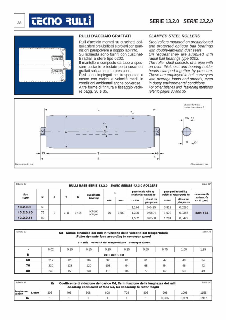
38 SERIE 13.2.0 SERIE 13.2.0
RULLI D’ACCIAIO GRAFFATI
Rulli d’acciaio montati su cuscinetti obli -qui a sfere prelubrificati e protetti con guar-nizioni parapolvere a doppio labirinto.Su richiesta sono forniti con cuscinet-ti ra diali a sfere tipo 6202. Il mantello è composto da tubo a spes -sore costante e testate porta cuscinettigraffati solidamente a pressione.Essi sono impiegati nei trasportatori anastro con carichi e velocità medi, incondizioni ambientali anche polverose. Altre forme di finitura e fissaggio vede -re pagg. 30 e 35.
CLAMPED STEEL ROLLERS
Steel rollers mounted on prelubricatedand protected oblique ball bearingswith double-labyrinth dust seals.On request they are supplied withradial ball bearings type 6202.The roller shell consists of a pipe withan even thickness and bearing-holderheads clamped together by pressure.These are employed in belt conveyorswith average loads and speeds, evenin dusty environmental conditions. For other finishes and fastening methodsrefer to pages 30 and 35.
Dimensione in mm Dimensions in mm
13
L
D
da
15
T
E 4
9
s
Ch 17
d 20
Tabella 32 Table 32
tipotype
cuscinettobearing
L
min. max. L=200 oltre al cmplus per cm
L=200 oltre al cmplus per cm
carico max. Csload max. Csn = 10 [1/min]
D s T E
RULLI BASE SERIE 13.2.0 BASIC SERIES 13.2.0 ROLLERS
13.2.0.9
13.2.0.10
13.2.0.11
60
76
89
2 L_8 L+18 obliquooblique 70 1400
1,174
1,390
1,562
0,0425
0,0504
0,0568
0,813
1,029
1,201
0,0286
0,0365
0,0429
daN 185
Tabella 33 Table 33
v
v = m/s velocità del trasportatore conveyor speed
Cd = daN ≈ kgf
Cd Carico dinamico dei rulli in funzione della velocità del trasportatoreRoller dynamic load according to conveyor speed
D
60
76
89
0,02
217
230
242
0,10
125
138
150
0,15
102
120
131
0,20
92
103
113
0,25
81
94
102
0,50
61
68
77
0,75
47
54
62
1,00
40
46
53
1,25
34
42
49
peso totale rullo kgtotal roller weight kg
peso parti rotanti kgweight of rotary parts kg
attacchi forma Aconnections shape A
Tabella 34 Table 34Kr Coefficente di riduzione del carico Cd, Cs in funzione della lunghezza dei rullide-rating coefficient of load Cd, Cs according to roller length
lunghezzalength
Kr
308
1
408
1
508
1
608
1
708
1
808
1
908
0,986
1008
0,939
1158
0,917
L=mm
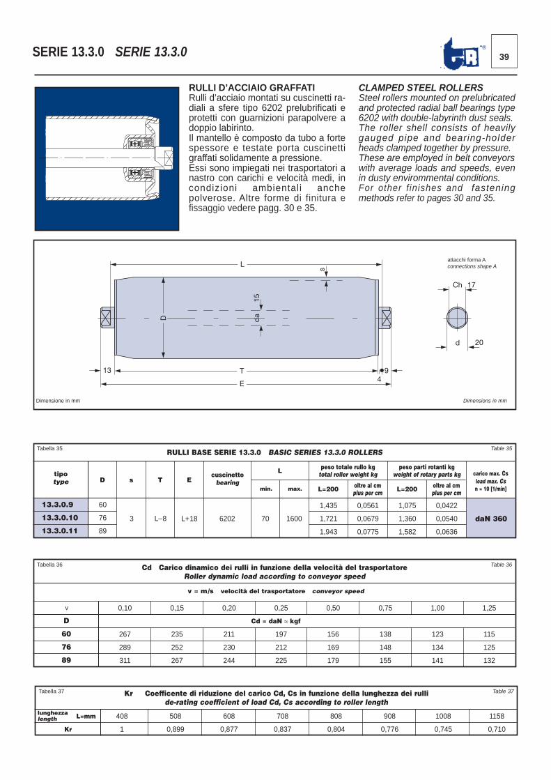
39®
RULLI D’ACCIAIO GRAFFATIRulli d’acciaio montati su cuscinetti ra -diali a sfere tipo 6202 prelubrificati eprotetti con guarnizioni parapolvere adoppio labirinto.Il mantello è composto da tubo a fortespessore e testate porta cuscinettigraf fati solidamente a pressione. Essi sono impiegati nei trasportatori anastro con carichi e velocità medi, incondizioni ambientali anchepolverose. Altre forme di finitura efissaggio vede re pagg. 30 e 35.
CLAMPED STEEL ROLLERSSteel rollers mounted on prelubricatedand protected radial ball bearings type6202 with double-labyrinth dust seals.The roller shell consists of heavilygauged pipe and bearing-holderheads clamped together by pressure.These are employed in belt conveyorswith average loads and speeds, evenin dusty envirommental conditions.For other f inishes and fasteningmethods refer to pages 30 and 35.
SERIE 13.3.0 SERIE 13.3.0
Dimensione in mm Dimensions in mm
13
L
D
da
15
T
E 4
9
s
Ch 17
d 20
Tabella 36 Table 36
v
v = m/s velocità del trasportatore conveyor speed
Cd = daN ≈ kgf
Cd Carico dinamico dei rulli in funzione della velocità del trasportatoreRoller dynamic load according to conveyor speed
D
60
76
89
0,10
267
289
311
0,15
235
252
267
0,20
211
230
244
0,25
197
212
225
0,50
156
169
179
0,75
138
148
155
1,00
123
134
141
1,25
115
125
132
Tabella 35 Table 35
tipotype
cuscinettobearing
L
min. max. L=200 oltre al cmplus per cm L=200 oltre al cm
plus per cm
carico max. Csload max. Csn = 10 [1/min]
peso totale rullo kgtotal roller weight kg
peso parti rotanti kgweight of rotary parts kg
D s T E
RULLI BASE SERIE 13.3.0 BASIC SERIES 13.3.0 ROLLERS
13.3.0.9
13.3.0.10
13.3.0.11
60
76
89
3 L_8 L+18 6202 70 1600
1,435
1,721
1,943
0,0561
0,0679
0,0775
1,075
1,360
1,582
0,0422
0,0540
0,0636
daN 360
attacchi forma Aconnections shape A
Tabella 37 Table 37Kr Coefficente di riduzione del carico Cd, Cs in funzione della lunghezza dei rullide-rating coefficient of load Cd, Cs according to roller length
lunghezzalength
Kr
408
1
508
0,899
608
0,877
708
0,837
808
0,804
908
0,776
1008
0,745
1158
0,710
L=mm
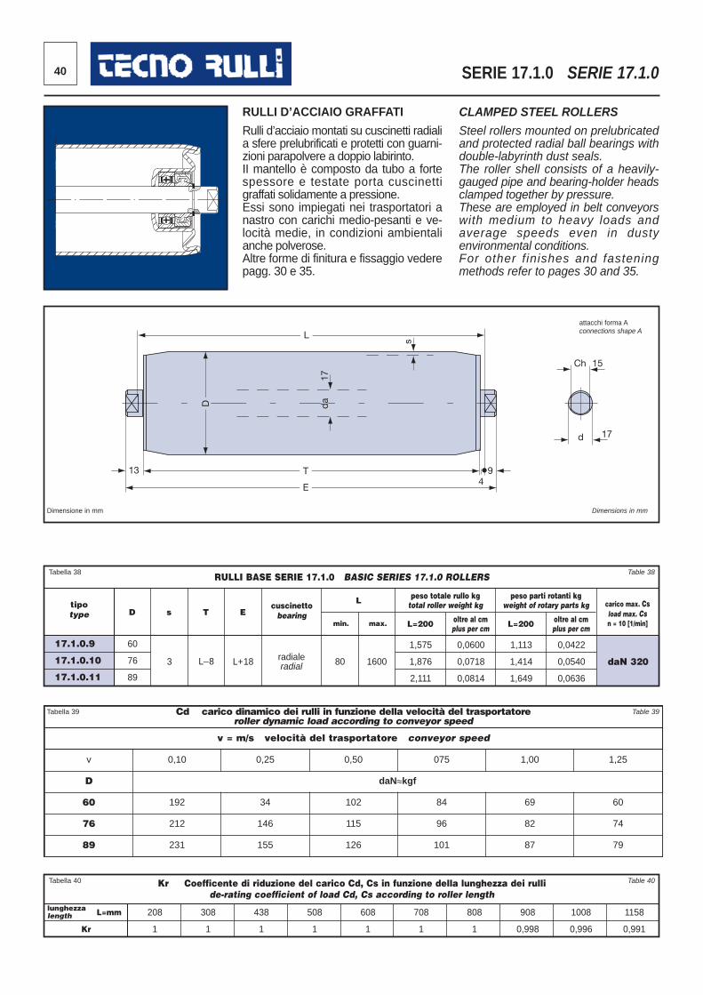
40 SERIE 17.1.0 SERIE 17.1.0
Cd carico dinamico dei rulli in funzione della velocità del trasportatore roller dynamic load according to conveyor speed
v = m/s velocità del trasportatore conveyor speed
v 0,10 0,25 0,50 075 1,00 1,25
D daN≈kgf
60 192 34 102 84 69 60
76 212 146 115 96 82 74
89 231 155 126 101 87 79
Dimensione in mm Dimensions in mm
13
L
D
da
17
T
E 4
9
s
Ch 15
d 17
RULLI D’ACCIAIO GRAFFATI
Rulli d’acciaio montati su cuscinetti radialia sfere prelubrificati e protetti con guarni -zioni parapolvere a doppio labirinto. II mantello è composto da tubo a fortespessore e testate porta cuscinettigraffati solidamente a pressione. Essi sono impiegati nei trasportatori anastro con carichi medio-pesanti e ve -locità medie, in condizioni ambientalianche polverose. Altre forme di finitura e fissaggio vederepagg. 30 e 35.
CLAMPED STEEL ROLLERS
Steel rollers mounted on prelubricatedand protected radial ball bearings withdouble-labyrinth dust seals. The roller shell consists of a heavily-gauged pipe and bearing-holder headsclamped together by pressure. These are employed in belt conveyorswith medium to heavy loads andaverage speeds even in dustyenvironmental conditions.For other f inishes and fasteningmethods refer to pages 30 and 35.
Tabella 38 Table 38
tipotype
cuscinettobearing
L
min. max. L=200 oltre al cmplus per cm L=200 oltre al cm
plus per cm
carico max. Csload max. Csn = 10 [1/min]
peso totale rullo kgtotal roller weight kg
peso parti rotanti kgweight of rotary parts kg
D s T E
RULLI BASE SERIE 17.1.0 BASIC SERIES 17.1.0 ROLLERS
17.1.0.9
17.1.0.10
17.1.0.11
60
76
89
3 L_8 L+18 radialeradial 80 1600
1,575
1,876
2,111
0,0600
0,0718
0,0814
1,113
1,414
1,649
0,0422
0,0540
0,0636
daN 320
Tabella 40 Table 40Kr Coefficente di riduzione del carico Cd, Cs in funzione della lunghezza dei rullide-rating coefficient of load Cd, Cs according to roller length
lunghezzalength
Kr
208
1
308
1
438
1
508
1
608
1
708
1
808
1
908
0,998
1008
0,996
1158
0,991
L=mm
attacchi forma Aconnections shape A
Tabella 39 Table 39
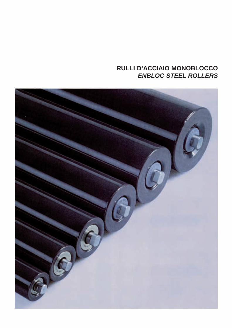
RULLI D’ACCIAIO MONOBLOCCOENBLOC STEEL ROLLERS
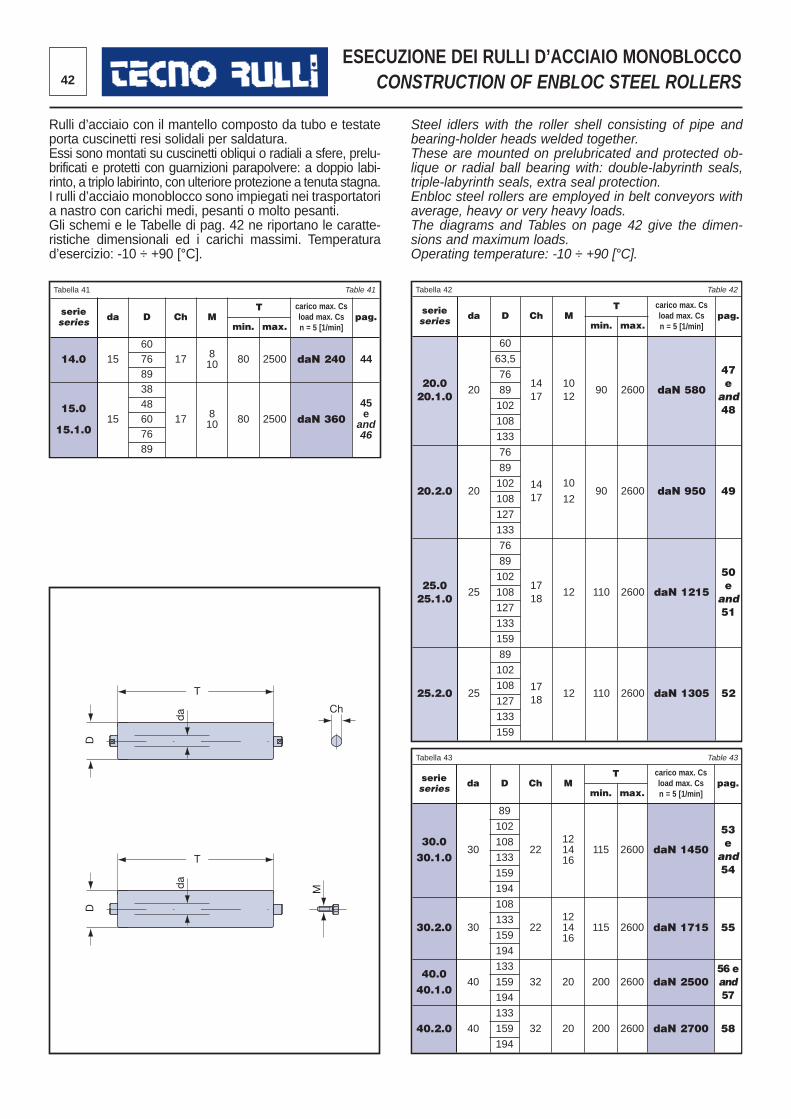
42
ESECUZIONE DEI RULLI D’ACCIAIO MONOBLOCCOCONSTRUCTION OF ENBLOC STEEL ROLLERS
Rulli d’acciaio con il mantello composto da tubo e testateporta cuscinetti resi solidali per saldatura. Essi sono montati su cuscinetti obliqui o radiali a sfere, prelu -brificati e protetti con guarnizioni parapolvere: a doppio labi -rinto, a triplo labirinto, con ulteriore protezione a tenuta stagna. I rulli d’acciaio monoblocco sono impiegati nei trasporta toria nastro con carichi medi, pesanti o molto pesanti. Gli schemi e le Tabelle di pag. 42 ne riportano le caratte -ristiche dimensionali ed i carichi massimi. Temperaturad’esercizio: -10 ÷ +90 [°C].
Steel idlers with the roller shell consisting of pipe andbearing-holder heads welded together. These are mounted on prelubricated and protected ob -lique or radial ball bearing with: double-labyrinth seals,triple-labyrinth seals, extra seal protection. Enbloc steel rollers are employed in belt conveyors withaverage, heavy or very heavy loads.The diagrams and Tables on page 42 give the dimen-sions and maximum loads. Operating temperature: -10 ÷ +90 [°C].
serieseries da D Ch M
T carico max. Csload max. Cs n = 5 [1/min]
pag.min. max.
14.0 1560
17 810 80 2500 daN 240 4476
89
15.0
15.1.015
38
17 810 80 2500 daN 360
45e
and46
48607689
serieseries da D Ch M
T carico max. Csload max. Cs n = 5 [1/min]
pag.min. max.
20.020.1.0
20
60
1417
1012
90 2600 daN 580
47eand48
63,5
76
89
102
108
133
20.2.0 20
76
1417
10
1290 2600 daN 950 49
89
102
108
127
133
25.025.1.0
25
76
1718
12 110 2600 daN 1215
50eand51
89
102
108
127
133
159
25.2.0 25
89
1718
12 110 2600 daN 1305 52
102
108
127
133
159
Tabella 41 Table 41 Tabella 42 Table 42
T
D
da
T
D
da
Ch
M
serieseries da D Ch M
T carico max. Csload max. Cs n = 5 [1/min]
pag.min. max.
30.030.1.0
30
89
22121416
115 2600 daN 1450
53eand54
102
108
133
159
194
30.2.0 30
108
22121416
115 2600 daN 1715 55133
159
194
40.040.1.0
40
133
32 20 200 2600 daN 250056 eand57
159
194
40.2.0 40
133
32 20 200 2600 daN 2700 58159
194
Tabella 43 Table 43
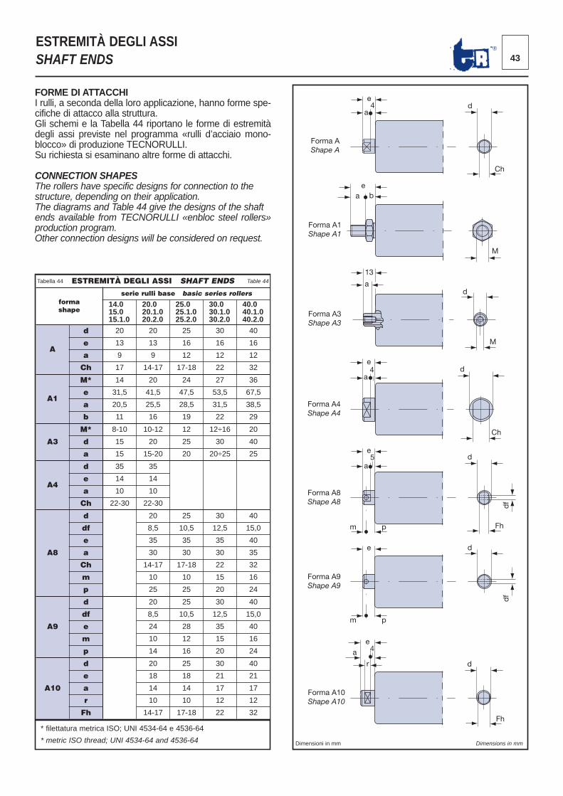
43®
ESTREMITÀ DEGLI ASSISHAFT ENDS
FORME DI ATTACCHII rulli, a seconda della loro applicazione, hanno forme spe -cifiche di attacco alla struttura. Gli schemi e la Tabella 44 riportano le forme di estremitàdegli assi previste nel programma «rulli d’acciaio mono -blocco» di produzione TECNORULLI. Su richiesta si esaminano altre forme di attacchi.
CONNECTION SHAPESThe rollers have specific designs for connection to thestructure, depending on their application.The diagrams and Table 44 give the designs of the shaftends available from TECNORULLI «enbloc steel rollers»production program.Other connection designs will be considered on request.
ESTREMITÀ DEGLI ASSI SHAFT ENDS
formashape
serie rulli base basic series rollers
14.015.015.1.0
20.020.1.020.2.0
25.025.1.025.2.0
30.030.1.030.2.0
40.040.1.040.2.0
A
d 20 20 25 30 40
e 13 13 16 16 16
a 9 9 12 12 12
Ch 17 14-17 17-18 22 32
A1
M* 14 20 24 27 36
e 31,5 41,5 47,5 53,5 67,5
a 20,5 25,5 28,5 31,5 38,5
b 11 16 19 22 29
A3
M* 8-10 10-12 12 12÷16 20
d 15 20 25 30 40
a 15 15-20 20 20÷25 25
A4
d 35 35
e 14 14
a 10 10
Ch 22-30 22-30
A8
d 20 25 30 40
df 8,5 10,5 12,5 15,0
e 35 35 35 40
a 30 30 30 35
Ch 14-17 17-18 22 32
m 10 10 15 16
p 25 25 20 24
A9
d 20 25 30 40
df 8,5 10,5 12,5 15,0
e 24 28 35 40
m 10 12 15 16
p 14 16 20 24
A10
d 20 25 30 40
e 18 18 21 21
a 14 14 17 17
r 10 10 12 12
Fh 14-17 17-18 22 32
Tabella 44 Table 44
Forma AShape A
e4
a d
Ch
Forma A1Shape A1
ea b
M
13
a
M
d
Forma A3Shape A3
e
a 4
Forma A4Shape A4
d
Ch
Forma A8Shape A8
e
m p
5 a
d
df
Fh
e
m p
d
df
Forma A9Shape A9
Forma A10Shape A10
ea 4
d
Fh
r
* filettatura metrica ISO; UNI 4534-64 e 4536-64
* metric ISO thread; UNI 4534-64 and 4536-64 Dimensioni in mm Dimensions in mm
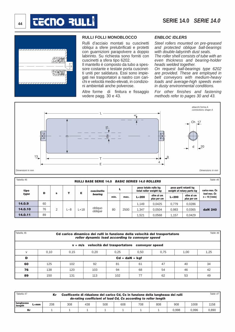
44SERIE 14.0 SERIE 14.0
Cd carico dinamico dei rulli in funzione della velocità del trasportatoreroller dynamic load ac cording to conveyor speed
v = m/s velocità del trasportatore conveyor speed
v 0,10 0,15 0,20 0,25 0,50 0,75 1,00 1,25
D Cd = daN = kgf
60 125 102 92 81 61 47 40 34
76 138 120 103 94 68 54 46 42
89 150 131 113 102 77 62 53 49
Tabella 46 Table 46
13
L
D
15
T
E 4
9
s
Ch 17
d 20
da
Tabella 45 Table 45
tipotype
cuscinettobearing
L
min. max. L=200 oltre al cmplus per cm L=200 oltre al cm
plus per cm
carico max. Csload max. Csn = 10 [1/min]
peso totale rullo kgtotal roller weight kg
peso parti rotanti kgweight of rotary parts kg
D s T E
RULLI BASE SERIE 14.0 BASIC SERIES 14.0 ROLLERS
14.0.9
14.0.10
14.0.11
60
76
89
2 L_8 L+18 obliquooblique 80 2500
1,149
1,347
1,521
0,0425
0,0504
0,0568
0,779
0,983
1,157
0,0286
0,0365
0,0429
daN 240
Tabella 47 Table 47Kr Coefficente di riduzione del carico Cd, Cs in funzione della lunghezza dei rullide-rating coefficient of load Cd, Cs according to roller length
lunghezzalength
Kr
208
1
308
1
438
1
508
1
608
1
708
1
808
1
908
0,998
1008
0,996
1158
0,890
L=mm
Dimensioni in mm Dimensions in mm
attacchi forma Aconnections shape A
RULLI FOLLI MONOBLOCCORulli d’acciaio montati su cuscinettiobliqui a sfere prelubrificati e protetticon guarnizioni parapolvere a doppiolabirinto. Su richiesta sono forniti concuscinetti a sfera tipo 6202.Il mantello è composto da tubo a spes-sore costante e testate porta cuscinet-ti uniti per saldatura. Essi sono impie-gati nei trasportatori a nastro con cari-chi e velocità medio-elevati, in condizio-ni ambientali anche polverose.Altre forme di finitura e fissaggiovedere pagg. 30 e 43.
ENBLOC IDLERSSteel rollers mounted on pre-greasedand protected oblique ball-bearingswith double-labyrinth dust seals.The roller shell consists of tube with aneven thickness and bearing-holderheads welded together. On request ball-bearings type 6202are provided. These are employed inbelt conveyors with medium-heavyloads and average-high speeds evenin dusty environmental conditions.For other finishes and fasteningmethods refer to pages 30 and 43.
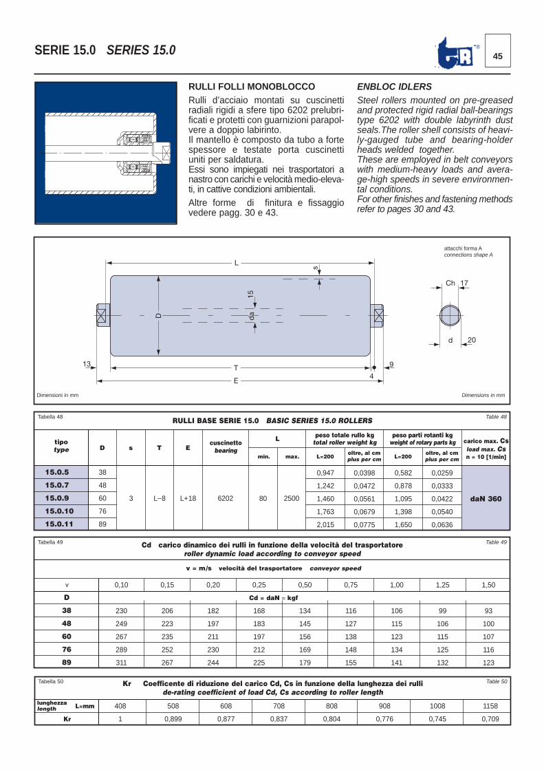
45®SERIE 15.0 SERIES 15.0
RULLI FOLLI MONOBLOCCORulli d’acciaio montati su cuscinettiradiali rigidi a sfere tipo 6202 prelubri-ficati e protetti con guarnizioni parapol-vere a doppio labirinto. Il mantello è composto da tubo a fortespessore e testate porta cuscinettiuniti per saldatura. Essi sono impiegati nei trasportatori anastro con carichi e velocità medio-eleva-ti, in cattive condizioni ambientali.Altre forme di finitura e fissaggiovedere pagg. 30 e 43.
ENBLOC IDLERSSteel rollers mounted on pre-greasedand protected rigid radial ball-bearingstype 6202 with double labyrinth dustseals.The roller shell consists of heavi-ly-gauged tube and bearing-holderheads welded together.These are employed in belt conveyorswith medium-heavy loads and avera-ge-high speeds in severe environmen-tal conditions.For other finishes and fastening methodsrefer to pages 30 and 43.
Tabella 49 Table 49
v
v = m/s velocità del trasportatore conveyor speed
Cd = daN ≈ kgf
Cd carico dinamico dei rulli in funzione della velocità del trasportatoreroller dynamic load according to conveyor speed
D
38
48
60
76
89
0,10
230
249
267
289
311
0,15
206
223
235
252
267
0,20
182
197
211
230
244
0,25
168
183
197
212
225
0,50
134
145
156
169
179
0,75
116
127
138
148
155
1,00
106
115
123
134
141
1,25
99
106
115
125
132
1,50
93
100
107
116
123
Tabella 48 Table 48
tipotype
cuscinettobearing
L
min. max. L=200oltre, al cmplus per cm L=200
oltre, al cmplus per cm
carico max. Csload max. Csn = 10 [1/min]
peso totale rullo kgtotal roller weight kg
peso parti rotanti kgweight of rotary parts kg
D s T E
RULLI BASE SERIE 15.0 BASIC SERIES 15.0 ROLLERS
15.0.5
15.0.7
15.0.9
15.0.10
15.0.11
38
48
60
76
89
3 L_8 L+18 6202 80 2500
0,947
1,242
1,460
1,763
2,015
0,0398
0,0472
0,0561
0,0679
0,0775
0,582
0,878
1,095
1,398
1,650
0,0259
0,0333
0,0422
0,0540
0,0636
daN 360
13
L
D
15
T
E 4
9
s
Ch 17
d 20
da
Dimensioni in mm Dimensions in mm
attacchi forma Aconnections shape A
Tabella 50 Table 50Kr Coefficente di riduzione del carico Cd, Cs in funzione della lunghezza dei rullide-rating coefficient of load Cd, Cs according to roller length
lunghezzalength
Kr
408
1
508
0,899
608
0,877
708
0,837
808
0,804
908
0,776
1008
0,745
1158
0,709
L=mm
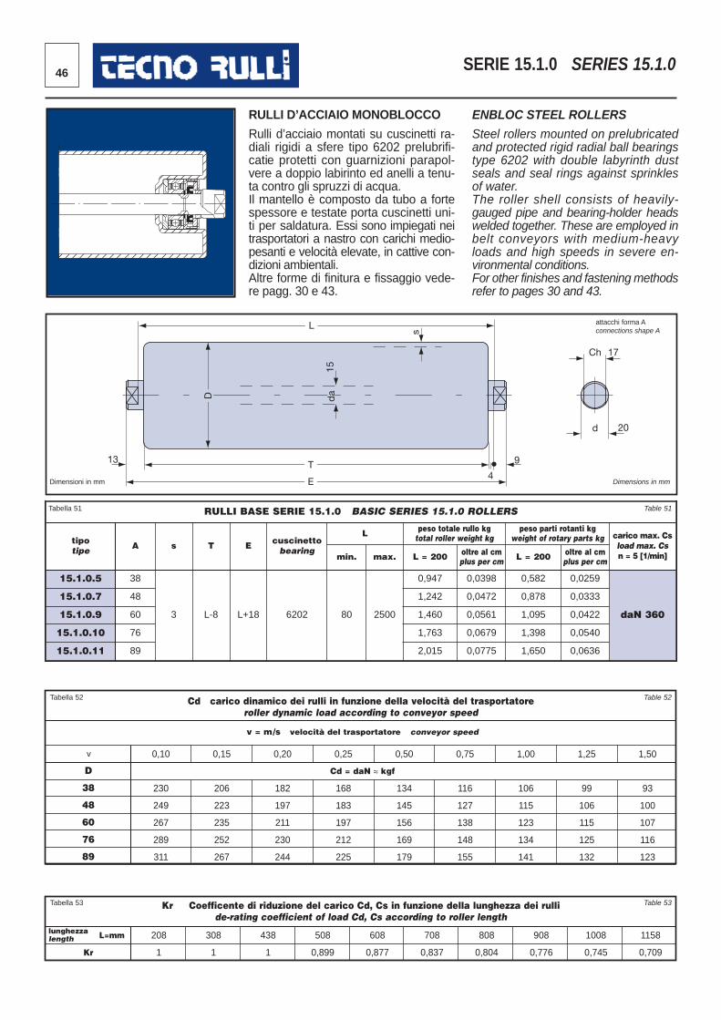
46 SERIE 15.1.0 SERIES 15.1.0
Tabella 52 Table 52
v
v = m/s velocità del trasportatore conveyor speed
Cd = daN ≈ kgf
Cd carico dinamico dei rulli in funzione della velocità del trasportatoreroller dynamic load according to conveyor speed
D
38
48
60
76
89
0,10
230
249
267
289
311
0,15
206
223
235
252
267
0,20
182
197
211
230
244
0,25
168
183
197
212
225
0,50
134
145
156
169
179
0,75
116
127
138
148
155
1,00
106
115
123
134
141
1,25
99
106
115
125
132
1,50
93
100
107
116
123
13
L
D
15
T
E 4
9
s
Ch 17
d 20
da
Dimensioni in mm Dimensions in mm
RULLI D’ACCIAIO MONOBLOCCO
Rulli d’acciaio montati su cuscinetti ra -diali rigidi a sfere tipo 6202 prelubrifi -catie protetti con guarnizioni parapol-vere a doppio labirinto ed anelli a tenu -ta contro gli spruzzi di acqua. Il mantello è composto da tubo a fortespessore e testate porta cuscinetti uni -ti per saldatura. Essi sono impiegati neitrasportatori a nastro con carichi medio -pesanti e velocità elevate, in cattive con -dizioni ambientali.Altre forme di finitura e fissaggio vede -re pagg. 30 e 43.
ENBLOC STEEL ROLLERS
Steel rollers mounted on prelubricatedand protected rigid radial ball bearingstype 6202 with double labyrinth dustseals and seal rings against sprinklesof water.The roller shell consists of heavily-gauged pipe and bearing-holder headswelded together. These are employed inbelt conveyors with medium-heavyloads and high speeds in severe en-vironmental conditions. For other finishes and fastening methodsrefer to pages 30 and 43.
RULLI BASE SERIE 15.1.0 BASIC SERIES 15.1.0 ROLLERS
tipotipe A s T E cuscinetto
bearing
L peso totale rullo kgtotal roller weight kg
peso parti rotanti kgweight of rotary parts kg carico max. Cs
load max. Csn = 5 [1/min]min. max. L = 200 oltre al cm
plus per cm L = 200 oltre al cmplus per cm
15.1.0.5 38
3 L-8 L+18 6202 80 2500
0,947 0,0398 0,582 0,0259
daN 360
15.1.0.7 48 1,242 0,0472 0,878 0,0333
15.1.0.9 60 1,460 0,0561 1,095 0,0422
15.1.0.10 76 1,763 0,0679 1,398 0,0540
15.1.0.11 89 2,015 0,0775 1,650 0,0636
Tabella 51 Table 51
Tabella 53 Table 53Kr Coefficente di riduzione del carico Cd, Cs in funzione della lunghezza dei rullide-rating coefficient of load Cd, Cs according to roller length
lunghezzalength
Kr
208
1
308
1
438
1
508
0,899
608
0,877
708
0,837
808
0,804
908
0,776
1008
0,745
1158
0,709
L=mm
attacchi forma Aconnections shape A
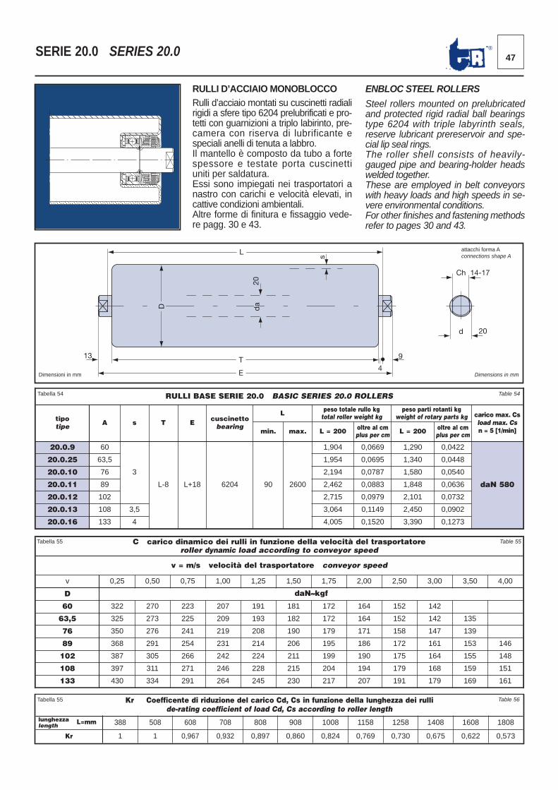
47®SERIE 20.0 SERIES 20.0
C carico dinamico dei rulli in funzione della velocità del trasportatore roller dynamic load according to conveyor speed
v = m/s velocità del trasportatore conveyor speed
v 0,25 0,50 0,75 1,00 1,25 1,50 1,75 2,00 2,50 3,00 3,50 4,00
D daN≈kgf
60 322 270 223 207 191 181 172 164 152 142
63,5 325 273 225 209 193 182 172 164 152 142 135
76 350 276 241 219 208 190 179 171 158 147 139
89 368 291 254 231 214 206 195 186 172 161 153 146
102 387 305 266 242 224 211 199 190 175 164 155 148
108 397 311 271 246 228 215 204 194 179 168 159 151
133 430 334 291 264 245 230 217 207 191 179 169 161
Tabella 55 Table 55
13
L
D
20
T
E 4
9
s
Ch 14-17
d 20
da
Dimensioni in mm Dimensions in mm
RULLI D’ACCIAIO MONOBLOCCORulli d’acciaio montati su cuscinetti radialirigidi a sfere tipo 6204 prelubrificati e pro- tetti con guarnizioni a triplo labirinto, pre -camera con riserva di lubrificante especiali anelli di tenuta a labbro. Il mantello è composto da tubo a fortespessore e testate porta cuscinettiuni ti per saldatura.Essi sono impiegati nei trasportatori anastro con carichi e velocità elevati, incattive condizioni ambientali. Altre forme di finitura e fissaggio vede -re pagg. 30 e 43.
ENBLOC STEEL ROLLERS
Steel rollers mounted on prelubricatedand protected rigid radial ball bearingstype 6204 with triple labyrinth seals,reserve lubricant prereservoir and spe -cial lip seal rings.The roller shell consists of heavily-gauged pipe and bearing-holder headswelded together.These are employed in belt conveyorswith heavy loads and high speeds in se -vere environmental conditions. For other finishes and fastening methodsrefer to pages 30 and 43.
RULLI BASE SERIE 20.0 BASIC SERIES 20.0 ROLLERS
tipotipe A s T E cuscinetto
bearing
L peso totale rullo kgtotal roller weight kg
peso parti rotanti kgweight of rotary parts kg carico max. Cs
load max. Csn = 5 [1/min]min. max. L = 200 oltre al cm
plus per cm L = 200 oltre al cmplus per cm
20.0.9 60
3
L-8 L+18 6204 90 2600
1,904 0,0669 1,290 0,0422
daN 580
20.0.25 63,5 1,954 0,0695 1,340 0,0448
20.0.10 76 2,194 0,0787 1,580 0,0540
20.0.11 89 2,462 0,0883 1,848 0,0636
20.0.12 102 2,715 0,0979 2,101 0,0732
20.0.13 108 3,5 3,064 0,1149 2,450 0,0902
20.0.16 133 4 4,005 0,1520 3,390 0,1273
Tabella 54 Table 54
Kr Coefficente di riduzione del carico Cd, Cs in funzione della lunghezza dei rullide-rating coefficient of load Cd, Cs according to roller length
lunghezzalength 388 508 608 708 808 908 1008 1158 1258 1408 1608 1808
Kr 1 1 0,967 0,932 0,897 0,860 0,824 0,769 0,730 0,675 0,622 0,573
L=mm
Tabella 55 Table 56
attacchi forma Aconnections shape A
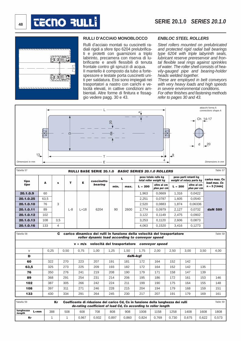
48 SERIE 20.1.0 SERIES 20.1.0
C carico dinamico dei rulli in funzione della velocità del trasportatore roller dynamic load according to conveyor speed
v = m/s velocità del trasportatore conveyor speed
v 0,25 0,50 0,75 1,00 1,25 1,50 1,75 2,00 2,50 3,00 3,50 4,00
D daN≈kgf
60 322 270 223 207 191 181 172 164 152 142
63,5 325 273 225 209 193 182 172 164 152 142 135
76 350 276 241 219 208 190 179 171 158 147 139
89 368 291 254 231 214 206 195 186 172 161 153 146
102 387 305 266 242 224 211 199 190 175 164 155 148
108 397 311 271 246 228 215 204 194 179 168 159 151
133 430 334 291 264 245 230 217 207 191 179 169 161
RULLI BASE SERIE 20.1.0 BASIC SERIES 20.1.0 ROLLERS
tipotipe A s T E cuscinetto
bearing
L peso totale rullo kgtotal roller weight kg
peso parti rotanti kgweight of rotary parts kg carico max. Cs
load max. Csn = 5 [1/min]min. max. L = 200 oltre al cm
plus per cm L = 200 oltre al cmplus per cm
20.1.0.9 60
3
L-8 L+18 6204 90 2600
1,963 0,0669 1,316 0,0422
daN 580
20.1.0.25 63,5 2,251 0,0787 1,605 0,0540
20.1.0.10 76 2,520 0,0883 1,874 0,06336
20.1.0.11 89 2,774 0,0979 2,127 0,0732
20.1.0.12 102 3,122 0,1149 2,475 0,0902
20.1.0.13 108 3,5 3,253 0,1120 2,606 0,0873
20.1.0.16 133 4 4,063 0,1520 3,416 0,1273
Tabella 57 Table 57
Tabella 58 Table 58
13
L
D
20
T
E 4
9
s
Ch 14-17
d 20
da
Dimensioni in mm Dimensions in mm
RULLI D’ACCIAIO MONOBLOCCO
Rulli d’acciaio montati su cuscinetti ra-diali rigidi a sfere tipo 6204 prelubrifica-ti e protetti con guarnizioni a triplolabirinto, precamera con riserva di lu-brificante e anelli flessibili di tenutafrontale contro gli spruzzi di acqua.II mantello è composto da tubo a forte-spessore e testate porta cuscinetti uni-ti per saldatura. Essi sono impiegati neitrasportatori a nastro con carichi e ve-locità elevati, in cattive condizioni am-bientali. Altre forme di finitura e fissag-gio vede re pagg. 30 e 43.
ENBLOC STEEL ROLLERS
Steel rollers mounted on prelubricatedand protected rigid radial ball bearingstype 6204 with triple labyrinth seals,lubricant reserve prereservoir and fron-tal flexible seal rings against sprinklesof water. The roller shell consists of hea-vily-gauged pipe and bearing-holderheads welded together. These are employed in belt conveyorswith very heavy loads and high speedsin severe environmental conditions.For other finishes and fastening methodsrefer to pages 30 and 43.
Kr Coefficente di riduzione del carico Cd, Cs in funzione della lunghezza dei rullide-rating coefficient of load Cd, Cs according to roller length
lunghezzalength 388 508 608 708 808 908 1008 1158 1258 1408 1608 1808
Kr 1 1 0,967 0,932 0,897 0,860 0,824 0,769 0,730 0,675 0,622 0,573
L=mm
Tabella 59 Table 59
attacchi forma Aconnections shape A
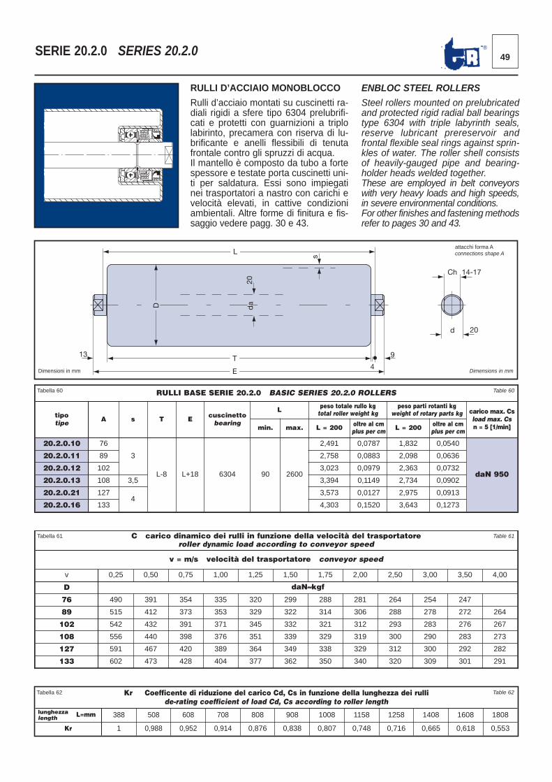
49®SERIE 20.2.0 SERIES 20.2.0
C carico dinamico dei rulli in funzione della velocità del trasportatore roller dynamic load according to conveyor speed
v = m/s velocità del trasportatore conveyor speed
v 0,25 0,50 0,75 1,00 1,25 1,50 1,75 2,00 2,50 3,00 3,50 4,00
D daN≈kgf
76 490 391 354 335 320 299 288 281 264 254 247
89 515 412 373 353 329 322 314 306 288 278 272 264
102 542 432 391 371 345 332 321 312 293 283 276 267
108 556 440 398 376 351 339 329 319 300 290 283 273
127 591 467 420 389 364 349 338 329 312 300 292 282
133 602 473 428 404 377 362 350 340 320 309 301 291
Tabella 61 Table 61
13
L
D
20
T
E 4
9
s
Ch 14-17
d 20
da
Dimensioni in mm Dimensions in mm
RULLI D’ACCIAIO MONOBLOCCO
Rulli d’acciaio montati su cuscinetti ra -diali rigidi a sfere tipo 6304 prelubrifi -cati e protetti con guarnizioni a triplolabirinto, precamera con riserva di lu -brificante e anelli flessibili di tenutafrontale contro gli spruzzi di acqua. Il mantello è composto da tubo a fortespessore e testate porta cuscinetti uni -ti per saldatura. Essi sono impiegatinei trasportatori a nastro con carichi eve locità elevati, in cattive condizioniam bientali. Altre forme di finitura e fis-saggio vede re pagg. 30 e 43.
ENBLOC STEEL ROLLERS
Steel rollers mounted on prelubricatedand protected rigid radial ball bearingstype 6304 with triple labyrinth seals,reserve lubricant prereservoir andfron tal flexible seal rings against sprin-kles of water. The roller shell consistsof heavily-gauged pipe and bearing-holder heads welded together. These are employed in belt conveyorswith very heavy loads and high speeds,in severe environmental conditions. For other finishes and fastening methodsrefer to pages 30 and 43.
Kr Coefficente di riduzione del carico Cd, Cs in funzione della lunghezza dei rullide-rating coefficient of load Cd, Cs according to roller length
lunghezzalength 388 508 608 708 808 908 1008 1158 1258 1408 1608 1808
Kr 1 0,988 0,952 0,914 0,876 0,838 0,807 0,748 0,716 0,665 0,618 0,553
Tabella 62 Table 62
RULLI BASE SERIE 20.2.0 BASIC SERIES 20.2.0 ROLLERS
tipotipe A s T E cuscinetto
bearing
L peso totale rullo kgtotal roller weight kg
peso parti rotanti kgweight of rotary parts kg carico max. Cs
load max. Csn = 5 [1/min]min. max. L = 200 oltre al cm
plus per cm L = 200 oltre al cmplus per cm
20.2.0.10 76
3
L-8 L+18 6304 90 2600
2,491 0,0787 1,832 0,0540
daN 950
20.2.0.11 89 2,758 0,0883 2,098 0,0636
20.2.0.12 102 3,023 0,0979 2,363 0,0732
20.2.0.13 108 3,5 3,394 0,1149 2,734 0,0902
20.2.0.21 1274
3,573 0,0127 2,975 0,0913
20.2.0.16 133 4,303 0,1520 3,643 0,1273
Tabella 60 Table 60
L=mm
attacchi forma Aconnections shape A
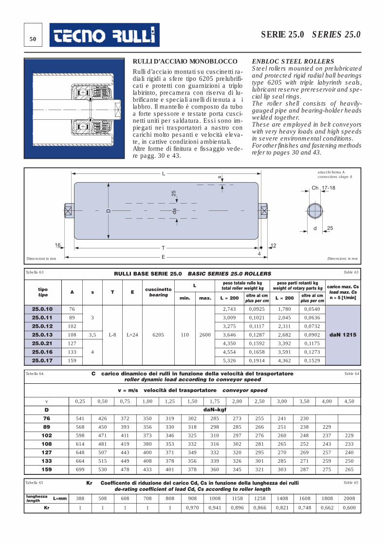
50 SERIE 25.0 SERIES 25.0
16
L
D
25
T
E 4
12
s
Ch 17-18
d 25
da
Dimensioni in mm Dimensions in mm
RULLI D’ACCIAIO MONOBLOCCO
Rulli d’acciaio montati su cuscinetti ra -diali rigidi a sfere tipo 6205 prelubrifi -cati e protetti con guarnizioni a triplolabirinto, precamera con riserva di lu -brificante e speciali anelli di tenuta a ilabbro. Il mantello è composto da tuboa forte spessore e testate porta cusci -netti uniti per saldatura. Essi sono im -piegati nei trasportatori a nastro concarichi molto pesanti e velocità eleva -te, in cattive condizioni ambientali. Altre forme di finitura e fissaggio vede -re pagg. 30 e 43.
ENBLOC STEEL ROLLERSSteel rollers mounted on prelubricatedand protected rigid radial ball bearingstype 6205 with triple labyrinth seals,lubricant reserve prereservoir and spe -cial lip seal rings.The roller shell consists of heavily-gauged pipe and bearing-holder headswelded together.These are employed in belt conveyorswith very heavy loads and high speedsin severe environmental conditions. For other finishes and fastening methodsrefer to pages 30 and 43.
C carico dinamico dei rulli in funzione della velocità del trasportatore roller dynamic load according to conveyor speed
v = m/s velocità del trasportatore conveyor speed
v 0,25 0,50 0,75 1,00 1,25 1,50 1,75 2,00 2,50 3,00 3,50 4,00 4,50
D daN≈kgf
76 541 426 372 350 319 302 285 273 255 241 230
89 568 450 393 356 330 318 298 285 266 251 238 229
102 598 471 411 373 346 325 310 297 276 260 248 237 229
108 614 481 419 380 353 332 316 302 281 265 252 243 233
127 648 507 443 400 371 349 332 320 295 270 269 257 240
133 664 515 449 408 378 356 339 326 301 285 271 259 250
159 699 530 478 433 401 378 360 345 321 303 287 275 265
RULLI BASE SERIE 25.0 BASIC SERIES 25.0 ROLLERS
tipotipe A s T E cuscinetto
bearing
L peso totale rullo kgtotal roller weight kg
peso parti rotanti kgweight of rotary parts kg carico max. Cs
load max. Csn = 5 [1/min]min. max. L = 200 oltre al cm
plus per cm L = 200 oltre al cmplus per cm
25.0.10 76
3
L-8 L+24 6205 110 2600
2,743 0,0925 1,780 0,0540
daN 1215
25.0.11 89 3,009 0,1021 2,045 0,0636
25.0.12 102 3,275 0,1117 2,311 0,0732
25.0.13 108 3,5 3,646 0,1287 2,682 0,0902
25.0.21 127
4
4,350 0,1592 3,392 0,1175
25.0.16 133 4,554 0,1658 3,591 0,1273
25.0.17 159 5,326 0,1914 4,362 0,1529
Tabella 63 Table 63
Tabella 64 Table 64
Kr Coefficente di riduzione del carico Cd, Cs in funzione della lunghezza dei rullide-rating coefficient of load Cd, Cs according to roller length
lunghezzalength 388 508 608 708 808 908 1008 1158 1258 1408 1608 1808 2008
Kr 1 1 1 1 1 0,970 0,941 0,896 0,866 0,821 0,748 0,662 0,600
Tabella 65 Table 65
L=mm
attacchi forma Aconnections shape A
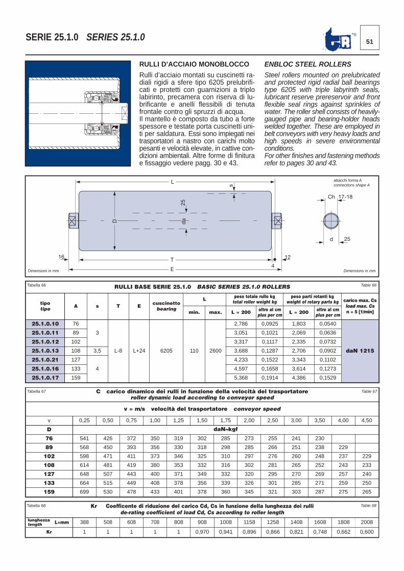
51®SERIE 25.1.0 SERIES 25.1.0
16
L
D
25
T
E 4
12
s
Ch 17-18
d 25
da
Dimensioni in mm Dimensions in mm
RULLI D’ACCIAIO MONOBLOCCO
Rulli d’acciaio montati su cuscinetti ra -diali rigidi a sfere tipo 6205 prelubrifi -cati e protetti con guarnizioni a triplolabirinto, precamera con riserva di lu -brificante e anelli flessibili di tenutafrontale contro gli spruzzi di acqua. Il mantello è composto da tubo a fortespessore e testate porta cuscinetti uni -ti per saldatura. Essi sono impiegati neitrasportatori a nastro con carichi moltopesanti e velocità elevate, in cattive con -dizioni ambientali. Altre forme di finiturae fissaggio vede re pagg. 30 e 43.
ENBLOC STEEL ROLLERS
Steel rollers mounted on prelubricatedand protected rigid radial ball bearingstype 6205 with triple labyrinth seals,lubricant reserve prereservoir and frontflexible seal rings against sprinkles ofwater. The roller shell consists of heavily-gauged pipe and bearing-holder headswelded together. These are employed inbelt conveyors with very heavy loads andhigh speeds in severe environmentalconditions. For other finishes and fastening methodsrefer to pages 30 and 43.
C carico dinamico dei rulli in funzione della velocità del trasportatore roller dynamic load according to conveyor speed
v = m/s velocità del trasportatore conveyor speed
v 0,25 0,50 0,75 1,00 1,25 1,50 1,75 2,00 2,50 3,00 3,50 4,00 4,50
D daN≈kgf
76 541 426 372 350 319 302 285 273 255 241 230
89 568 450 393 356 330 318 298 285 266 251 238 229
102 598 471 411 373 346 325 310 297 276 260 248 237 229
108 614 481 419 380 353 332 316 302 281 265 252 243 233
127 648 507 443 400 371 349 332 320 295 270 269 257 240
133 664 515 449 408 378 356 339 326 301 285 271 259 250
159 699 530 478 433 401 378 360 345 321 303 287 275 265
RULLI BASE SERIE 25.1.0 BASIC SERIES 25.1.0 ROLLERS
tipotipe A s T E cuscinetto
bearing
L peso totale rullo kgtotal roller weight kg
peso parti rotanti kgweight of rotary parts kg carico max. Cs
load max. Csn = 5 [1/min]min. max. L = 200 oltre al cm
plus per cm L = 200 oltre al cmplus per cm
25.1.0.10 76
3
L-8 L+24 6205 110 2600
2,786 0,0925 1,803 0,0540
daN 1215
25.1.0.11 89 3,051 0,1021 2,069 0,0636
25.1.0.12 102 3,317 0,1117 2,335 0,0732
25.1.0.13 108 3,5 3,688 0,1287 2,706 0,0902
25.1.0.21 127
4
4,233 0,1522 3,343 0,1102
25.1.0.16 133 4,597 0,1658 3,614 0,1273
25.1.0.17 159 5,368 0,1914 4,386 0,1529
Tabella 66 Table 66
Tabella 67 Table 67
Kr Coefficente di riduzione del carico Cd, Cs in funzione della lunghezza dei rullide-rating coefficient of load Cd, Cs according to roller length
lunghezzalength 388 508 608 708 808 908 1008 1158 1258 1408 1608 1808 2008
Kr 1 1 1 1 1 0,970 0,941 0,896 0,866 0,821 0,748 0,662 0,600
Tabella 68 Table 68
L=mm
attacchi forma Aconnections shape A
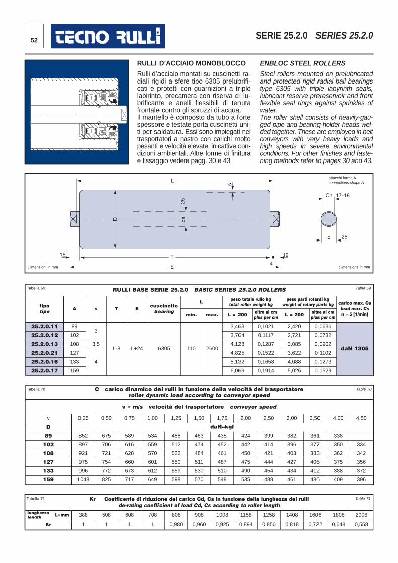
52 SERIE 25.2.0 SERIES 25.2.0
16
L
D
25
T
E 4
12
s
Ch 17-18
d 25
da
Dimensioni in mm Dimensions in mm
RULLI D’ACCIAIO MONOBLOCCO
Rulli d’acciaio montati su cuscinetti ra -diali rigidi a sfere tipo 6305 prelubrifi -cati e protetti con guarnizioni a triplolabirinto, precamera con riserva di lu -brificante e anelli flessibili di tenutafrontale contro gli spruzzi di acqua. Il mantello è composto da tubo a fortespessore e testate porta cuscinetti uni -ti per saldatura. Essi sono impiegati neitrasportatori a nastro con carichi moltopesanti e velocità elevate, in cattive con -dizioni ambientali. Altre forme di finiturae fissaggio vedere pagg. 30 e 43
ENBLOC STEEL ROLLERS
Steel rollers mounted on prelubricatedand protected rigid radial ball bearingstype 6305 with triple labyrinth seals,lubricant reserve prereservoir and frontflexible seal rings against sprinkles ofwater.The roller shell consists of heavily-gau-ged pipe and bearing-holder heads wel-ded together. These are employed in beltconveyors with very heavy loads andhigh speeds in severe environmentalconditions. For other finishes and faste-ning methods refer to pages 30 and 43.
C carico dinamico dei rulli in funzione della velocità del trasportatore roller dynamic load according to conveyor speed
v = m/s velocità del trasportatore conveyor speed
v 0,25 0,50 0,75 1,00 1,25 1,50 1,75 2,00 2,50 3,00 3,50 4,00 4,50
D daN≈kgf
89 852 675 589 534 488 463 435 424 399 382 361 338
102 897 706 616 559 512 474 452 442 414 396 377 350 334
108 921 721 628 570 522 484 461 450 421 403 383 362 342
127 975 754 660 601 550 511 487 475 444 427 406 375 356
133 996 772 673 612 559 530 510 490 454 434 412 388 372
159 1048 825 717 649 598 570 548 535 488 461 436 409 396
RULLI BASE SERIE 25.2.0 BASIC SERIES 25.2.0 ROLLERS
tipotipe A s T E cuscinetto
bearing
L peso totale rullo kgtotal roller weight kg
peso parti rotanti kgweight of rotary parts kg carico max. Cs
load max. Csn = 5 [1/min]min. max. L = 200 oltre al cm
plus per cm L = 200 oltre al cmplus per cm
25.2.0.11 893
L-8 L+24 6305 110 2600
3,463 0,1021 2,420 0,0636
daN 1305
25.2.0.12 102 3,764 0,1117 2,721 0,0732
25.2.0.13 108 3,5 4,128 0,1287 3,085 0,0902
25.2.0.21 127
4
4,825 0,1522 3,622 0,1102
25.2.0.16 133 5,132 0,1658 4,088 0,1273
25.2.0.17 159 6,069 0,1914 5,026 0,1529
Tabella 69 Table 69
Tabella 70 Table 70
Kr Coefficente di riduzione del carico Cd, Cs in funzione della lunghezza dei rullide-rating coefficient of load Cd, Cs according to roller length
lunghezzalength 388 508 608 708 808 908 1008 1158 1258 1408 1608 1808 2008
Kr 1 1 1 1 0,980 0,960 0,925 0,894 0,850 0,818 0,722 0,648 0,558
Tabella 71 Table 71
L=mm
attacchi forma Aconnections shape A
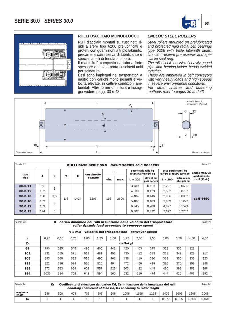
53®SERIE 30.0 SERIES 30.0
16
L
D
30
T
E 4
12
s
Ch 22
d 30
da
Dimensioni in mm Dimensions in mm
RULLI D’ACCIAIO MONOBLOCCO
Rulli d’acciaio montati su cuscinetti ri -gidi a sfere tipo 6206 prelubrificati eprotetti con guarnizioni a triplo labirinto,precamera con riserva di lubrificante especiali anelli di tenuta a labbro. Il mantello è composto da tubo a fortespessore e testate porta cuscinetti uni tiper saldatura.Essi sono impiegati nei trasportatori anastro con carichi molto pesanti e ve -locità elevate, in cattive condizioni am -bientali. Altre forme di finitura e fissag-gio vedere pagg. 30 e 43.
ENBLOC STEEL ROLLERS
Steel rollers mounted on prelubricatedand protected rigid radial ball bearingstype 6206 with triple labyrinth seals,lubricant reserve prereservoir and spe -cial lip seal ring.The roller shell consists of heavily-gagedpipe and bearing-holder heads weldedtogether.These are employed in belt conveyorswith very heavy loads and high speedsin severe environmental conditions. For other finishes and fasteningmethods refer to pages 30 and 43.
RULLI BASE SERIE 30.0 BASIC SERIES 30.0 ROLLERS
tipotipe A s T E cuscinetto
bearing
L peso totale rullo kgtotal roller weight kg
peso parti rotanti kgweight of rotary parts kg carico max. Cs
load max. Csn = 5 [1/min]min. max. L = 200 oltre al cm
plus per cm L = 200 oltre al cmplus per cm
30.0.11 893
L-8 L+24 6206 115 2600
3,739 0,119 2,291 0,0636
daN 1450
30.0.12 102 4,039 0,129 2,592 0,0732
30.0.13 108 3,5 4,404 0,146 2,956 0,0902
30.0.16 1334
5,407 0,183 3,959 0,1273
30.0.17 159 6,345 0,208 4,897 0,1529
30.0.19 194 6 9,307 0,332 7,872 0,2767
Tabella 72 Table 72
C carico dinamico dei rulli in funzione della velocità del trasportatore roller dynamic load according to conveyor speed
v = m/s velocità del trasportatore conveyor speed
v 0,25 0,50 0,75 1,00 1,25 1,50 1,75 2,00 2,50 3,00 3,50 4,00 4,50
D daN≈kgf
89 790 625 545 495 460 442 420 403 375 352 336 321
102 831 655 571 518 481 452 430 412 383 361 343 329 317
108 853 668 582 526 490 461 438 419 390 368 350 335 323
133 922 716 624 566 525 494 472 450 419 395 376 359 346
159 972 763 664 602 557 525 503 482 448 420 399 382 368
194 1036 814 708 642 594 560 532 510 474 447 425 407 392
Tabella 73 Table 73
Kr Coefficente di riduzione del carico Cd, Cs in funzione della lunghezza dei rullide-rating coefficient of load Cd, Cs according to roller length
lunghezzalength 388 508 608 708 808 908 1008 1158 1258 1408 1608 1808 2008
Kr 1 1 1 1 1 1 1 1 1 0,977 0,965 0,920 0,870
Tabella 74 Table 74
attacchi forma Aconnections shape A
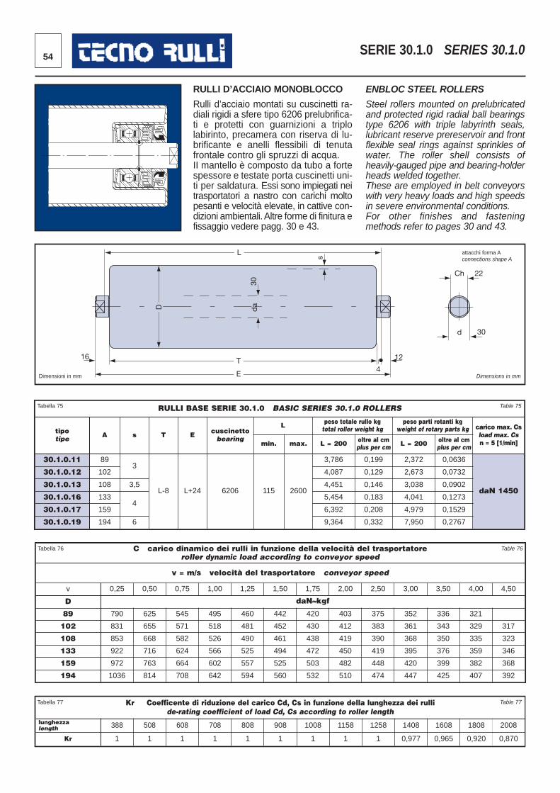
RULLI D’ACCIAIO MONOBLOCCO
Rulli d’acciaio montati su cuscinetti ra-diali rigidi a sfere tipo 6206 prelubrifica-ti e protetti con guarnizioni a triplolabirinto, precamera con riserva di lu-brificante e anelli flessibili di tenutafrontale contro gli spruzzi di acqua.II mantello è composto da tubo a fortespessore e testate porta cuscinetti uni-ti per saldatura. Essi sono impiegati neitrasportatori a nastro con carichi moltopesanti e velocità elevate, in cattive con-dizioni ambientali. Altre forme di finitura efissaggio vedere pagg. 30 e 43.
ENBLOC STEEL ROLLERS
Steel rollers mounted on prelubricatedand protected rigid radial ball bearingstype 6206 with triple labyrinth seals,lubricant reserve prereservoir and frontflexible seal rings against sprinkles ofwater. The roller shell consists ofheavily-gauged pipe and bearing-holderheads welded together. These are employed in belt conveyorswith very heavy loads and high speedsin severe environmental conditions. For other finishes and fasteningmethods refer to pages 30 and 43.
54 SERIE 30.1.0 SERIES 30.1.0
16
L
D
30
T
E 4
12
s
Ch 22
d 30
da
Dimensioni in mm Dimensions in mm
Kr Coefficente di riduzione del carico Cd, Cs in funzione della lunghezza dei rullide-rating coefficient of load Cd, Cs according to roller length
lunghezzalength 388 508 608 708 808 908 1008 1158 1258 1408 1608 1808 2008
Kr 1 1 1 1 1 1 1 1 1 0,977 0,965 0,920 0,870
Tabella 77 Table 77
RULLI BASE SERIE 30.1.0 BASIC SERIES 30.1.0 ROLLERS
tipotipe A s T E cuscinetto
bearing
L peso totale rullo kgtotal roller weight kg
peso parti rotanti kgweight of rotary parts kg carico max. Cs
load max. Csn = 5 [1/min]min. max. L = 200 oltre al cm
plus per cm L = 200 oltre al cmplus per cm
30.1.0.11 893
L-8 L+24 6206 115 2600
3,786 0,199 2,372 0,0636
daN 1450
30.1.0.12 102 4,087 0,129 2,673 0,0732
30.1.0.13 108 3,5 4,451 0,146 3,038 0,0902
30.1.0.16 1334
5,454 0,183 4,041 0,1273
30.1.0.17 159 6,392 0,208 4,979 0,1529
30.1.0.19 194 6 9,364 0,332 7,950 0,2767
Tabella 75 Table 75
C carico dinamico dei rulli in funzione della velocità del trasportatore roller dynamic load according to conveyor speed
v = m/s velocità del trasportatore conveyor speed
v 0,25 0,50 0,75 1,00 1,25 1,50 1,75 2,00 2,50 3,00 3,50 4,00 4,50
D daN≈kgf
89 790 625 545 495 460 442 420 403 375 352 336 321
102 831 655 571 518 481 452 430 412 383 361 343 329 317
108 853 668 582 526 490 461 438 419 390 368 350 335 323
133 922 716 624 566 525 494 472 450 419 395 376 359 346
159 972 763 664 602 557 525 503 482 448 420 399 382 368
194 1036 814 708 642 594 560 532 510 474 447 425 407 392
Tabella 76 Table 76
attacchi forma Aconnections shape A
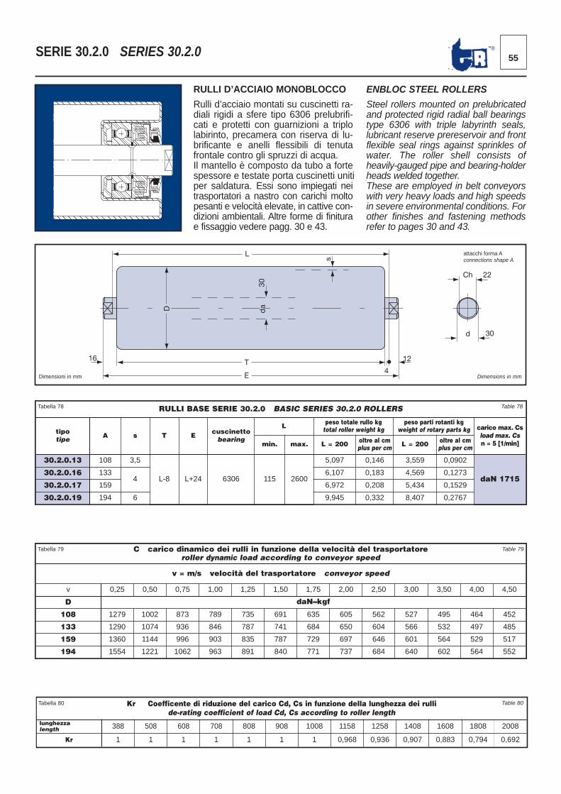
55®SERIE 30.2.0 SERIES 30.2.0
16
L
D
30
T
E 4
12
s
Ch 22
d 30
da
Dimensioni in mm Dimensions in mm
RULLI D’ACCIAIO MONOBLOCCO
Rulli d’acciaio montati su cuscinetti ra -diali rigidi a sfere tipo 6306 prelubrifi -cati e protetti con guarnizioni a triplolabirinto, precamera con riserva di lu -brificante e anelli flessibili di tenutafrontale contro gli spruzzi di acqua. Il mantello è composto da tubo a fortespessore e testate porta cuscinetti uni tiper saldatura. Essi sono impiegati neitrasportatori a nastro con carichi moltopesanti e velocità elevate, in cattive con -dizioni ambientali. Altre forme di finiturae fissaggio vedere pagg. 30 e 43.
ENBLOC STEEL ROLLERS
Steel rollers mounted on prelubricatedand protected rigid radial ball bearingstype 6306 with triple labyrinth seals,lubricant reserve prereservoir and frontflexible seal rings against sprinkles ofwater. The roller shell consists ofheavily-gauged pipe and bearing-holderheads welded together.These are employed in belt conveyorswith very heavy loads and high speedsin severe environmental conditions. Forother finishes and fastening methodsrefer to pages 30 and 43.
Kr Coefficente di riduzione del carico Cd, Cs in funzione della lunghezza dei rullide-rating coefficient of load Cd, Cs according to roller length
lunghezzalength 388 508 608 708 808 908 1008 1158 1258 1408 1608 1808 2008
Kr 1 1 1 1 1 1 1 0,968 0,936 0,907 0,883 0,794 0,692
Tabella 80 Table 80
RULLI BASE SERIE 30.2.0 BASIC SERIES 30.2.0 ROLLERS
tipotipe A s T E cuscinetto
bearing
L peso totale rullo kgtotal roller weight kg
peso parti rotanti kgweight of rotary parts kg carico max. Cs
load max. Csn = 5 [1/min]min. max. L = 200 oltre al cm
plus per cm L = 200 oltre al cmplus per cm
30.2.0.13 108 3,5
L-8 L+24 6306 115 2600
5,097 0,146 3,559 0,0902
daN 171530.2.0.16 133
46,107 0,183 4,569 0,1273
30.2.0.17 159 6,972 0,208 5,434 0,1529
30.2.0.19 194 6 9,945 0,332 8,407 0,2767
Tabella 78 Table 78
C carico dinamico dei rulli in funzione della velocità del trasportatore roller dynamic load according to conveyor speed
v = m/s velocità del trasportatore conveyor speed
v 0,25 0,50 0,75 1,00 1,25 1,50 1,75 2,00 2,50 3,00 3,50 4,00 4,50
D daN≈kgf
108 1279 1002 873 789 735 691 635 605 562 527 495 464 452
133 1290 1074 936 846 787 741 684 650 604 566 532 497 485
159 1360 1144 996 903 835 787 729 697 646 601 564 529 517
194 1554 1221 1062 963 891 840 771 737 684 640 602 564 552
Tabella 79 Table 79
attacchi forma Aconnections shape A
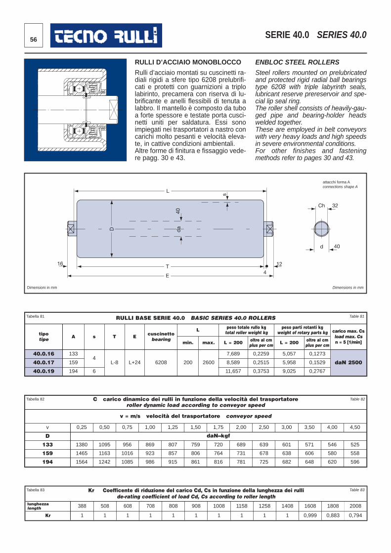
56 SERIE 40.0 SERIES 40.0
16
L
D
40
T
E 4
12
s
Ch 32
d 40
da
Dimensioni in mm Dimensions in mm
RULLI D’ACCIAIO MONOBLOCCO
Rulli d’acciaio montati su cuscinetti ra -diali rigidi a sfere tipo 6208 prelubrifi -cati e protetti con guarnizioni a triplolabirinto, precamera con riserva di lu -brificante e anelli flessibili di tenuta alabbro. Il mantello è composto da tuboa forte spessore e testate porta cusci-netti uni ti per saldatura. Essi sonoimpiegati nei trasportatori a nastro concarichi molto pesanti e velocità eleva-te, in cattive con dizioni ambientali. Altre forme di finitura e fissaggio vede-re pagg. 30 e 43.
ENBLOC STEEL ROLLERS
Steel rollers mounted on prelubricatedand protected rigid radial ball bearingstype 6208 with triple labyrinth seals,lubricant reserve prereservoir and spe-cial lip seal ring.The roller shell consists of heavily-gau-ged pipe and bearing-holder headswelded together. These are employed in belt conveyorswith very heavy loads and high speedsin severe environmental conditions. For other finishes and fasteningmethods refer to pages 30 and 43.
Kr Coefficente di riduzione del carico Cd, Cs in funzione della lunghezza dei rullide-rating coefficient of load Cd, Cs according to roller length
lunghezzalength 388 508 608 708 808 908 1008 1158 1258 1408 1608 1808 2008
Kr 1 1 1 1 1 1 1 1 1 1 0,999 0,883 0,794
Tabella 83 Table 83
RULLI BASE SERIE 40.0 BASIC SERIES 40.0 ROLLERS
tipotipe A s T E cuscinetto
bearing
L peso totale rullo kgtotal roller weight kg
peso parti rotanti kgweight of rotary parts kg carico max. Cs
load max. Csn = 5 [1/min]min. max. L = 200 oltre al cm
plus per cm L = 200 oltre al cmplus per cm
40.0.16 1334
L-8 L+24 6208 200 2600
7,689 0,2259 5,057 0,1273
daN 250040.0.17 159 8,589 0,2515 5,958 0,1529
40.0.19 194 6 11,657 0,3753 9,025 0,2767
Tabella 81 Table 81
C carico dinamico dei rulli in funzione della velocità del trasportatore roller dynamic load according to conveyor speed
v = m/s velocità del trasportatore conveyor speed
v 0,25 0,50 0,75 1,00 1,25 1,50 1,75 2,00 2,50 3,00 3,50 4,00 4,50
D daN≈kgf
133 1380 1095 956 869 807 759 720 689 639 601 571 546 525
159 1465 1163 1016 923 857 806 764 731 678 638 606 580 558
194 1564 1242 1085 986 915 861 816 781 725 682 648 620 596
Tabella 82 Table 82
attacchi forma Aconnections shape A
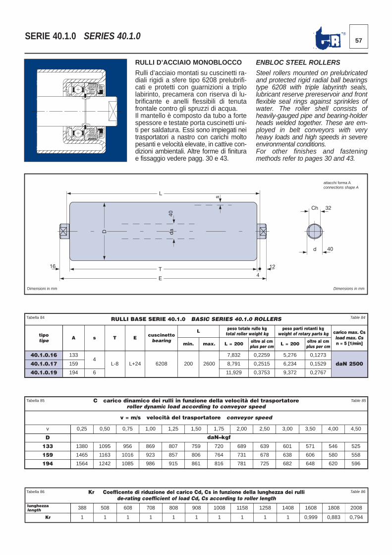
57®SERIE 40.1.0 SERIES 40.1.0
16
L
D
40
T
E 4
12
s
Ch 32
d 40
da
Dimensioni in mm Dimensions in mm
RULLI D’ACCIAIO MONOBLOCCO
Rulli d’acciaio montati su cuscinetti ra -diali rigidi a sfere tipo 6208 prelubrifi -cati e protetti con guarnizioni a triplolabirinto, precamera con riserva di lu -brificante e anelli flessibili di tenutafrontale contro gli spruzzi di acqua.Il mantello è composto da tubo a fortespessore e testate porta cuscinetti uni -ti per saldatura. Essi sono impiegati neitrasportatori a nastro con carichi moltopesanti e velocità elevate, in cattive con -dizioni ambientali. Altre forme di finiturae fissaggio vedere pagg. 30 e 43.
ENBLOC STEEL ROLLERS
Steel rollers mounted on prelubricatedand protected rigid radial ball bearingstype 6208 with triple labyrinth seals,lubricant reserve prereservoir and frontflexible seal rings against sprinkles ofwater. The roller shell consists ofheavily-gauged pipe and bearing-holderheads welded together. These are em-ployed in belt conveyors with veryheavy loads and high speeds in severeenvironmental conditions.For other finishes and fasteningmethods refer to pages 30 and 43.
Kr Coefficente di riduzione del carico Cd, Cs in funzione della lunghezza dei rullide-rating coefficient of load Cd, Cs according to roller length
lunghezzalength 388 508 608 708 808 908 1008 1158 1258 1408 1608 1808 2008
Kr 1 1 1 1 1 1 1 1 1 1 0,999 0,883 0,794
Tabella 86 Table 86
RULLI BASE SERIE 40.1.0 BASIC SERIES 40.1.0 ROLLERS
tipotipe A s T E cuscinetto
bearing
L peso totale rullo kgtotal roller weight kg
peso parti rotanti kgweight of rotary parts kg carico max. Cs
load max. Csn = 5 [1/min]min. max. L = 200 oltre al cm
plus per cm L = 200 oltre al cmplus per cm
40.1.0.16 1334
L-8 L+24 6208 200 2600
7,832 0,2259 5,276 0,1273
daN 250040.1.0.17 159 8,791 0,2515 6,234 0,1529
40.1.0.19 194 6 11,929 0,3753 9,372 0,2767
Tabella 84 Table 84
C carico dinamico dei rulli in funzione della velocità del trasportatore roller dynamic load according to conveyor speed
v = m/s velocità del trasportatore conveyor speed
v 0,25 0,50 0,75 1,00 1,25 1,50 1,75 2,00 2,50 3,00 3,50 4,00 4,50
D daN≈kgf
133 1380 1095 956 869 807 759 720 689 639 601 571 546 525
159 1465 1163 1016 923 857 806 764 731 678 638 606 580 558
194 1564 1242 1085 986 915 861 816 781 725 682 648 620 596
Tabella 85 Table 85
attacchi forma Aconnections shape A
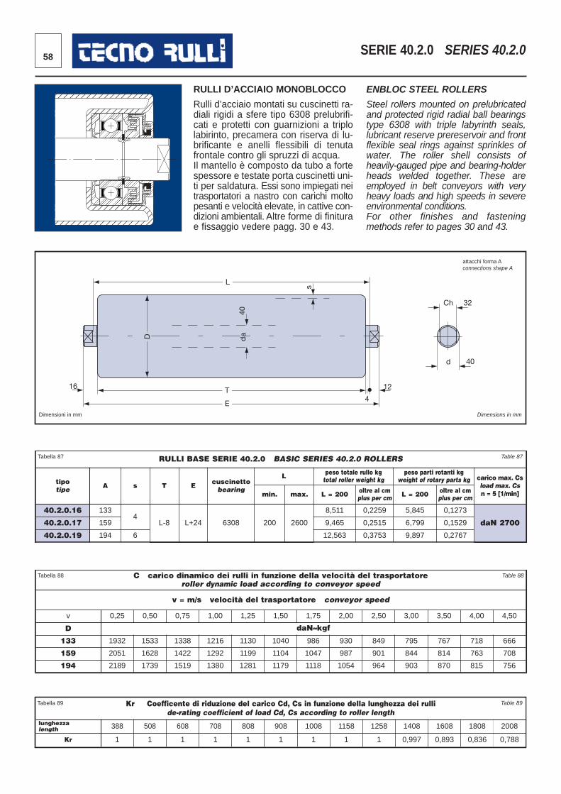
58 SERIE 40.2.0 SERIES 40.2.0
16
L
D
40
T
E 4
12
s Ch 32
d 40
da
Dimensioni in mm Dimensions in mm
RULLI D’ACCIAIO MONOBLOCCO
Rulli d’acciaio montati su cuscinetti ra -diali rigidi a sfere tipo 6308 prelubrifi -cati e protetti con guarnizioni a triplolabirinto, precamera con riserva di lu -brificante e anelli flessibili di tenutafrontale contro gli spruzzi di acqua. Il mantello è composto da tubo a fortespessore e testate porta cuscinetti uni -ti per saldatura. Essi sono impiegati neitrasportatori a nastro con carichi moltopesanti e velocità elevate, in cattive con -dizioni ambientali. Altre forme di finiturae fissaggio vedere pagg. 30 e 43.
ENBLOC STEEL ROLLERS
Steel rollers mounted on prelubricatedand protected rigid radial ball bearingstype 6308 with triple labyrinth seals,lubricant reserve prereservoir and frontflexible seal rings against sprinkles ofwater. The roller shell consists ofheavily-gauged pipe and bearing-holderheads welded together. These areemployed in belt conveyors with veryheavy loads and high speeds in severeenvironmental conditions.For other finishes and fasteningmethods refer to pages 30 and 43.
Kr Coefficente di riduzione del carico Cd, Cs in funzione della lunghezza dei rullide-rating coefficient of load Cd, Cs according to roller length
lunghezzalength 388 508 608 708 808 908 1008 1158 1258 1408 1608 1808 2008
Kr 1 1 1 1 1 1 1 1 1 0,997 0,893 0,836 0,788
Tabella 89 Table 89
RULLI BASE SERIE 40.2.0 BASIC SERIES 40.2.0 ROLLERS
tipotipe A s T E cuscinetto
bearing
L peso totale rullo kgtotal roller weight kg
peso parti rotanti kgweight of rotary parts kg carico max. Cs
load max. Csn = 5 [1/min]min. max. L = 200 oltre al cm
plus per cm L = 200 oltre al cmplus per cm
40.2.0.16 1334
L-8 L+24 6308 200 2600
8,511 0,2259 5,845 0,1273
daN 270040.2.0.17 159 9,465 0,2515 6,799 0,1529
40.2.0.19 194 6 12,563 0,3753 9,897 0,2767
Tabella 87 Table 87
C carico dinamico dei rulli in funzione della velocità del trasportatore roller dynamic load according to conveyor speed
v = m/s velocità del trasportatore conveyor speed
v 0,25 0,50 0,75 1,00 1,25 1,50 1,75 2,00 2,50 3,00 3,50 4,00 4,50
D daN≈kgf
133 1932 1533 1338 1216 1130 1040 986 930 849 795 767 718 666
159 2051 1628 1422 1292 1199 1104 1047 987 901 844 814 763 708
194 2189 1739 1519 1380 1281 1179 1118 1054 964 903 870 815 756
Tabella 88 Table 88
attacchi forma Aconnections shape A
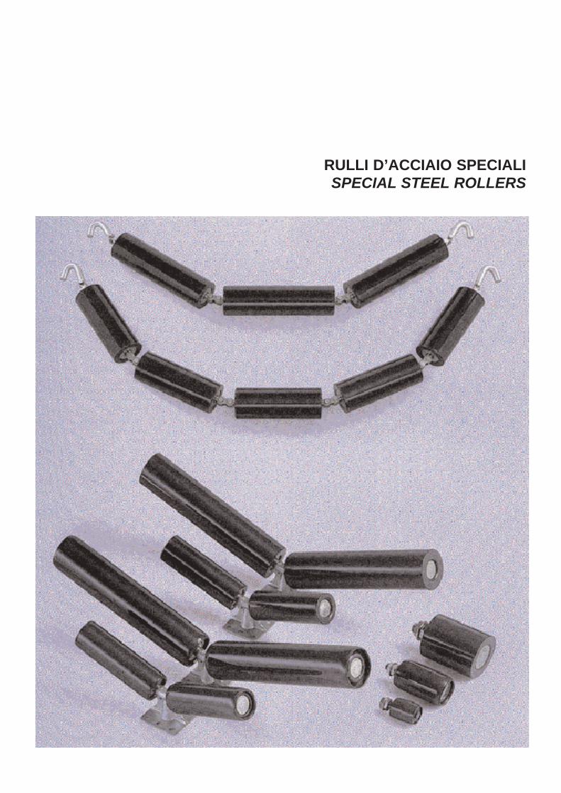
RULLI D’ACCIAIO SPECIALISPECIAL STEEL ROLLERS
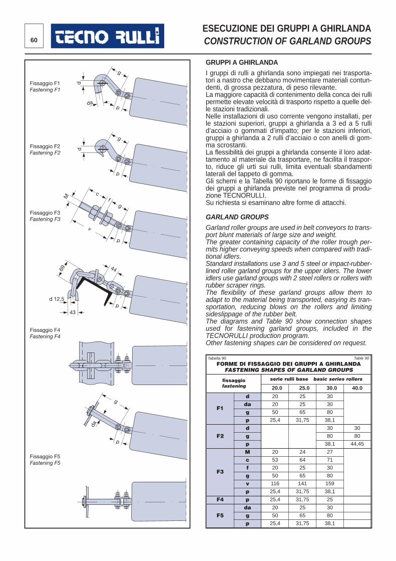
60
ESECUZIONE DEI GRUPPI A GHIRLANDACONSTRUCTION OF GARLAND GROUPS
GRUPPI A GHIRLANDA
I gruppi di rulli a ghirlanda sono impiegati nei trasporta -tori a nastro che debbano movimentare materiali contun -denti, di grossa pezzatura, di peso rilevante. La maggiore capacità di contenimento della conca dei rullipermette elevate velocità di trasporto rispetto a quelle del -le stazioni tradizionali.Nelle installazioni di uso corrente vengono installati, perle stazioni superiori, gruppi a ghirlanda a 3 ed a 5 rullid’acciaio o gommati d’impatto; per le stazioni inferiori,gruppi a ghirlanda a 2 rulli d’acciaio o con anelli di gom -ma scrostanti.La flessibilità dei gruppi a ghirlanda consente il loro adat -tamento al materiale da trasportare, ne facilita il traspor -to, riduce gli urti sui rulli, limita eventuali sbandamentilaterali del tappeto di gomma.Gli schemi e la Tabella 90 riportano le forme di fissaggiodei gruppi a ghirlanda previste nel programma di produ -zione TECNORULLI. Su richiesta si esaminano altre forme di attacchi.
GARLAND GROUPS
Garland roller groups are used in belt conveyors to trans-port blunt materials of large size and weight.The greater containing capacity of the roller trough per-mits higher conveying speeds when compared with tradi-tional idlers.Standard installations use 3 and 5 steel or impact-rubber-lined roller garland groups for the upper idiers. The loweridlers use garland groups with 2 steel rollers or rollers withrubber scraper rings.The flexibility of these garland groups allow them toadapt to the material being transported, easying its tran-sportation, reducing blows on the rollers and limitingsideslippage of the rubber belt.The diagrams and Table 90 show connection shapesused for fastening garland groups, included in theTECNORULLI production program.Other fastening shapes can be considered on request.
dap
gd
p
g
d
p
gf
c
69M
v
44
pd 12,5
43
p
g
da
Fissaggio F1Fastening F1
Fissaggio F2Fastening F2
Fissaggio F3Fastening F3
Fissaggio F4Fastening F4
Fissaggio F5Fastening F5
FORME DI FISSAGGIO DEI GRUPPI A GHIRLANDAFASTENING SHAPES OF GARLAND GROUPS
fissaggiofastening
serie rulli base basic series rollers
20.0 25.0 30.0 40.0
F1
d 20 25 30
da 20 25 30
g 50 65 80
p 25,4 31,75 38,1
F2d 30 30
g 80 80
p 38,1 44,45
F3
M 20 24 27
c 53 64 71
f 20 25 30
g 50 65 80
v 116 141 159
p 25,4 31,75 38,1
F4 p 25,4 31,75 25
F5da 20 25 30
g 50 65 80
p 25,4 31,75 38,1
Tabella 90 Table 90
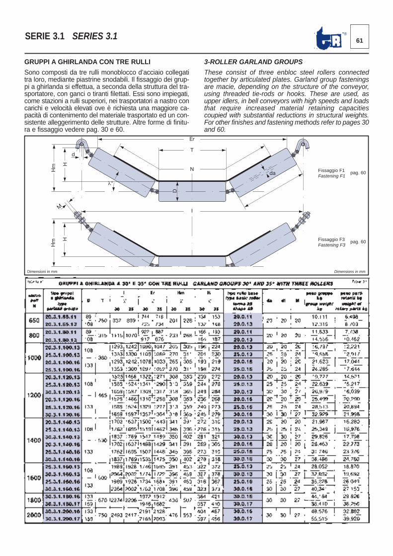
61®SERIE 3.1 SERIES 3.1
GRUPPI A GHIRLANDA CON TRE RULLI
Sono composti da tre rulli monoblocco d’acciaio collegatitra loro, mediante piastrine snodabili. Il fissaggio dei grup -pi a ghirlanda si effettua, a seconda della struttura del tra -sportatore, con ganci o tiranti filettati. Essi sono impiegati,come stazioni a rulli superiori, nei trasportatori a nastro concarichi e velocità elevati ove è richiesta una maggiore ca -pacità di contenimento del materiale trasportato ed un con -sistente alleggerimento delle strutture. Altre forme di finitu-ra e fissaggio vedere pag. 30 e 60.
3-ROLLER GARLAND GROUPS
These consist of three enbloc steel rollers connectedtogether by articulated plates. Garland group fasteningsare macie, depending on the structure of the conveyor,using threaded tie-rods or hooks. These are used, asupper idlers, in bell conveyors with high speeds and loadsthat require increased material retaining capacitiescoupied with substantial reductions in structural weights.For other finishes and fastening methods refer to pages 30and 60.
Er
d
λ°
Hm
H
D
T
N
I
da
Hm
H
M
Dimensioni in mm Dimensions in mm
Fissaggio F1Fastening F1
pag. 60
Fissaggio F3Fastening F3
pag. 60
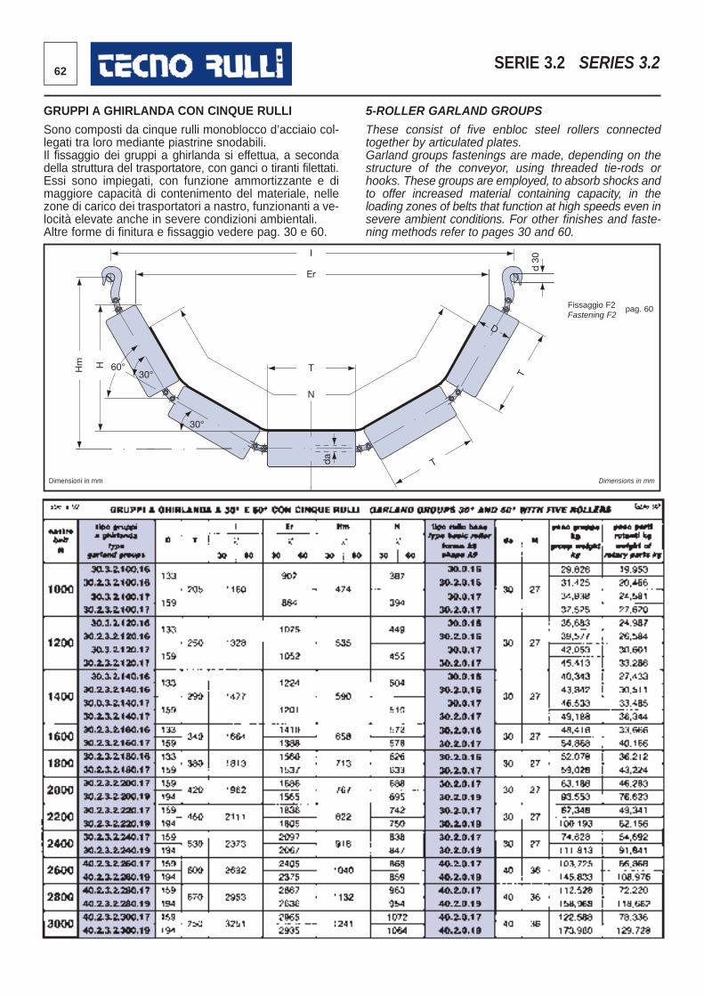
62 SERIE 3.2 SERIES 3.2
GRUPPI A GHIRLANDA CON CINQUE RULLI
Sono composti da cinque rulli monoblocco d’acciaio col -legati tra loro mediante piastrine snodabili. Il fissaggio dei gruppi a ghirlanda si effettua, a secondadella struttura del trasportatore, con ganci o tiranti filettati.Essi sono impiegati, con funzione ammortizzante e dimaggiore capacità di contenimento del materiale, nellezone di carico dei trasportatori a nastro, funzionanti a ve -locità elevate anche in severe condizioni ambientali. Altre forme di finitura e fissaggio vedere pag. 30 e 60.
5-ROLLER GARLAND GROUPS
These consist of five enbloc steel rollers connectedtogether by articulated plates.Garland groups fastenings are made, depending on thestructure of the conveyor, using threaded tie-rods orhooks. These groups are employed, to absorb shocks andto offer increased material containing capacity, in theloading zones of belts that function at high speeds even insevere ambient conditions. For other finishes and faste-ning methods refer to pages 30 and 60.
T
I
Er
T
N
T Hm
H
60° 30°
30°
d 3
0
da
D
Dimensioni in mm Dimensions in mm
Fissaggio F2Fastening F2
pag. 60
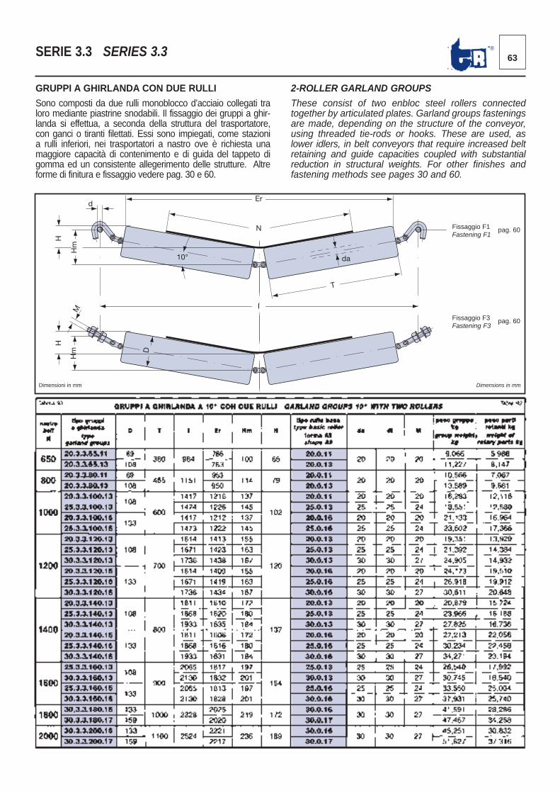
63®SERIE 3.3 SERIES 3.3
2-ROLLER GARLAND GROUPS
These consist of two enbloc steel rollers connectedtogether by articulated plates. Garland groups fasteningsare made, depending on the structure of the conveyor,using threaded tie-rods or hooks. These are used, aslower idlers, in belt conveyors that require increased beltretaining and guide capacities coupled with substantialreduction in structural weights. For other finishes andfastening methods see pages 30 and 60.
GRUPPI A GHIRLANDA CON DUE RULLI
Sono composti da due rulli monoblocco d’acciaio col legati traloro mediante piastrine snodabili. Il fissaggio dei gruppi a ghir-landa si effettua, a seconda della struttura del trasportatore,con ganci o tiranti filettati. Essi sono impiegati, come stazionia rulli inferiori, nei trasportatori a nastro ove è richiesta unamaggiore capacità di contenimento e di guida del tappeto digomma ed un consistente allegerimento delle strutture. Altreforme di finitura e fissaggio vedere pag. 30 e 60.
Hm
H
m
H
H
M
Er d
10°
N
I
T
da
D
Dimensioni in mm Dimensions in mm
Fissaggio F1Fastening F1
pag. 60
Fissaggio F3Fastening F3
pag. 60
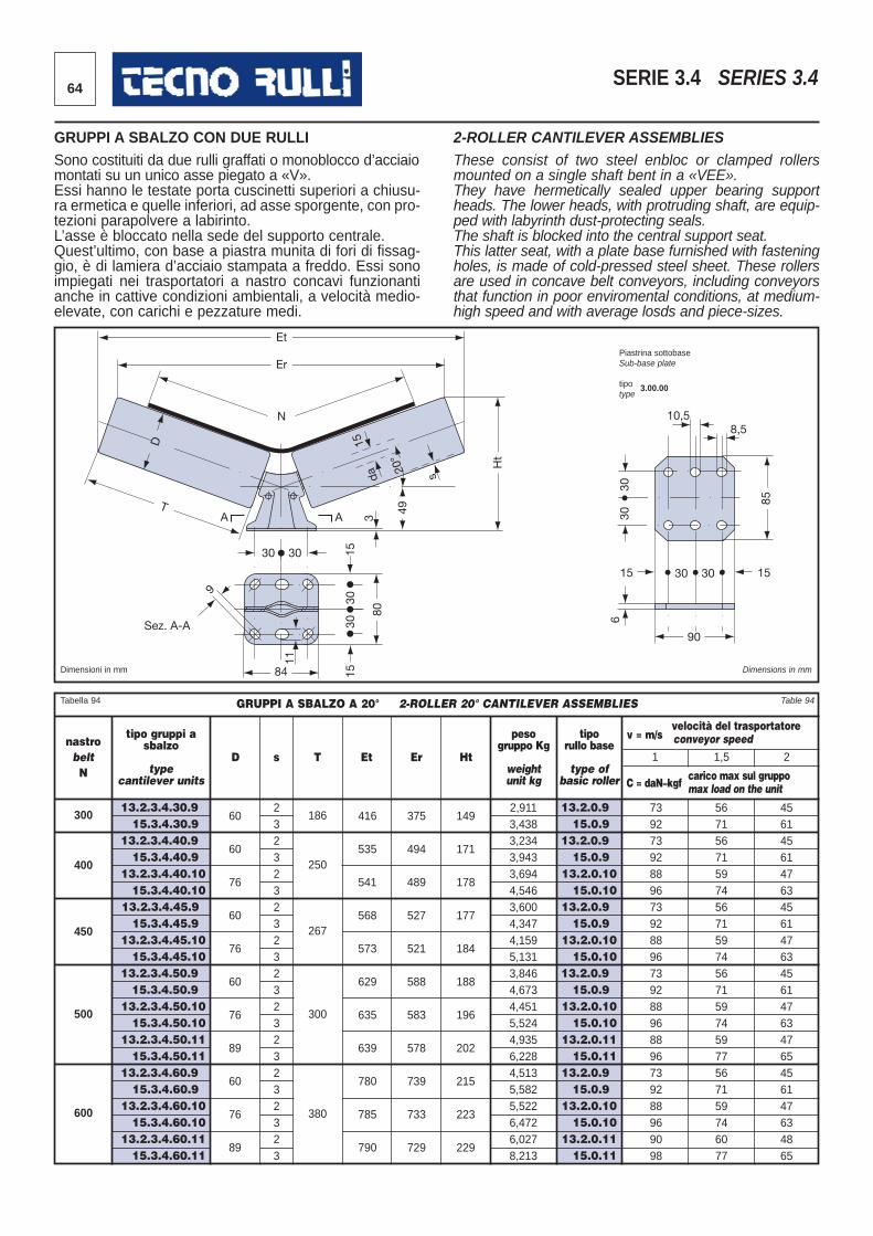
13.2.3.4.30.915.3.4.30.9
13.2.3.4.40.9 15.3.4.40.9
13.2.3.4.40.1015.3.4.40.10
13.2.3.4.45.9 15.3.4.45.9
13.2.3.4.45.1015.3.4.45.10
13.2.3.4.50.9 15.3.4.50.9
13.2.3.4.50.1015.3.4.50.10
13.2.3.4.50.1115.3.4.50.11
13.2.3.4.60.9 15.3.4.60.9
13.2.3.4.60.1015.3.4.60.10
13.2.3.4.60.1115.3.4.60.11
64 SERIE 3.4 SERIES 3.4
GRUPPI A SBALZO CON DUE RULLISono costituiti da due rulli graffati o monoblocco d’acciaiomontati su un unico asse piegato a «V».Essi hanno le testate porta cuscinetti superiori a chiusu-ra ermetica e quelle inferiori, ad asse sporgente, con pro-tezioni parapolvere a labirinto.L’asse è bloccato nella sede del supporto centrale.Quest’ultimo, con base a piastra munita di fori di fissag-gio, è di lamiera d’acciaio stampata a freddo. Essi sonoimpiegati nei trasportatori a nastro concavi funzionantianche in cattive condizioni ambientali, a velocità medio-elevate, con carichi e pezzature medi.
2-ROLLER CANTILEVER ASSEMBLIESThese consist of two steel enbloc or clamped rollersmounted on a single shaft bent in a «VEE».They have hermetically sealed upper bearing supportheads. The lower heads, with protruding shaft, are equip-ped with labyrinth dust-protecting seals.The shaft is blocked into the central support seat.This latter seat, with a plate base furnished with fasteningholes, is made of cold-pressed steel sheet. These rollersare used in concave belt conveyors, including conveyorsthat function in poor enviromental conditions, at medium-high speed and with average losds and piece-sizes.
Et
Er
N
15
da 20
°
s
30
9
Sez. A-A
30
84
3
30
80
Ht
30
49 85
6 30
30
30 15 15 30
90
10,5 8,5
15
11
15
A A T
D
Dimensioni in mm Dimensions in mm
GRUPPI A SBALZO A 20° 2-ROLLER 20° CANTILEVER ASSEMBLIES
nastrobeltN
D s T Et Er Ht
tipo gruppi asbalzo
typecantilever units
pesogruppo Kg
weightunit kg
tiporullo base
type ofbasic roller
velocità del trasportatorev = m/s conveyor speed
carico max sul gruppoC = daN≈kgf max load on the unit
60
60
76
60
76
60
76
89
60
76
89
416
535
541
568
573
629
635
639
780
785
790
375
494
489
527
521
588
583
578
739
733
729
149
171
178
177
184
188
196
202
215
223
229
300 186
400
450
500
600
2323 232323232323232323
2,9113,4383,2343,9433,6944,5463,6004,3474,1595,1313,8464,6734,4515,5244,9356,2284,5135,5825,5226,4726,0278,213
73927392889673928896739288968896739288969098
56715671597456715974567159745977567159746077
45614561476345614763456147634765456147634865
13.2.0.915.0.9
13.2.0.9 15.0.9
13.2.0.1015.0.10
13.2.0.915.0.9
13.2.0.1015.0.10
13.2.0.915.0.9
13.2.0.1015.0.10
13.2.0.1115.0.11
13.2.0.915.0.9
13.2.0.1015.0.10
13.2.0.1115.0.11
1 1,5 2
250
267
300
380
Tabella 94 Table 94
Piastrina sottobaseSub-base plate
tipo 3.00.00type
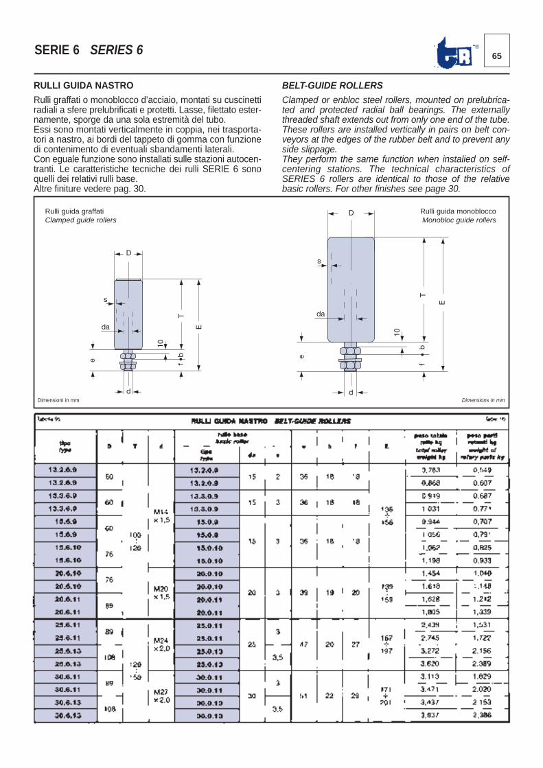
65®SERIE 6 SERIES 6
RULLI GUIDA NASTRO
Rulli graffati o monoblocco d’acciaio, montati su cuscinettiradiali a sfere prelubrificati e protetti. Lasse, filettato ester-namente, sporge da una sola estremità del tubo. Essi sono montati verticalmente in coppia, nei trasporta -tori a nastro, ai bordi del tappeto di gomma con funzionedi contenimento di eventuali sbandamenti laterali. Con eguale funzione sono installati sulle stazioni autocen -tranti. Le caratteristiche tecniche dei rulli SERIE 6 sonoquelli dei relativi rulli base. Altre finiture vedere pag. 30.
BELT-GUIDE ROLLERS
Clamped or enbloc steel rollers, mounted on prelubrica-ted and protected radial ball bearings. The externallythreaded shaft extends out from only one end of the tube. These rollers are installed vertically in pairs on belt con-veyors at the edges of the rubber belt and to prevent anyside slippage.They perform the same function when instalied on self-centering stations. The technical characteristics ofSERIES 6 rollers are identical to those of the relativebasic rollers. For other finishes see page 30.
Rulli guida graffatiClamped guide rollers
Rulli guida monobloccoMonobloc guide rollers
D
s
da
T
E
e f b
d
D
s
da
T
E
e
10
f
b
d
10
Dimensioni in mm Dimensions in mm
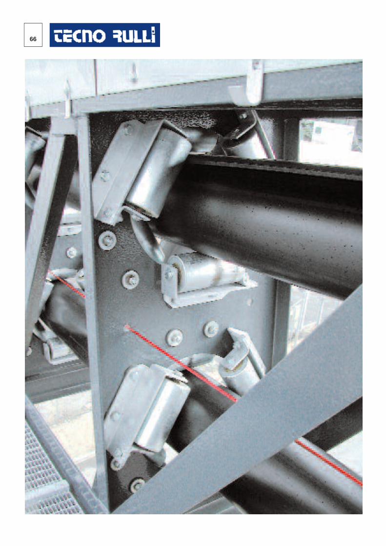
66
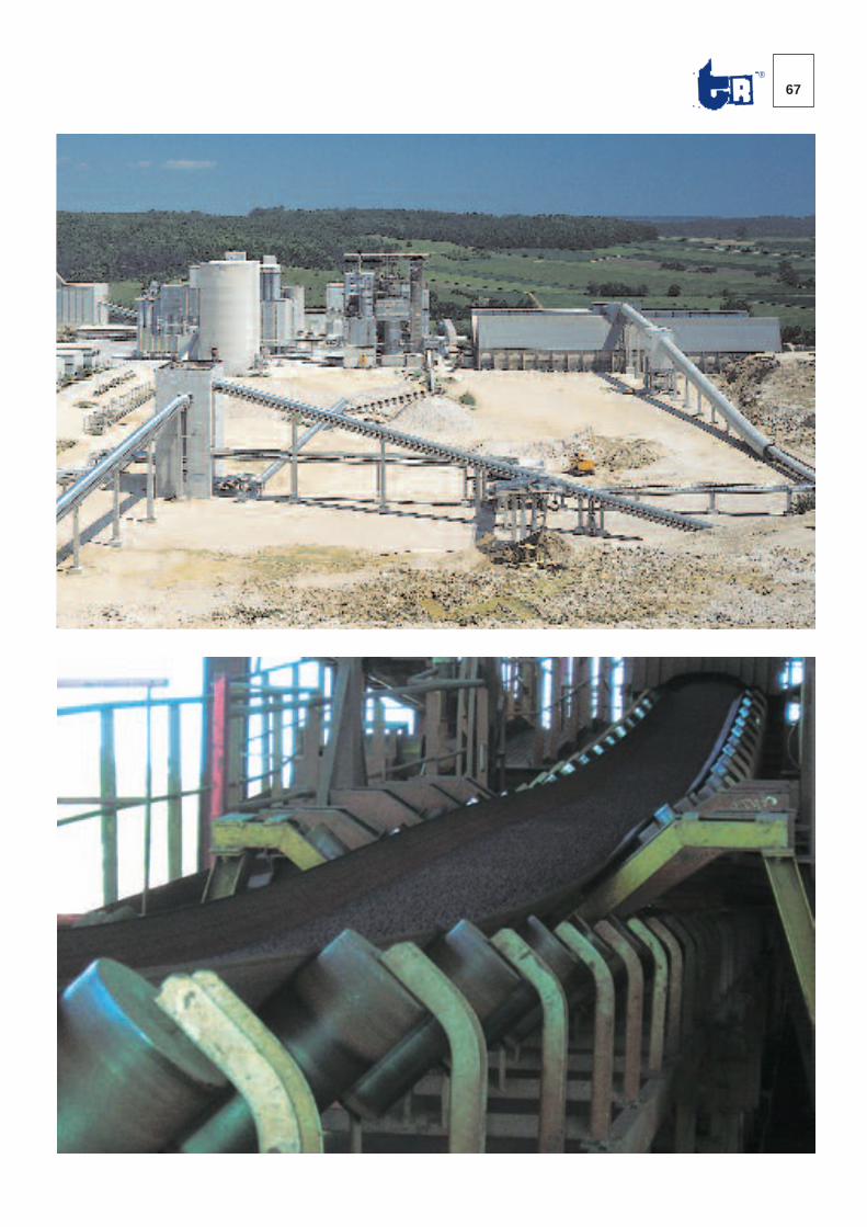
67®
68
DESCRIZIONE DEI RULLI DI PVC E PVC-ACCIAIODESCRIPTION OF THE PVC AND PVC-STEEL ROLLERS
DESCRIZIONE DEI RULLI DI PVC E PVC-ACCIAIOQuesti rulli, per le caratteristiche proprie dei materiali cheli compongono, sono impiegati nei trasportatori funzio-nanti in condizioni ambientali altamente corrosive. Essi, costruiti a regola d’arte, posseggono i requisiti de -scritti per i Rulli d’acciaio a pag. 4.
MANTELLO DEL RULLONella Serie 21.0 il tubo è di Pvc 312, ricavato per estru -sione di resina di poli-cloruro di vinile purissimo, esenteda cariche plastificanti e stabilizzato con esclusione di salidi piombo, conformemente alle NORME ISO 7441-7448,ISO 161-78 e 8061-62. Il polimero impiegato è completa -mente atossico. I tubi utilizzati dalla TECNORULLI pre -sentano le seguenti caratteristiche:- Resistenza meccanica a trazione Rm = 500-550Kg/cm2, ASTM-D-638.- Durezza 80-84 Shore D, ASTM-D-676. Il Pvc 312 è dif-ficilmente infiammabile, è autoestinguente e possiede inmodo particolare eccellenti doti di resisten za agli acidi,alle basi ed all’abrasione.Nella Serie 21.1.0 il tubo è d’acciaio tipo Fe360(Resistenza meccanica a trazione Rm min. = 400 N/mm2)o altri ac ciai come descritto per i Rulli d’Acciaio a pag. 4.
TESTATE PORTA CUSCINETTISono ottenute per stampaggio di resina termoplasticapoliammidica tipo 66, autoestinguente, non gocciolante erin forzata con microsfere di vetro. Le sedi di alloggiamentodei cuscinetti sono calibrate a tolleranza ISO M7. Esse so -no fissate solidamente al tubo con adesivo cianoacrilico.
ASSEÈ costituito da tondo d’acciaio trafilato diametro 20 mm,ricavato da laminato a caldo normalizzato e calibrato inconformità alle NORME ISO.
CUSCINETTISono radiali rigidi a sfere, tipo 6204, delle migliori mar che mon-diali costruiti in conformità alle Raccomandazio ni ISO (dimen-sioni d’ingombro secondo ISO R15-UNI 4259; dimensioni dellescanalature secondo ISO R15) e della norma DIN 625.
PROTEZIONILe guarnizioni a doppio labbro, ricavate nelle testate por -ta cuscinetti, impediscono la perdita di grasso all’internodel rullo. All’esterno dei cuscinetti le protezioni sono as -sicurate da tripli labirinti di resina poliammidica superte-nace rinforzata con microsfere di vetro. Esse incorpora-no, per la tenuta assiale, anelli a sezione toroidale digomma nitrilica. La giusta riserva di grasso al litio consen-te la lu brificazione a vita dei cuscinetti e dei labirinti.
RODAGGIO E CONTROLLO QUALITÀII rullo, ad assemblaggio ultimato, viene fatto ruotare adalta velocità per ottenere l’uniforme distribuzione delgras so sia nei cuscinetti che nei labirinti e per consentireil mutuo adattamento delle varie parti che lo compongo-no. Il collaudo finale verifica il controllo dimensionale delrul lo ed il valore della coppia resistente all’avviamento.
DESCRIPTION OF THE PVC AND PVC-STEEL ROLLERSThese rollers, because of the characteristics of the materialsof which they are made, are used in conveyors that operatein highly corrosive environmental conditions. These rollers,manufactured according to the standards of the trade, pos-sess the prerequisites described for Steel Rollers on page 4.
ROLLER SHELLIn Series 21.0 the tube is made of PVC 312, manufacturedby extrusion of highly pure polyvinyl chloride resin, entirelyfree of plasticizing fillers and stabilized with exclusion of leadsalts, in compliance with ISO 7441-7448, ISO 161-78 andISO 8061-62 STANDARDS. The polymer employed is abso-lutely non-toxic. The tubes used by TECNORULLI have thefollowing characteristics:- Resistance to tensile stress Rm = 500-550 Kg/cm2, ASTMD-638.- Shore D hardness 80-84, ASTM D-676.PVC 312 is difficult to burn and is self-extinguishing. In par-ticular it possesses excellent properties of resistance toacids, bases and abrasion.In series 21.1.0 tube is made of steel type Fe360 (resistan-ce to tensile stress Rm min. = 400 N/mm2) or other steels asdescribed for Steel Rollers on page 4.
BEARING HOUSINGSThese are made by molding of type 66 polyamide thermo-plastic resin that is self-extinguishing, non-dripping and rein-forced with glass microspheres. Bearing housing seats arecalibrated to ISO M7 tolerances. They are solidly fastened tothe tube by a cyanoacrylate adhesive.
SHAFTThis consists of a 20 mm diameter drawn steel rod madefrom normalized hot rolled steel plate calibrated in com -pliance with ISO STANDARDS.
BEARINGSType 6204 rigid radial ball bearings of top world brands builtin compliance with ISO Recommendations (overall dimen-sione according to ISO R15-UNI 4259; groove dimensionsaccording to ISO R15) and at the norm DIN 625.
SEALSDouble-lip seals, machined in the bearing support heads,prevent grease leakage inside the roller. Seals external tothe bearing consist of triple labyrinths made of super-strong polyamide resin reinforced with glass microsphe-res. These incorporate axial seal, toroidal-section rings,made of nitryl rubber. A proper reserve of lithium greaseguarantees life-long lubrication of the bearings and thelabyrinth seals.
RUNNING-IN AND QUALITY CONTROLRollers, upon completion of assembly, are made to rotate athigh speed to achieve uniform distribution of grease in bothbearings and labyrinth seals and to permit adaption of thevarious partes that compose the assembly. Final testingincludes dimension checks on the roller and measurementof start-up resistance torque.
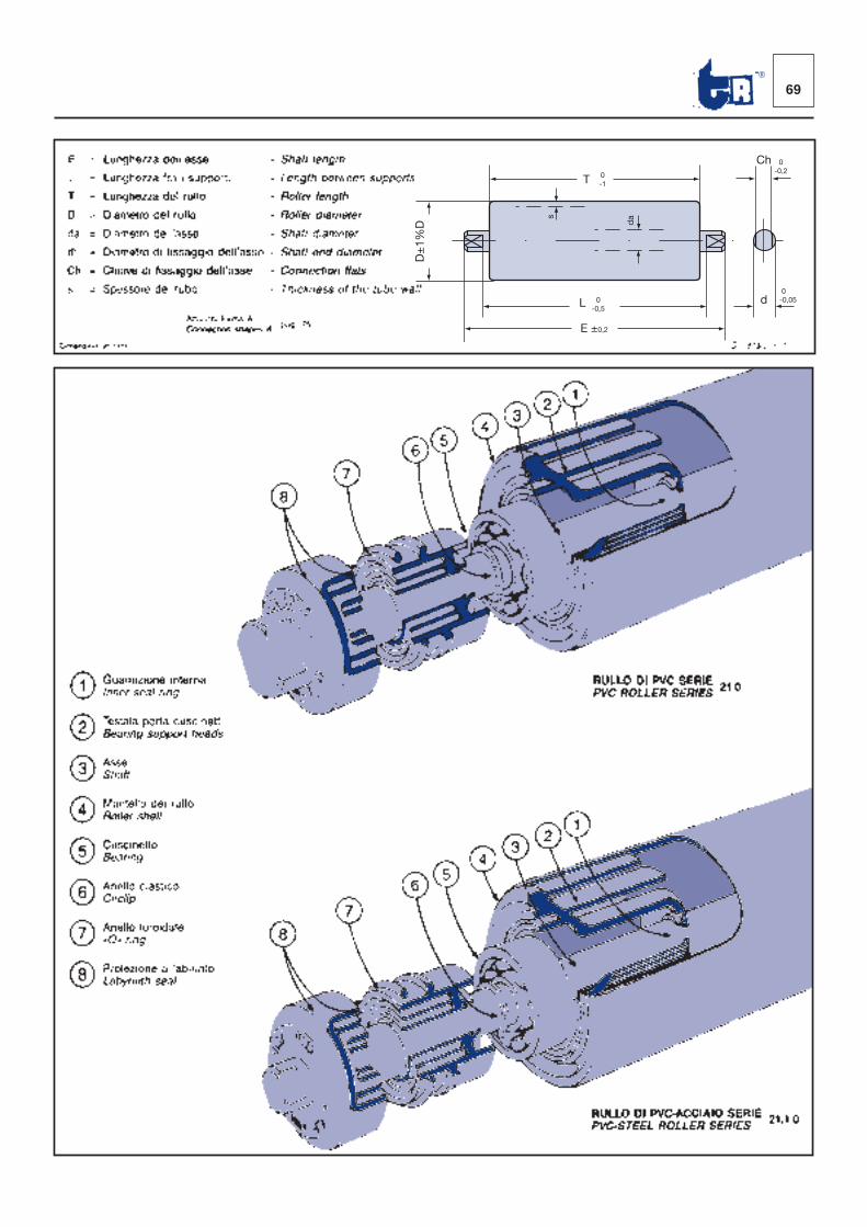
69®
T
Ch
d
0 -1
D±
1%D
s
da
L 0 -0,5
E ±0,2
0 -0,2
0 -0,05
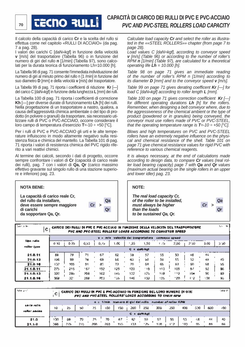
70
CAPACITÀ DI CARICO DEI RULLI DI PVC E PVC-ACCIAIOPVC AND PVC-STEEL ROLLERS LOAD CAPACITY
Il calcolo della capacità di carico Cr e la scelta del rullo sieffettua come nel capitolo «RULLI DI ACCIAIO» (da pag.7 a pag. 28).I valori dei carichi C [daN≈kgf] in funzione della velocitàv [m/s] del trasportatore (Tabella 96) o in funzione delnume ro di giri del rullo n [1/min] (Tabella 97), sono calco-lati per la durata teorica di funzionamento Lh=10.000 [h].
La Tabella 98 di pag. 71 consente l’immediata individua zione delnumero di giri al minuto primo del rullo n [1 /min] in funzione delsuo diametro D [mm] e della velocità v [m/s] del trasportatore.
La Tabella 99 di pag. 71 riporta i coefficienti di riduzione Kr [—]del carico C [daN≈kgf] in funzione della lunghezza L [mm] dei rulli.
La Tabella 100 di pag. 71 riporta i coefficienti di correzioneKh [—] per diverse durate di funzionamento Lh [h] dei rulli. Nella progettazione di un trasportatore a nastro, qualora, acau sa dell’aggressività chimica ambientale o del tipo di pro-dotto (in polvere o granuli) da trasportare, sia necessario uti-lizzare rulli di PVC o PVC-ACCIAIO, occorre considerare illoro cam po di temperatura d’esercizio T=-10 ÷ +50 [°C].
Per i rulli di PVC e PVC-ACCIAIO gli urti e le alte tempe -rature influiscono in modo altamente negativo sulla resi -stenza fisica e chimica del mantello. La Tabella 101 di pag.71 riporta i valori di resistenza chi mica del PVC rigido rife-rito a vari reattivi chimici.
Al termine dei calcoli, secondo i dati di progetto, occorresempre confrontare i valori di Cr (capacità di carico realedei rulli), pag. 7 con i valori di Qa, Qr (carico massimoeffettivo gravante sul singolo rullo di una stazione superio -re e inferiore) pag. 23.
Calculate load capacity Cr and select the roller as illustra-ted in the ««STEEL ROLLERS»» chapter (from page 7 topage 28).Load values C [daN=kgf], according to conveyor speedv [m/s] (Table 96) or according to the number of roller’sRPM n [1/min] (Table 97), are calculated for a theoreticaloperating life Lh = 10.000 [h].
Table 98 on page 71 gives an immediate readingof the number of roller’s RPM n [1/min] according toits diameter D [mm] and to the conveyor speed v [m/s].
Table 99 on page 71 gives derating coefficent Kr [—] forload C [daN≈kgf] according to roller length L [mm].
Table 100 on page 71 gives correction coefficient Kr [—]for different operating durations Lh [h] for the rollers.Remember, when designing a belt conveyor where, due tothe aggressiveness of the chemical ambient or the type ofproduct (powdered or in granules) being conveyed, theconveyor must use rollers made of PVC or PVC-STEEL,that the operating temperature range is T=-10 ÷ +50 [°C].
Blows and high temperatures on PVC and PVC-STEELrollers have an extremely negative influence on the physi-cal and chemical resistance of the shell. Table 101 onpage 71 give chemical resistance values for rigid PVC withreference to various chemical reagents.
It is always necessary, at the end of calculations madeaccording to design data, to compare Cr values (real rol-ler load bearing capacity) page 7 with Qa and Qr values(maximum actual bearing on the single rollers in an upperand lower idler) pag. 23.
NOTA BENE:
La capacità di carico reale Cr,del rullo da installare, Qadeve essere sempre maggiore Cr >di carichi Qrda sopportare Qa, Qr.
NOTE:
The real load capacity Cr,of the roller to be installed, Qamust always be higher Cr >than the loads Qrto be sustained Qa, Qr.
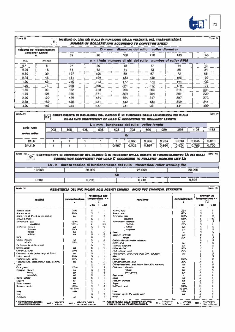
71®
D = mm diametro del rullo roller diameter
n = 1/min numero di giri del rullo number of roller RPM
L = mm lunghezza del rullo roller lenght
Kr
Lh - h durata teorica di funzionamento del rullo theoretical roller working life
Kh
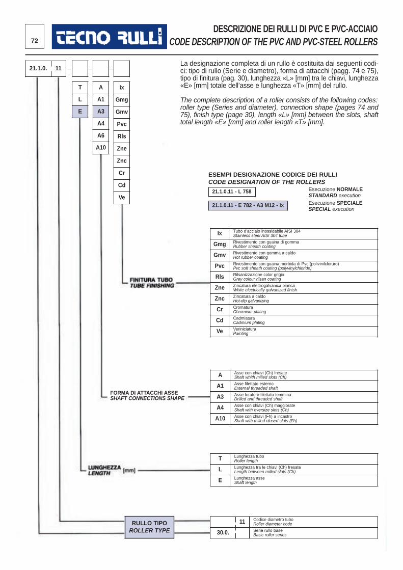
72
DESCRIZIONE DEI RULLI DI PVC E PVC-ACCIAIOCODE DESCRIPTION OF THE PVC AND PVC-STEEL ROLLERS
La designazione completa di un rullo è costituita dai seguenti codi -ci: tipo di rullo (Serie e diametro), forma di attacchi (pagg. 74 e 75),tipo di finitura (pag. 30), lunghezza «L» [mm] tra le chiavi, lunghezza«E» [mm] totale dell’asse e lunghezza «T» [mm] del rullo.
The complete description of a roller consists of the following codes:roller type (Series and diameter), connection shape (pages 74 and75), finish type (page 30), length «L» [mm] between the slots, shafttotal length «E» [mm] and roller length «T» [mm].
Ix Tubo d’acciaio inossidabile AISI 304Stainless steel AISI 304 tube
Gmg Rivestimento con guaina di gommaRubber sheath coating
Gmv Rivestimento con gomma a caldoHot rubber coating
Pvc Rivestimento con guaina morbida di Pvc (polivinilcloruro)Pvc soft sheath coating (polyvinylchloride)
Rls Rilsanizzazione color grigioGrey colour rilsan coating
Zne Zincatura elettrogalvanica biancaWhite electrically galvanized finish
Znc Zincatura a caldoHot-dip galvanizing
Cr CromaturaChromium plating
Cd CadmiaturaCadmium plating
Ve VeriniciaturaPainting
A Asse con chiavi (Ch) fresateShaft whith milled slots (Ch)
A1 Asse filettato esternoExternal threaded shaft
A3 Asse forato e filettato femminaDrilled and threaded shaft
A4 Asse con chiavi (Ch) maggiorateShaft with oversize slots (Ch)
A10 Asse con chiavi (Fh) a incastroShaft with milled closed slots (Fh)
T Lunghezza tuboRoller length
L Lunghezza tra le chiavi (Ch) fresateLength between milled slots (Ch)
E Lunghezza asseShaft length
11 Codice diametro tuboRoller diameter code
30.0. Serie rullo baseBasic roller series
RULLO TIPOROLLER TYPE
T
L
E
21.1.0. 11
A
A1
A3
A4
A6
A10
Ix
Gmg
Gmv
Pvc
Rls
Zne
Znc
Cr
Cd
Ve21.1.0.11 - L 758
21.1.0.11 - E 782 - A3 M12 - Ix
ESEMPI DESIGNAZIONE CODICE DEI RULLICODE DESIGNATION OF THE ROLLERS
Esecuzione NORMALESTANDARD executionEsecuzione SPECIALESPECIAL execution
FORMA DI ATTACCHI ASSESHAFT CONNECTIONS SHAPE
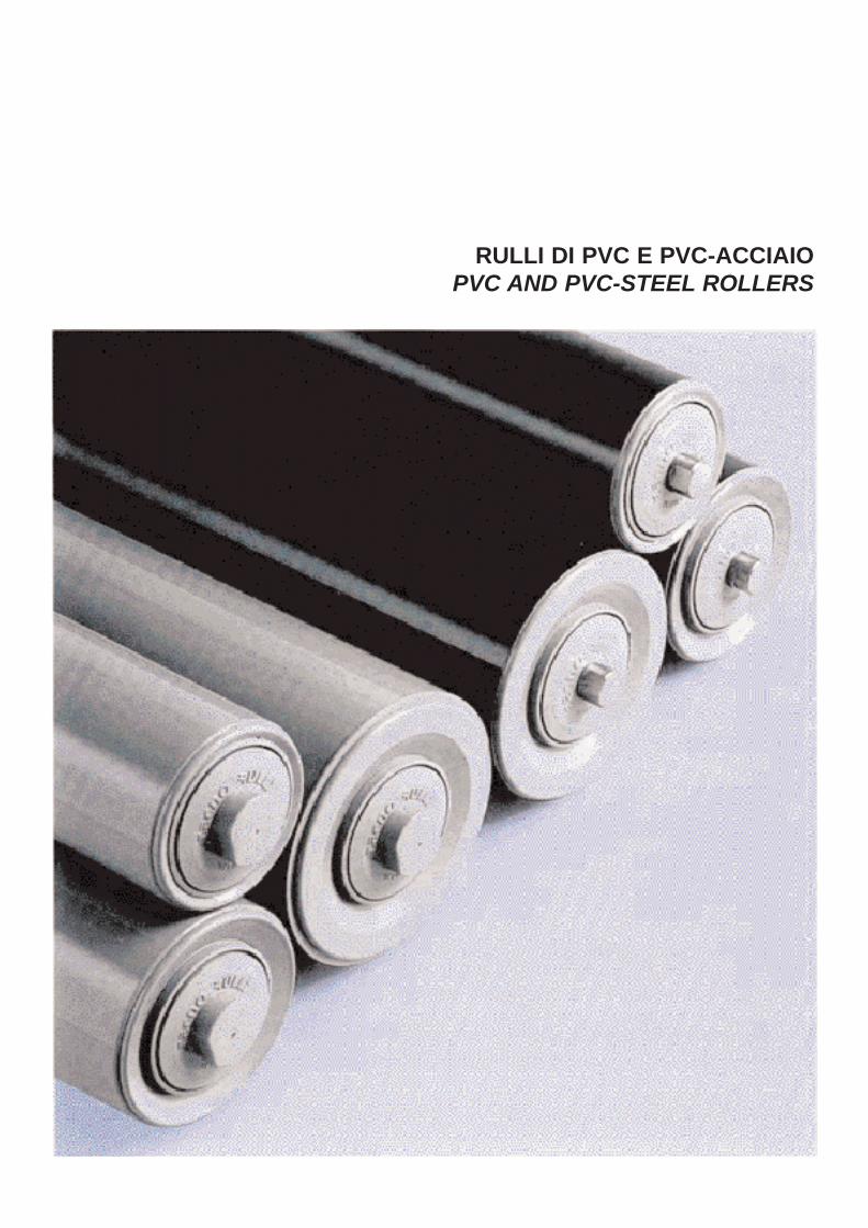
RULLI DI PVC E PVC-ACCIAIOPVC AND PVC-STEEL ROLLERS
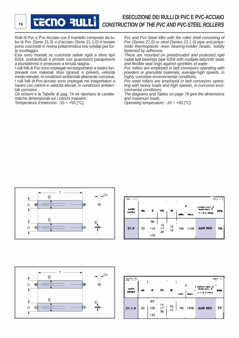
daN 86021.0
daN 86021.1.0
T
D
da
D
da
Ch
M
T
D
da
D
da
Ch
M
74
ESECUZIONE DEI RULLI DI PVC E PVC-ACCIAIO CONSTRUCTION OF THE PVC AND PVC-STEEL ROLLERS
Rulli di Pvc e Pvc-Acciaio con il mantello composto da tu -bo di Pvc (Serie 21.0) o d’acciaio (Serie 21.1.0) e testateporta cuscinetti in resina poliammidica resi solidali per for -te incollaggio.Essi sono montati su cuscinetti radiali rigidi a sfere tipo6204, prelubrificati e protetti con guarnizioni parapolverea plurilabirinto e protezioni a tenuta stagna. I rulli folli di Pvc sono impiegati nei trasportatori a nastro fun-zionanti con materiali sfusi (granuli e polveri), velocitàmedio-elevate, in condizioni ambientali altamente corrosive.I rulli folli di Pvc-acciaio sono impiegati nei trasportatori anastro con carichi e velocità elevati, in condizioni ambien-tali corrosive.Gli schemi e le Tabelle di pag. 74 ne riportano le caratte -ristiche dimensionali ed i carichi massimi. Temperatura d’esercizio: -10 ÷ +50 [°C].
Pvc and Pvc-Steel idler with the roller shell consisting ofPvc (Series 21.0) or steel (Series 21.1.0) pipe and polya-mide thermoplastic resin bearing-holder heads, solidlyfastened by adhesive.These are mounted on prelubricated and protected rigidradial ball bearings type 6204 with multiple-labyrinth sealsand flexible seal rings against sprinkles of water. Pvc rollers are employed in belt conveyors operating withpowders or granulate materials, average-high speeds, inhighly cor rosive environmental conditions. Pvc-steel rollers are employed in belt conveyors opera -ting with heavy loads and high speeds, in corrosive envi-ronmental conditions. The diagrams and Tables on page 74 give the dimensionsand maximum loads. Operating temperature: -10 ÷ +50 [°C].
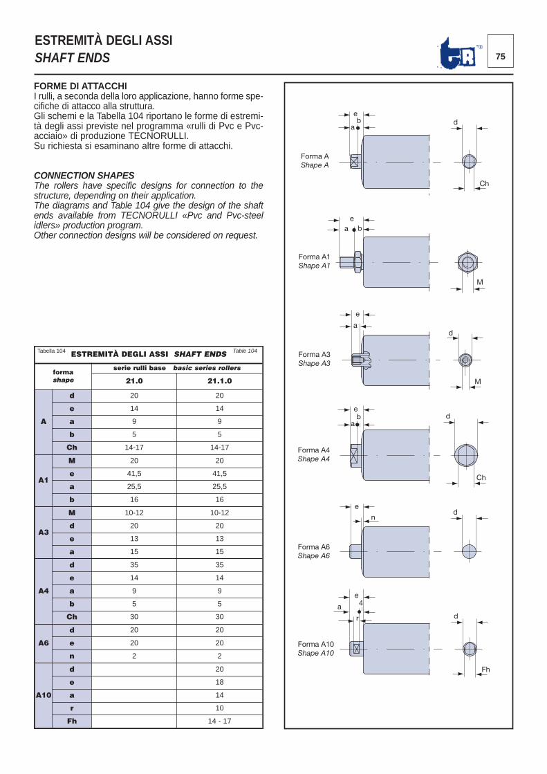
75®
ESTREMITÀ DEGLI ASSISHAFT ENDS
FORME DI ATTACCHII rulli, a seconda della loro applicazione, hanno forme spe -cifiche di attacco alla struttura. Gli schemi e la Tabella 104 riportano le forme di estremi -tà degli assi previste nel programma «rulli di Pvc e Pvc-acciaio» di produzione TECNORULLI. Su richiesta si esaminano altre forme di attacchi.
CONNECTION SHAPESThe rollers have specific designs for connection to thestructure, depending on their application.The diagrams and Table 104 give the design of the shaftends available from TECNORULLI «Pvc and Pvc-steelidlers» production program.Other connection designs will be considered on request.
ESTREMITÀ DEGLI ASSI SHAFT ENDS
formashape
serie rulli base basic series rollers
21.0 21.1.0
A
d 20 20
e 14 14
a 9 9
b 5 5
Ch 14-17 14-17
A1
M 20 20
e 41,5 41,5
a 25,5 25,5
b 16 16
A3
M 10-12 10-12
d 20 20
e 13 13
a 15 15
A4
d 35 35
e 14 14
a 9 9
b 5 5
Ch 30 30
A6
d 20 20
e 20 20
n 2 2
A10
d 20
e 18
a 14
r 10
Fh 14 - 17
Forma A1Shape A1
e a b
M
e
a
M
d
Forma A3Shape A3
e
a b
Forma A4Shape A4
d
Ch
Forma A6Shape A6
n d
Forma A10Shape A10
Forma AShape A
e b
a d
Ch
e
e
a 4
r d
Fh
Tabella 104 Table 104
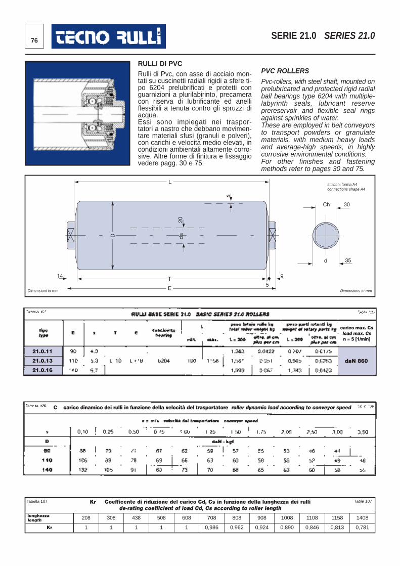
daN 860
21.0.11
21.0.13
21.0.16
76 SERIE 21.0 SERIES 21.0
14
L
D
20
T
E 5
9
s
Ch 30
d 35
da
Dimensioni in mm Dimensions in mm
RULLI DI PVCRulli di Pvc, con asse di acciaio mon -tati su cuscinetti radiali rigidi a sfere ti -po 6204 prelubrificati e protetti conguarnizioni a plurilabirinto, precameracon riserva di lubrificante ed anellifles sibili a tenuta contro gli spruzzi diacqua.Essi sono impiegati nei traspor -tatori a nastro che debbano movimen -tare materiali sfusi (granuli e polveri),con carichi e velocità medio elevati, incondizioni ambientali altamente corro -sive. Altre forme di finitura e fissaggiovedere pagg. 30 e 75.
PVC ROLLERS
Pvc-rollers, with steel shaft, mounted onprelubricated and protected rigid radi alball bearings type 6204 with multiple-labyrinth seals, lubricant reserveprereservoir and flexible seal ringsagainst sprinkles of water.These are employed in belt conveyorsto transport powders or granulatematerials, with medium heavy loadsand average-high speeds, in highlycorrosive environmental conditions. For other finishes and fasteningmethods refer to pages 30 and 75.
Kr Coefficente di riduzione del carico Cd, Cs in funzione della lunghezza dei rullide-rating coefficient of load Cd, Cs according to roller length
lunghezzalength 208 308 438 508 608 708 808 908 1008 1108 1158 1408
Kr 1 1 1 1 1 0,986 0,962 0,924 0,890 0,846 0,813 0,781
Tabella 107 Table 107
carico max. Csload max. Csn = 5 [1/min]
attacchi forma A4connections shape A4
C carico dinamico dei rulli in funzione della velocità del trasportatore roller dynamic load according to conveyor speed
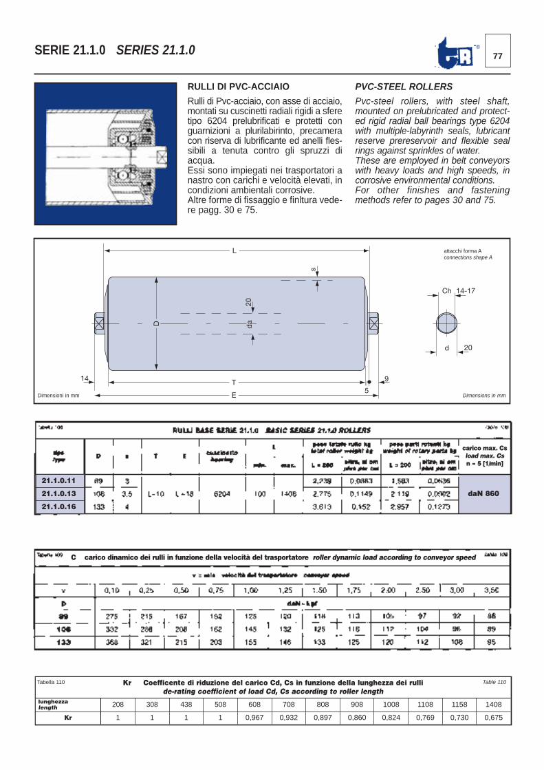
daN 860
77®SERIE 21.1.0 SERIES 21.1.0
14
L
D
20
T
E 5
9
s
da
Ch 14-17
d 20
Dimensioni in mm Dimensions in mm
RULLI DI PVC-ACCIAIO
Rulli di Pvc-acciaio, con asse di acciaio,montati su cuscinetti radiali rigidi a sferetipo 6204 prelubrificati e protetti conguarnizioni a plurilabirinto, precameracon riserva di lubrificante ed anelli fles-sibili a tenuta contro gli spruzzi diacqua.Essi sono impiegati nei trasportatori anastro con carichi e velocità elevati, incondizioni ambientali corrosive.Altre forme di fissaggio e finltura vede-re pagg. 30 e 75.
PVC-STEEL ROLLERS
Pvc-steel rollers, with steel shaft,mounted on prelubricated and protect-ed rigid radial ball bearings type 6204with multiple-labyrinth seals, lubricantreserve prereservoir and flexible sealrings against sprinkles of water.These are employed in belt conveyorswith heavy loads and high speeds, incorrosive environmental conditions. For other finishes and fasteningmethods refer to pages 30 and 75.
Kr Coefficente di riduzione del carico Cd, Cs in funzione della lunghezza dei rullide-rating coefficient of load Cd, Cs according to roller length
lunghezzalength 208 308 438 508 608 708 808 908 1008 1108 1158 1408
Kr 1 1 1 1 0,967 0,932 0,897 0,860 0,824 0,769 0,730 0,675
Tabella 110 Table 110
carico max. Csload max. Csn = 5 [1/min]
attacchi forma Aconnections shape A
C carico dinamico dei rulli in funzione della velocità del trasportatore roller dynamic load according to conveyor speed
21.1.0.11
21.1.0.13
21.1.0.16
78
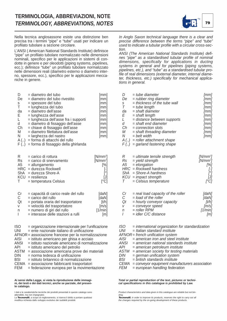
TERMINOLOGIA, ABBREVIAZIONI, NOTETERMINOLOGY, ABBREVIATIONS, NOTES
Nella tecnica anglosassone esiste una distinzione benprecisa tra i termini “pipe” e “tube” usati per indicare unprofilato tubolare a sezione circolare.L’ANSI ( American National Standards Institute) definisce“pipe” un profilato tubolare normalizzato nelle dimensioninominali, specifico per le applicazioni in sistemi di con-dotte in genere e per oleodotti (piping systems, pipelines,ecc.); definisce “tube” un profilato tubolare normalizzatonelle dimensioni reali (diametro esterno o diametro inter-no, spessore, ecc.), specifico per le applicazioni mecca-niche in genere.
D = diametro del tubo [mm]De = diametro del tubo rivestito [mm]s = spessore del tubo [mm]T = lunghezza del tubo [mm]da = diametro dell’asse [mm]E = lunghezza dell’asse [mm]L = lunghezza dell’asse fra i supporti [mm]d = diametro di fissaggio dell’asse [mm]Ch = chiave di fissaggio dell’asse [mm]M = diametro filettatura dell’asse [mm]N = larghezza del nastro [mm]A (..) = forma di attacchi del rullo F (..) = forma di fissaggio della ghirlanda
R = carico di rottura [N/mm2]Rs = carico di snervamento [N/mm2]A5 = allungamento [%]HRC = durezza Rockwell [-]ShA = durezza Shore-A [°]KCU = resilienza [J]T = temperatura Celsius [°C]
Cr = capacità di carico reale del rullo [daN]C = carico del rullo [daN]Qt = portata oraria del trasportatore [t/h]v = velocità del trasportatore [m/s]n = numero di giri del rullo [1/min]I = interasse delle stazioni a rulli [m]
ISO = organizzazione internazionale per l’unificazioneUNI = ente nazionale italiano di unificazioneAFNOR= associazione francese per la normalizzazioneAISI = istituto americano per ghisa e acciaioANSI = istituto nazionale americano di normalizzazioneAPI = istituto americano del petrolioASTM = associazione americana prove dei materialiDIN = norma tedesca di unificazioneBSI = istituto britannico di normalizzazioneCEMA = associazione fabbricanti trasportatoriFEM = federazione europea per la movimentazione
In Anglo Saxon technical language there is a clear andprecise difference between the terms “pipe” and “tube”used to indicate a tubular profile with a circular cross-sec-tion.ANSI (The American National Standards Institute) defi-nes “pipe” as a standardised tubular profile of nominaldimensions, specifically for applications in ductingsystems in general and for pipelines (piping systems,pipelines, etc.), and “tube” as a standardised tubular pro-file of real dimensions (external diameter, internal diame-ter, thickness, etc.) specifically for mechanical applica-tions in general.
D = tube diameter [mm]De = rubber ring diameter [mm]s = thickness of the tube wall [mm]T = tube length [mm]da = shaft diameter [mm]E = shaft length [mm]L = distance between supports [mm]d = shaft end diameter [mm]Ch = connection slots [mm]M = shaft threading diameter [mm]N = belt width [mm]A (..) = roller attachment shapeF (..) = garland fastening shape
R = ultimate tensile strength [N/mm2]Rs = yield strength [N/mm2]A5 = elongation [%]HRC = Rockwell hardness [-]ShA = Shore-A hardness [°]KCU = impact strength [J]T = Celsius temperature [°C]
Cr = real load capacity of the roller [daN]C = load of the roller [daN]Qt = hourly conveyor capacity [t/h]v = conveyor speed [m/s]n = roller RPM [1/min]I = idler C/C distance [m]
ISO = international organization for standardizationUNI = Italian standard instituteAFNOR= french unification systemAISI = american iron and steel instituteANSI = american national standards instituteAPI = american petroleum instituteASTM = american society for testing materialsDIN = german unification systemBSI = british standards instituteCEMA = conveyor equipment manufacturers associationFEM = european handling federation
Ai sensi della Legge, si vieta la riproduzione delle immagi-ni, dei testi e dei dati tecnici, anche se parziale, del presen-te catalogo.
I dati e le caratteristiche tecniche dei prodotti presentati in questo catalogo sonoattendibili, ma non impegnativi.La Tecnorulli, a scopo di miglioramento, si riserva il diritto a portare qualsiasimodifica richiesta dallo sviluppo evolutivo dei suddetti prodotti.
Total or partial reproduction of the text, pictures or techni-cal specifications in this catalogue is prohibited by Law.
Product characteristics and data given in this catalogue are reliable but not bin-ding.Tecnorulli, in order to improve its products, reserves the right to carry out allthe changes required by the on-going development of these products.
79 ®
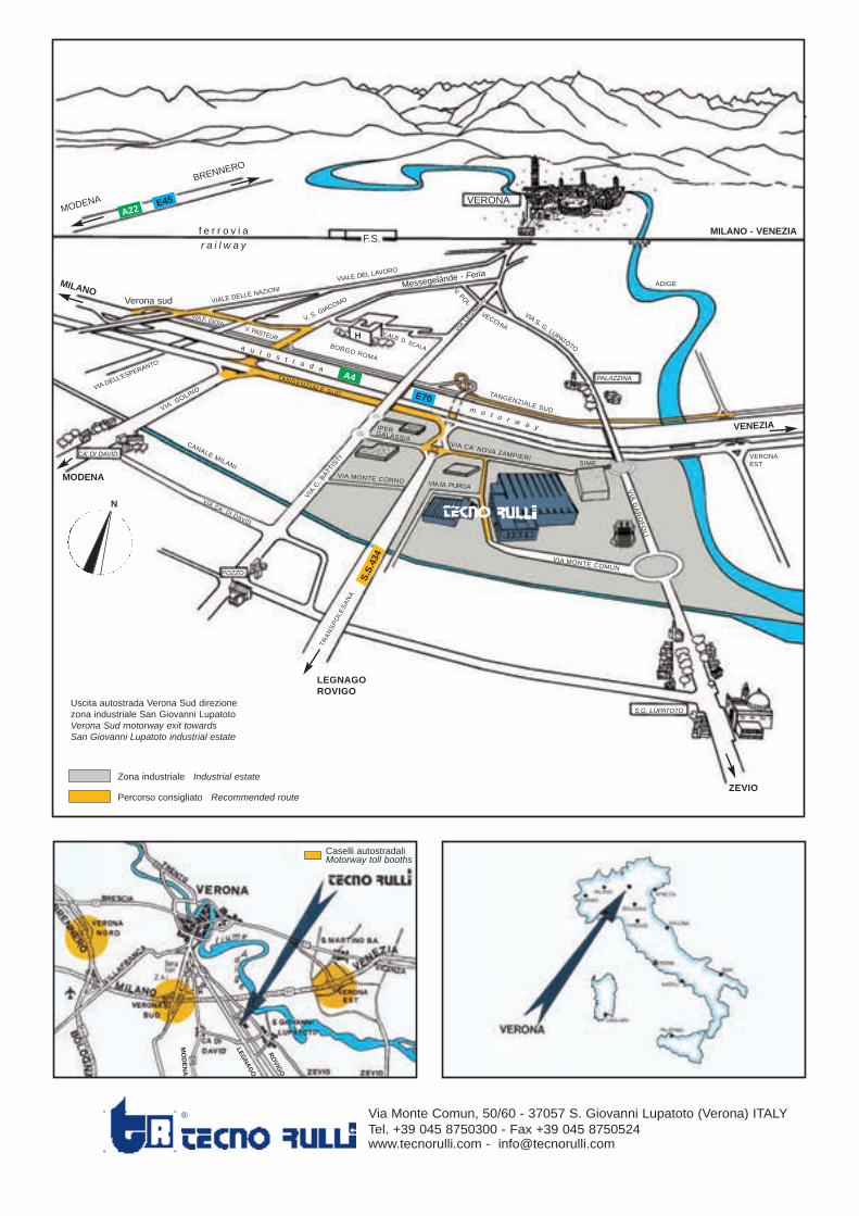
80
Uscita autostrada Verona Sud direzionezona industriale San Giovanni LupatotoVerona Sud motorway exit towardsSan Giovanni Lupatoto industrial estate
Zona industriale Industrial estate
Percorso consigliato Recommended route
VERONA
f e r r o v i ar a i l w a y
MODENA
BRENNERO
F.S.
MILANO
MILANO - VENEZIA
Verona sud VIALE DELLE N
AZIONI
VIA DE
LL’ESPE
RANTO
VIA GOLINO
CANALE MILANI
VIA C. BATTISTI
BORGO ROMA
VIA M. PURGA
TRANSPOLESANA
TANGENZIALE SUD TANGENZIALE SUD
VIA CA’ NOVA ZAMPIERI
IPERGALASSIA
VIA MONTE COMUN
VIA GAROFOLI
SIME
VIA CA’ DI DAVID
VIALE DEL LAVO
RO
VIA S. G. LUPATOTO
ADIGE
VERONAEST
ZEVIO
PALAZZINA
S.G. LUPATOTO
POZZO
CA’ DI DAVID
a u t o s t r a d a
m o t o r w a y
V. S. GIACOMO
H V.ALB. D. SCALA
V. POL
VECCHIA
VIA LEGNAGO
V. PASTEUR
VIA F. GIOIA
A22E45
A4
E70
S.S.
434
VENEZIA
MODENA
LEGNAGOROVIGO
N
VIA MONTE CORNO
Caselli autostradaliMotorway toll booths
LEGN
AG
O
RO
VIGO
MO
DE
NA
Messegelände - Fe
ria
® Via Monte Comun, 50/60 - 37057 S. Giovanni Lupatoto (Verona) ITALYTel. +39 045 8750300 - Fax +39 045 8750524www.tecnorulli.com - [email protected]