Page 1
80548_GPC 400-600A - MODBUS MEMORY MAP V.2.10 – 12/2020
1
GPCMAPPA DI MEMORIA MODBUS / MODBUS MEMORY MAP
INTRODUZIONE / INTRODUCTION ����������������������������������������������������������������������������������������������������������������������������������������������������������������������������������������������������������������������������������������������������������������������������������������������2MODALITÀ DI ACCESSO / ACCESS MODE ���������������������������������������������������������������������������������������������������������������������������������������������������������������������������������������������������������������������������������������������������������������������������������3MAPPA DI ZONA (accesso a 16bit) / ZONE MAP (16bit access) ��������������������������������������������������������������������������������������������������������������������������������������������������������������������������������������������������������������������������������������������������4MAPPA DI ZONA (accesso a 1bit) / ZONE MAP (1bit access) ����������������������������������������������������������������������������������������������������������������������������������������������������������������������������������������������������������������������������������������������������31MAPPA PERSONALIZZABILE (accesso a 16bit) / CUSTOM MAP (16bit access) ���������������������������������������������������������������������������������������������������������������������������������������������������������������������������������������������������������������������34DESCRIZIONE DATI ENUMERATIVI / ENUMERATED DATA DESCRIPTION ���������������������������������������������������������������������������������������������������������������������������������������������������������������������������������������������������������������������������45DESCRIZIONE DATI A BIT / BIT DATA DESCRIPTION ��������������������������������������������������������������������������������������������������������������������������������������������������������������������������������������������������������������������������������������������������������������56TABELLA DELLE ECCEZIONI / TABLE OF EXCEPTIONS ���������������������������������������������������������������������������������������������������������������������������������������������������������������������������������������������������������������������������������������������������������61TABELLA DELL’ORDINE DI SCRITTURA / TABLE OF WRITE ORDER �������������������������������������������������������������������������������������������������������������������������������������������������������������������������������������������������������������������������������������62
Page 2
80548_GPC 400-600A - MODBUS MEMORY MAP V.2.10 – 12/2020
2
INTRODUZIONE / INTRODUCTION
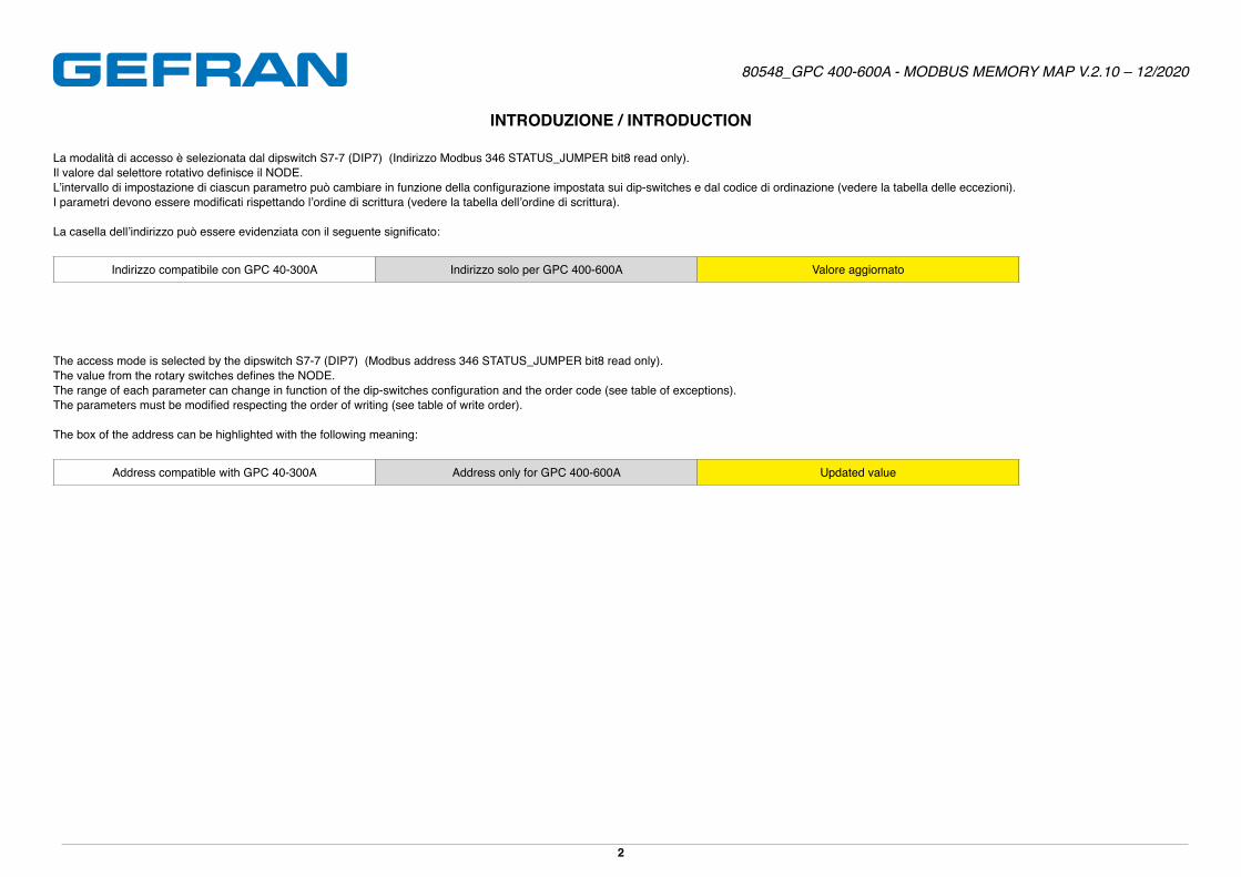
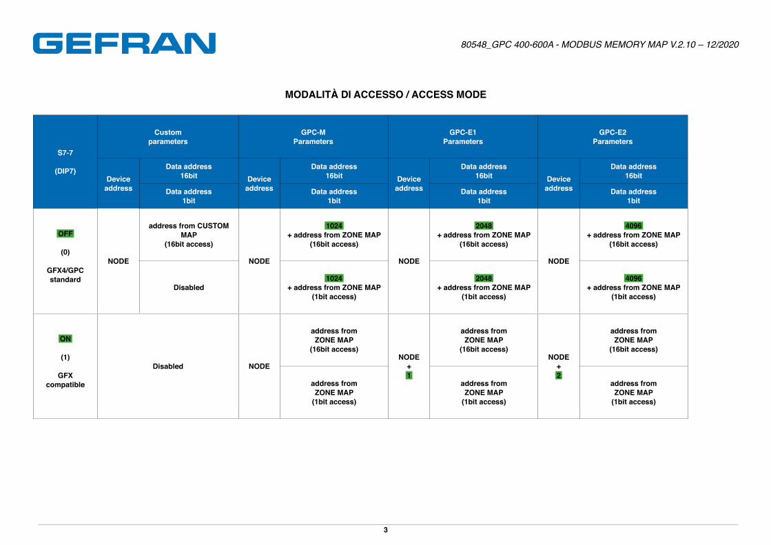
La modalità di accesso è selezionata dal dipswitch S7-7 (DIP7) (Indirizzo Modbus 346 STATUS_JUMPER bit8 read only)�Il valore dal selettore rotativo definisce il NODE.L’intervallo di impostazione di ciascun parametro può cambiare in funzione della configurazione impostata sui dip-switches e dal codice di ordinazione (vedere la tabella delle eccezioni).I parametri devono essere modificati rispettando l’ordine di scrittura (vedere la tabella dell’ordine di scrittura).
La casella dell’indirizzo può essere evidenziata con il seguente significato:
Indirizzo compatibile con GPC 40-300A Indirizzo solo per GPC 400-600A Valore aggiornato
The access mode is selected by the dipswitch S7-7 (DIP7) (Modbus address 346 STATUS_JUMPER bit8 read only)�The value from the rotary switches defines the NODE.The range of each parameter can change in function of the dip-switches configuration and the order code (see table of exceptions).The parameters must be modified respecting the order of writing (see table of write order).
The box of the address can be highlighted with the following meaning:
Address compatible with GPC 40-300A Address only for GPC 400-600A Updated value
Page 3
80548_GPC 400-600A - MODBUS MEMORY MAP V.2.10 – 12/2020
3
MODALITÀ DI ACCESSO / ACCESS MODE
S7-7
(DIP7)
Customparameters
GPC-MParameters
GPC-E1Parameters
GPC-E2Parameters
Deviceaddress
Data address16bit Device
address
Data address16bit Device
address
Data address16bit Device
address
Data address16bit
Data address1bit
Data address1bit
Data address1bit
Data address1bit
OFF
(0)
GFX4/GPCstandard
NODE
address from CUSTOM MAP
(16bit access)
NODE
1024+ address from ZONE MAP
(16bit access)
NODE
2048+ address from ZONE MAP
(16bit access)
NODE
4096+ address from ZONE MAP
(16bit access)
Disabled1024
+ address from ZONE MAP(1bit access)
2048+ address from ZONE MAP
(1bit access)
4096+ address from ZONE MAP
(1bit access)
ON
(1)
GFXcompatible
Disabled NODE
address fromZONE MAP
(16bit access)NODE
+ 1
address fromZONE MAP
(16bit access)NODE
+ 2
address fromZONE MAP
(16bit access)
address fromZONE MAP
(1bit access)
address fromZONE MAP
(1bit access)
address fromZONE MAP
(1bit access)
Page 4
80548_GPC 400-600A - MODBUS MEMORY MAP V.2.10 – 12/2020
4
MAPPA DI ZONA (accesso a 16bit) / ZONE MAP (16bit access)
IndirizzoAddress
SiglaItem Descrizione Description R/W Min Max Punto Decimale
Decimal pointTipo (1)
Type (1) Default
Unità di misuraUnit of
measure
GlobaleGlobal
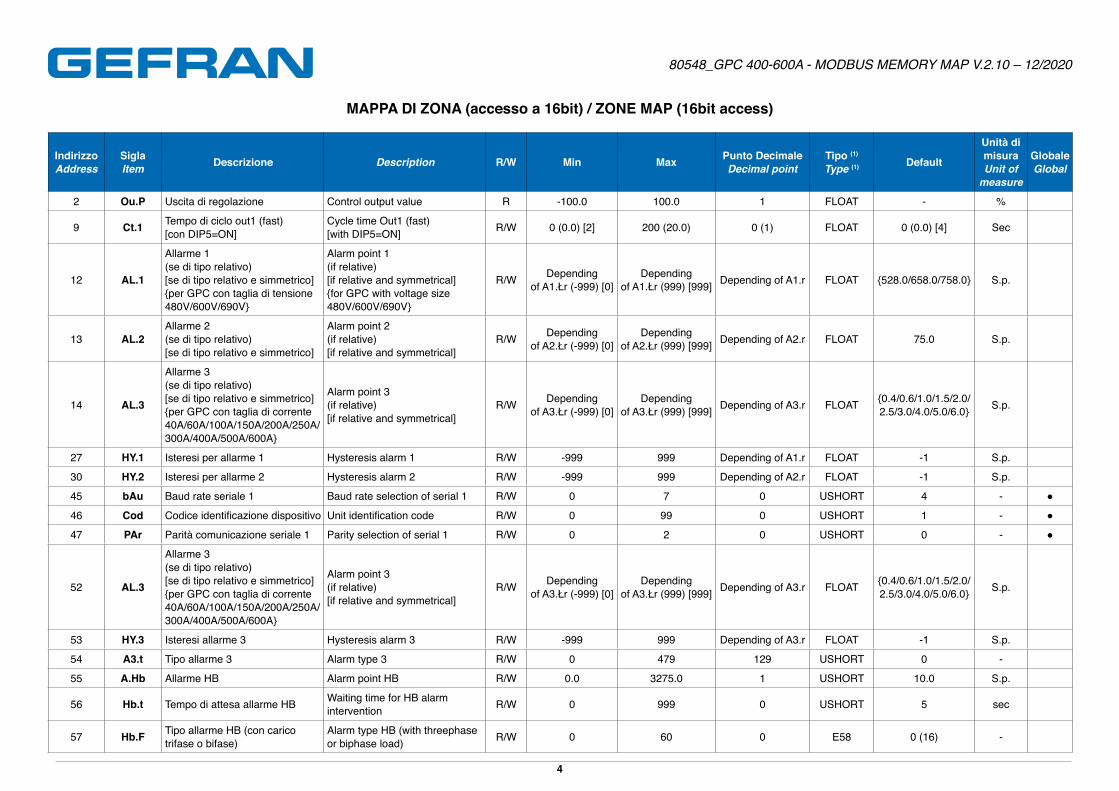
2 Ou.P Uscita di regolazione Control output value R -100�0 100�0 1 FLOAT - %
9 Ct.1 Tempo di ciclo out1 (fast) [con DIP5=ON]
Cycle time Out1 (fast) [with DIP5=ON] R/W 0 (0�0) [2] 200 (20�0) 0 (1) FLOAT 0 (0�0) [4] Sec
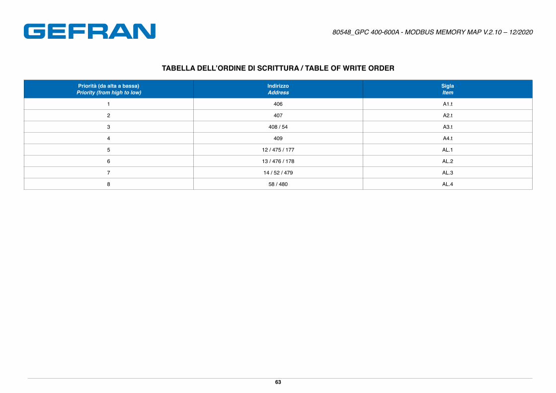
12 AL.1
Allarme 1(se di tipo relativo)[se di tipo relativo e simmetrico]{per GPC con taglia di tensione 480V/600V/690V}
Alarm point 1(if relative)[if relative and symmetrical]{for GPC with voltage size 480V/600V/690V}
R/W Dependingof A1.Łr (-999) [0]
Dependingof A1.Łr (999) [999] Depending of A1.r FLOAT {528�0/658�0/758�0} S�p�
13 AL.2Allarme 2 (se di tipo relativo) [se di tipo relativo e simmetrico]
Alarm point 2 (if relative) [if relative and symmetrical]
R/W Dependingof A2.Łr (-999) [0]
Dependingof A2.Łr (999) [999] Depending of A2.r FLOAT 75�0 S�p�
14 AL.3
Allarme 3(se di tipo relativo)[se di tipo relativo e simmetrico]{per GPC con taglia di corrente 40A/60A/100A/150A/200A/250A/300A/400A/500A/600A}
Alarm point 3(if relative)[if relative and symmetrical]
R/W Dependingof A3.Łr (-999) [0]
Dependingof A3.Łr (999) [999] Depending of A3.r FLOAT {0�4/0�6/1�0/1�5/2�0/
2�5/3�0/4�0/5�0/6�0} S�p�
27 HY.1 Isteresi per allarme 1 Hysteresis alarm 1 R/W -999 999 Depending of A1.r FLOAT -1 S�p�
30 HY.2 Isteresi per allarme 2 Hysteresis alarm 2 R/W -999 999 Depending of A2.r FLOAT -1 S�p�
45 bAu Baud rate seriale 1 Baud rate selection of serial 1 R/W 0 7 0 USHORT 4 - ●
46 Cod Codice identificazione dispositivo Unit identification code R/W 0 99 0 USHORT 1 - ●
47 PAr Parità comunicazione seriale 1 Parity selection of serial 1 R/W 0 2 0 USHORT 0 - ●
52 AL.3
Allarme 3(se di tipo relativo)[se di tipo relativo e simmetrico]{per GPC con taglia di corrente 40A/60A/100A/150A/200A/250A/300A/400A/500A/600A}
Alarm point 3(if relative)[if relative and symmetrical]
R/W Dependingof A3.Łr (-999) [0]
Dependingof A3.Łr (999) [999] Depending of A3.r FLOAT {0�4/0�6/1�0/1�5/2�0/
2�5/3�0/4�0/5�0/6�0} S�p�
53 HY.3 Isteresi allarme 3 Hysteresis alarm 3 R/W -999 999 Depending of A3.r FLOAT -1 S�p�
54 A3.t Tipo allarme 3 Alarm type 3 R/W 0 479 129 USHORT 0 -
55 A.Hb Allarme HB Alarm point HB R/W 0�0 3275�0 1 USHORT 10�0 S�p�
56 Hb.t Tempo di attesa allarme HB Waiting time for HB alarm intervention R/W 0 999 0 USHORT 5 sec
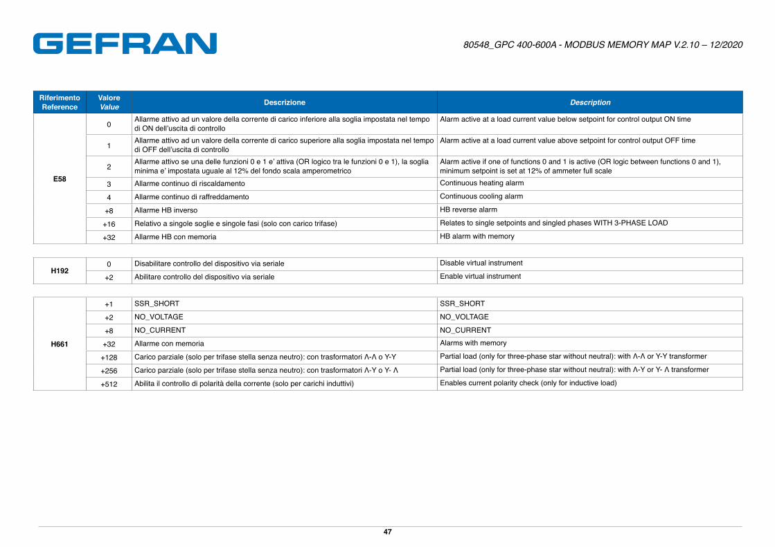
57 Hb.F Tipo allarme HB (con carico trifase o bifase)
Alarm type HB (with threephase or biphase load) R/W 0 60 0 E58 0 (16) -
Page 5
80548_GPC 400-600A - MODBUS MEMORY MAP V.2.10 – 12/2020
5
IndirizzoAddress
SiglaItem Descrizione Description R/W Min Max Punto Decimale
Decimal pointTipo (1)
Type (1) Default
Unità di misuraUnit of
measure
GlobaleGlobal
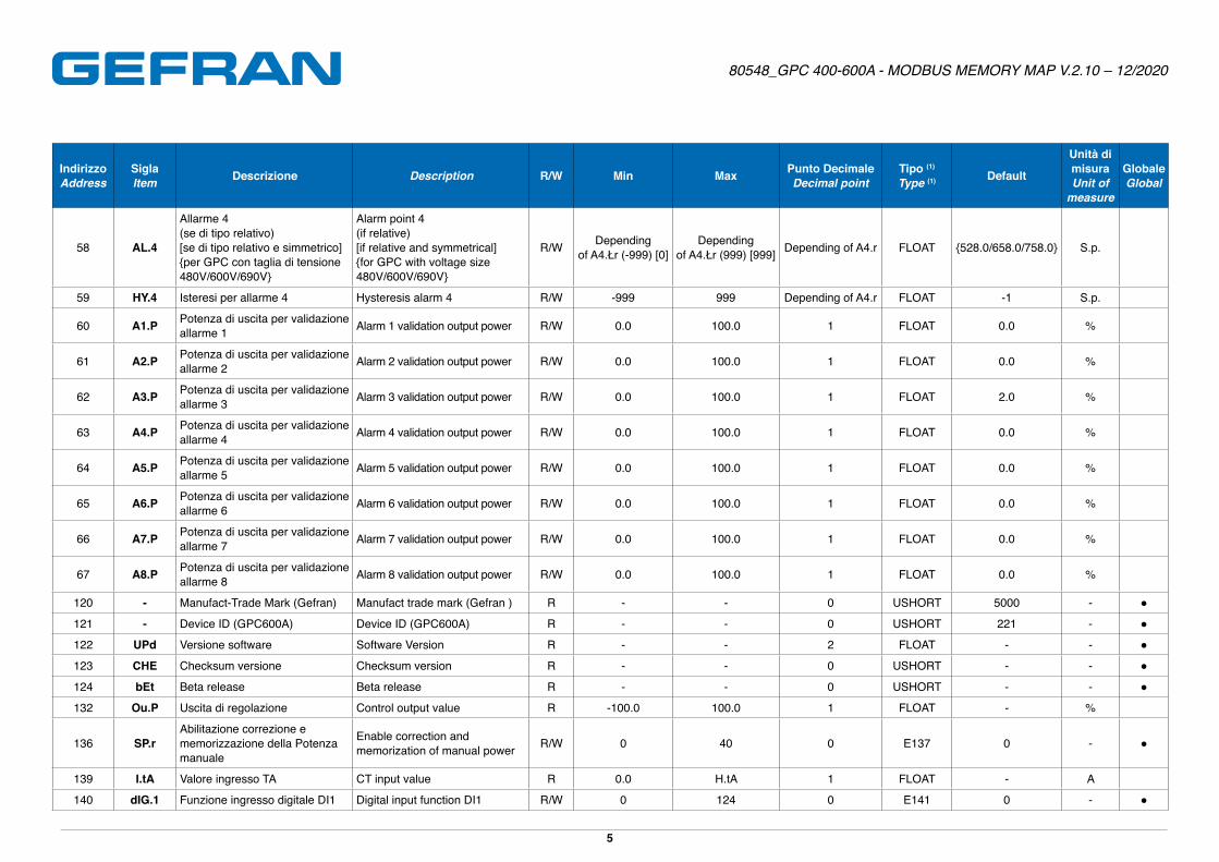
58 AL.4
Allarme 4(se di tipo relativo)[se di tipo relativo e simmetrico]{per GPC con taglia di tensione 480V/600V/690V}
Alarm point 4(if relative)[if relative and symmetrical]{for GPC with voltage size 480V/600V/690V}
R/W Dependingof A4.Łr (-999) [0]
Dependingof A4.Łr (999) [999] Depending of A4.r FLOAT {528�0/658�0/758�0} S�p�
59 HY.4 Isteresi per allarme 4 Hysteresis alarm 4 R/W -999 999 Depending of A4.r FLOAT -1 S�p�
60 A1.P Potenza di uscita per validazione allarme 1 Alarm 1 validation output power R/W 0�0 100�0 1 FLOAT 0�0 %
61 A2.P Potenza di uscita per validazione allarme 2 Alarm 2 validation output power R/W 0�0 100�0 1 FLOAT 0�0 %
62 A3.P Potenza di uscita per validazione allarme 3 Alarm 3 validation output power R/W 0�0 100�0 1 FLOAT 2�0 %
63 A4.P Potenza di uscita per validazione allarme 4 Alarm 4 validation output power R/W 0�0 100�0 1 FLOAT 0�0 %
64 A5.P Potenza di uscita per validazione allarme 5 Alarm 5 validation output power R/W 0�0 100�0 1 FLOAT 0�0 %
65 A6.P Potenza di uscita per validazione allarme 6 Alarm 6 validation output power R/W 0�0 100�0 1 FLOAT 0�0 %
66 A7.P Potenza di uscita per validazione allarme 7 Alarm 7 validation output power R/W 0�0 100�0 1 FLOAT 0�0 %
67 A8.P Potenza di uscita per validazione allarme 8 Alarm 8 validation output power R/W 0�0 100�0 1 FLOAT 0�0 %
120 - Manufact-Trade Mark (Gefran) Manufact trade mark (Gefran ) R - - 0 USHORT 5000 - ●
121 - Device ID (GPC600A) Device ID (GPC600A) R - - 0 USHORT 221 - ●
122 UPd Versione software Software Version R - - 2 FLOAT - - ●
123 CHE Checksum versione Checksum version R - - 0 USHORT - - ●
124 bEt Beta release Beta release R - - 0 USHORT - - ●
132 Ou.P Uscita di regolazione Control output value R -100�0 100�0 1 FLOAT - %
136 SP.rAbilitazione correzione e memorizzazione della Potenza manuale
Enable correction and memorization of manual power R/W 0 40 0 E137 0 - ●
139 I.tA Valore ingresso TA CT input value R 0�0 H�tA 1 FLOAT - A
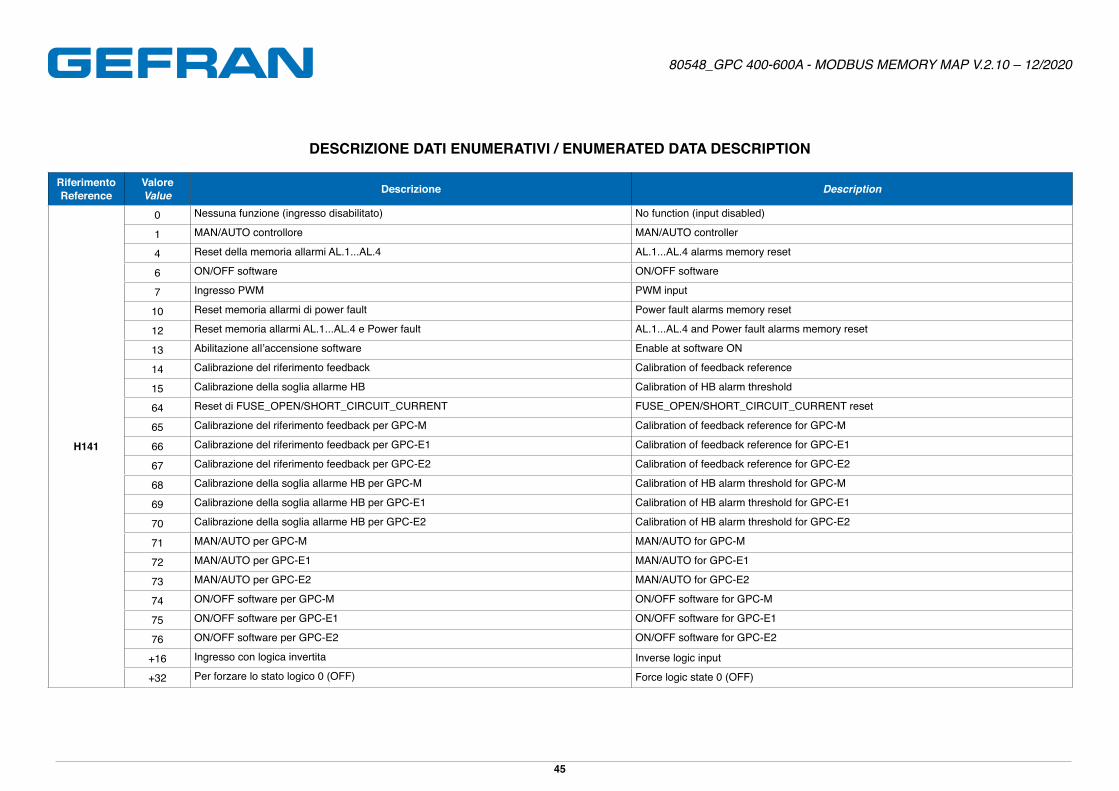
140 dIG.1 Funzione ingresso digitale DI1 Digital input function DI1 R/W 0 124 0 E141 0 - ●
Page 6
80548_GPC 400-600A - MODBUS MEMORY MAP V.2.10 – 12/2020
6
IndirizzoAddress
SiglaItem Descrizione Description R/W Min Max Punto Decimale
Decimal pointTipo (1)
Type (1) Default
Unità di misuraUnit of
measure
GlobaleGlobal
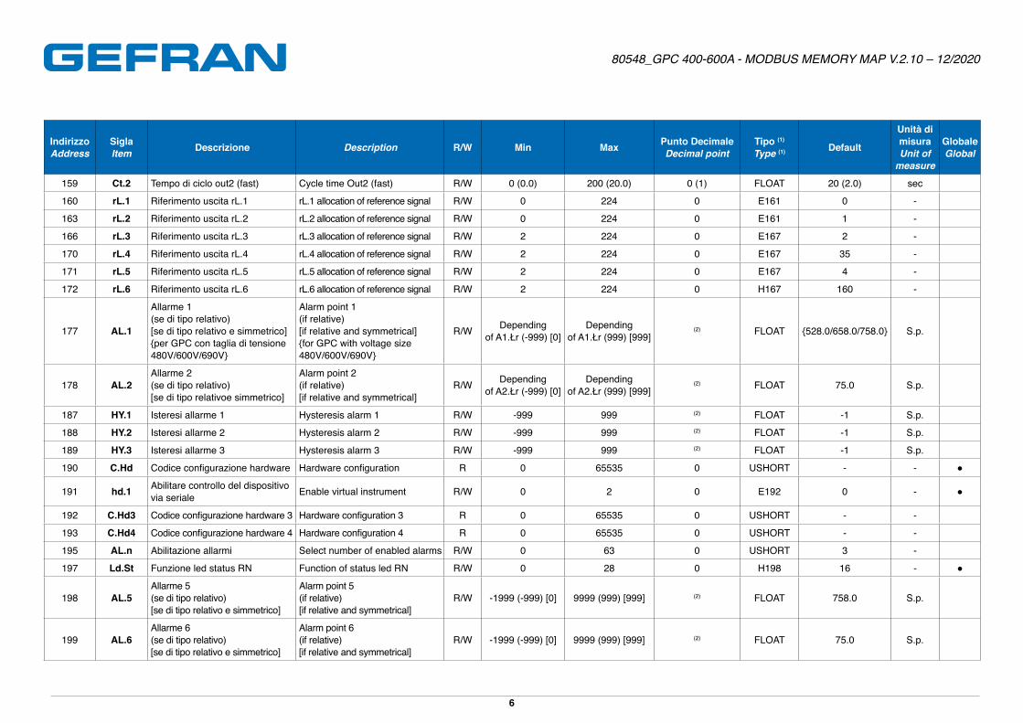
159 Ct.2 Tempo di ciclo out2 (fast) Cycle time Out2 (fast) R/W 0 (0�0) 200 (20�0) 0 (1) FLOAT 20 (2�0) sec
160 rL.1 Riferimento uscita rL.1 rL.1 allocation of reference signal R/W 0 224 0 E161 0 -
163 rL.2 Riferimento uscita rL.2 rL.2 allocation of reference signal R/W 0 224 0 E161 1 -
166 rL.3 Riferimento uscita rL.3 rL.3 allocation of reference signal R/W 2 224 0 E167 2 -
170 rL.4 Riferimento uscita rL.4 rL.4 allocation of reference signal R/W 2 224 0 E167 35 -
171 rL.5 Riferimento uscita rL.5 rL.5 allocation of reference signal R/W 2 224 0 E167 4 -
172 rL.6 Riferimento uscita rL.6 rL.6 allocation of reference signal R/W 2 224 0 H167 160 -
177 AL.1
Allarme 1(se di tipo relativo)[se di tipo relativo e simmetrico]{per GPC con taglia di tensione 480V/600V/690V}
Alarm point 1(if relative)[if relative and symmetrical]{for GPC with voltage size 480V/600V/690V}
R/W Dependingof A1.Łr (-999) [0]
Dependingof A1.Łr (999) [999]
(2) FLOAT {528�0/658�0/758�0} S�p�
178 AL.2Allarme 2 (se di tipo relativo)[se di tipo relativoe simmetrico]
Alarm point 2(if relative)[if relative and symmetrical]
R/W Dependingof A2.Łr (-999) [0]
Dependingof A2.Łr (999) [999]
(2) FLOAT 75�0 S�p�
187 HY.1 Isteresi allarme 1 Hysteresis alarm 1 R/W -999 999 (2) FLOAT -1 S�p�
188 HY.2 Isteresi allarme 2 Hysteresis alarm 2 R/W -999 999 (2) FLOAT -1 S�p�
189 HY.3 Isteresi allarme 3 Hysteresis alarm 3 R/W -999 999 (2) FLOAT -1 S�p�
190 C.Hd Codice configurazione hardware Hardware configuration R 0 65535 0 USHORT - - ●
191 hd.1 Abilitare controllo del dispositivo via seriale Enable virtual instrument R/W 0 2 0 E192 0 - ●
192 C.Hd3 Codice configurazione hardware 3 Hardware configuration 3 R 0 65535 0 USHORT - -
193 C.Hd4 Codice configurazione hardware 4 Hardware configuration 4 R 0 65535 0 USHORT - -
195 AL.n Abilitazione allarmi Select number of enabled alarms R/W 0 63 0 USHORT 3 -
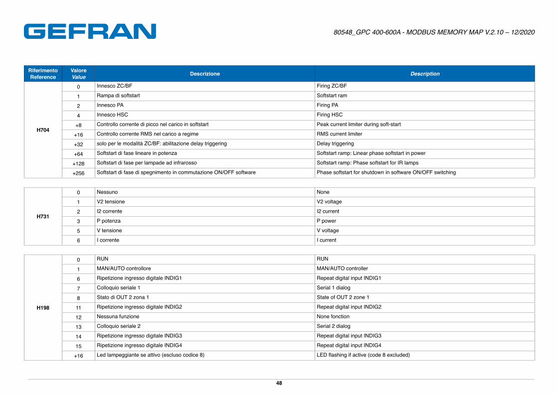
197 Ld.St Funzione led status RN Function of status led RN R/W 0 28 0 H198 16 - ●
198 AL.5Allarme 5(se di tipo relativo)[se di tipo relativo e simmetrico]
Alarm point 5(if relative)[if relative and symmetrical]
R/W -1999 (-999) [0] 9999 (999) [999] (2) FLOAT 758�0 S�p�
199 AL.6Allarme 6(se di tipo relativo)[se di tipo relativo e simmetrico]
Alarm point 6(if relative)[if relative and symmetrical]
R/W -1999 (-999) [0] 9999 (999) [999] (2) FLOAT 75�0 S�p�
Page 7
80548_GPC 400-600A - MODBUS MEMORY MAP V.2.10 – 12/2020
7
IndirizzoAddress
SiglaItem Descrizione Description R/W Min Max Punto Decimale
Decimal pointTipo (1)
Type (1) Default
Unità di misuraUnit of
measure
GlobaleGlobal
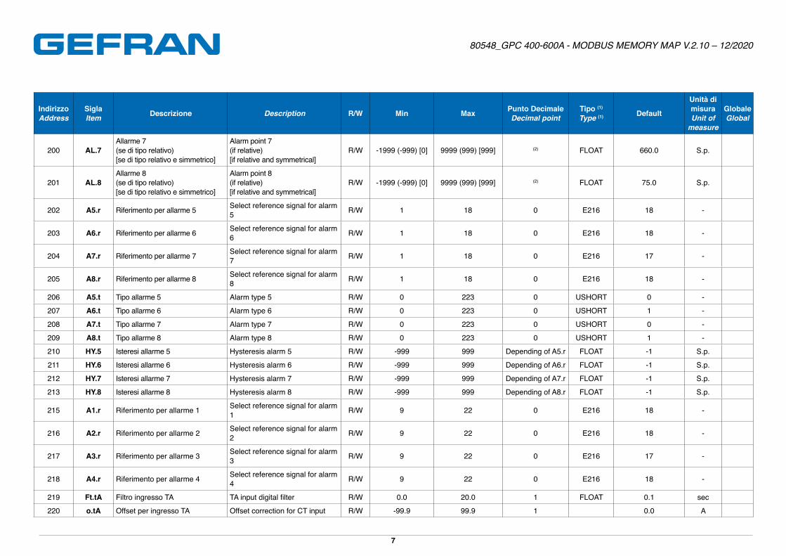
200 AL.7Allarme 7(se di tipo relativo)[se di tipo relativo e simmetrico]
Alarm point 7(if relative)[if relative and symmetrical]
R/W -1999 (-999) [0] 9999 (999) [999] (2) FLOAT 660�0 S�p�
201 AL.8Allarme 8(se di tipo relativo)[se di tipo relativo e simmetrico]
Alarm point 8(if relative)[if relative and symmetrical]
R/W -1999 (-999) [0] 9999 (999) [999] (2) FLOAT 75�0 S�p�
202 A5.r Riferimento per allarme 5 Select reference signal for alarm 5 R/W 1 18 0 E216 18 -
203 A6.r Riferimento per allarme 6 Select reference signal for alarm 6 R/W 1 18 0 E216 18 -
204 A7.r Riferimento per allarme 7 Select reference signal for alarm 7 R/W 1 18 0 E216 17 -
205 A8.r Riferimento per allarme 8 Select reference signal for alarm 8 R/W 1 18 0 E216 18 -
206 A5.t Tipo allarme 5 Alarm type 5 R/W 0 223 0 USHORT 0 -
207 A6.t Tipo allarme 6 Alarm type 6 R/W 0 223 0 USHORT 1 -
208 A7.t Tipo allarme 7 Alarm type 7 R/W 0 223 0 USHORT 0 -
209 A8.t Tipo allarme 8 Alarm type 8 R/W 0 223 0 USHORT 1 -
210 HY.5 Isteresi allarme 5 Hysteresis alarm 5 R/W -999 999 Depending of A5.r FLOAT -1 S�p�
211 HY.6 Isteresi allarme 6 Hysteresis alarm 6 R/W -999 999 Depending of A6.r FLOAT -1 S�p�
212 HY.7 Isteresi allarme 7 Hysteresis alarm 7 R/W -999 999 Depending of A7.r FLOAT -1 S�p�
213 HY.8 Isteresi allarme 8 Hysteresis alarm 8 R/W -999 999 Depending of A8.r FLOAT -1 S�p�
215 A1.r Riferimento per allarme 1 Select reference signal for alarm 1 R/W 9 22 0 E216 18 -
216 A2.r Riferimento per allarme 2 Select reference signal for alarm 2 R/W 9 22 0 E216 18 -
217 A3.r Riferimento per allarme 3 Select reference signal for alarm 3 R/W 9 22 0 E216 17 -
218 A4.r Riferimento per allarme 4 Select reference signal for alarm 4 R/W 9 22 0 E216 18 -
219 Ft.tA Filtro ingresso TA TA input digital filter R/W 0�0 20�0 1 FLOAT 0�1 sec
220 o.tA Offset per ingresso TA Offset correction for CT input R/W -99�9 99�9 1 0�0 A
Page 8
80548_GPC 400-600A - MODBUS MEMORY MAP V.2.10 – 12/2020
8
IndirizzoAddress
SiglaItem Descrizione Description R/W Min Max Punto Decimale
Decimal pointTipo (1)
Type (1) Default
Unità di misuraUnit of
measure
GlobaleGlobal
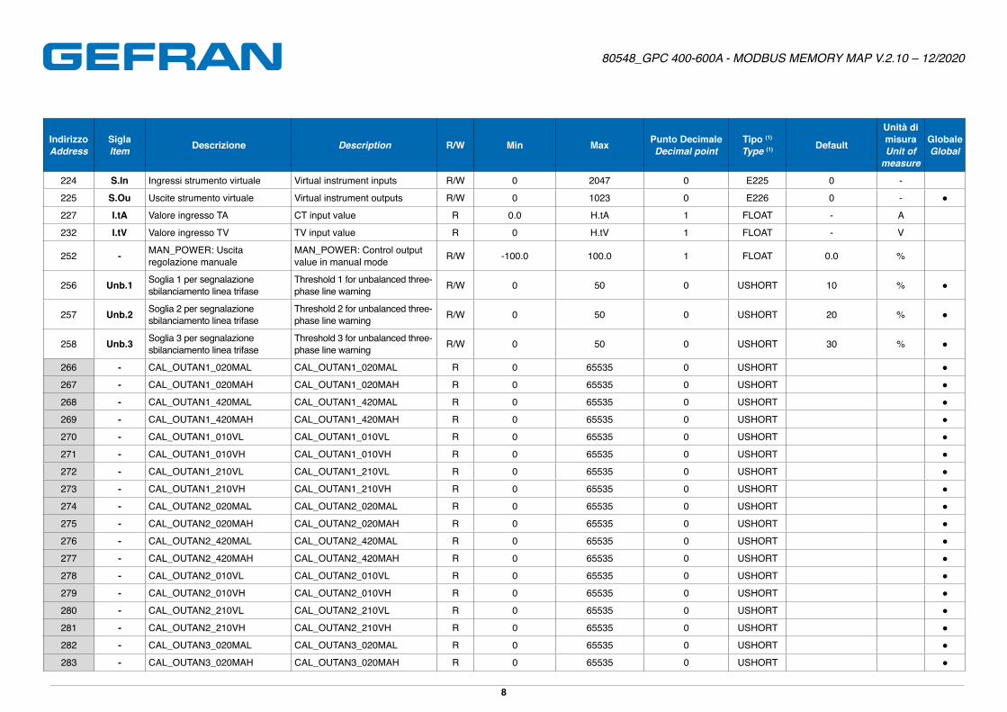
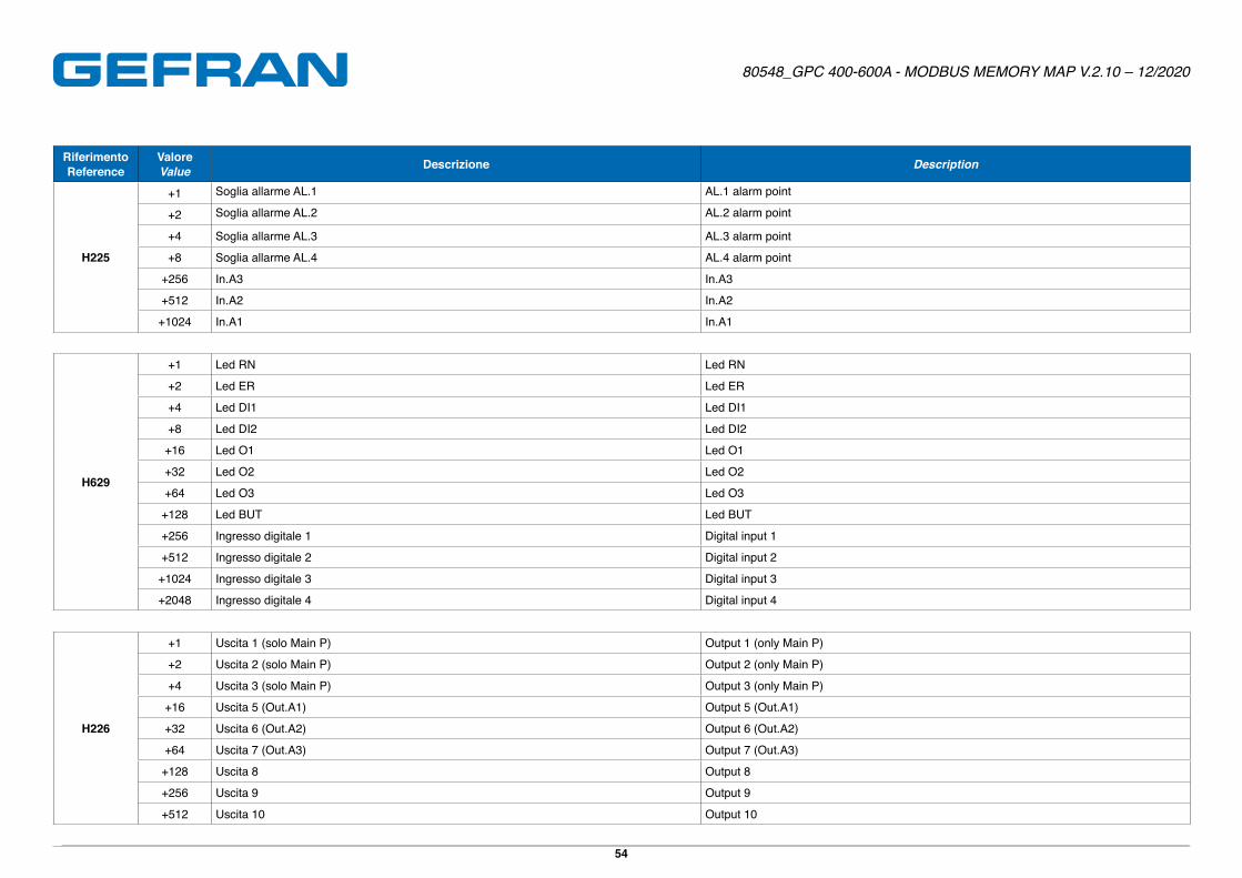
224 S.In Ingressi strumento virtuale Virtual instrument inputs R/W 0 2047 0 E225 0 -
225 S.Ou Uscite strumento virtuale Virtual instrument outputs R/W 0 1023 0 E226 0 - ●
227 I.tA Valore ingresso TA CT input value R 0�0 H�tA 1 FLOAT - A
232 I.tV Valore ingresso TV TV input value R 0 H�tV 1 FLOAT - V
252 - MAN_POWER: Uscita regolazione manuale
MAN_POWER: Control output value in manual mode R/W -100�0 100�0 1 FLOAT 0�0 %
256 Unb.1 Soglia 1 per segnalazione sbilanciamento linea trifase
Threshold 1 for unbalanced three-phase line warning R/W 0 50 0 USHORT 10 % ●
257 Unb.2 Soglia 2 per segnalazione sbilanciamento linea trifase
Threshold 2 for unbalanced three-phase line warning R/W 0 50 0 USHORT 20 % ●
258 Unb.3 Soglia 3 per segnalazione sbilanciamento linea trifase
Threshold 3 for unbalanced three-phase line warning R/W 0 50 0 USHORT 30 % ●
266 - CAL_OUTAN1_020MAL CAL_OUTAN1_020MAL R 0 65535 0 USHORT ●
267 - CAL_OUTAN1_020MAH CAL_OUTAN1_020MAH R 0 65535 0 USHORT ●
268 - CAL_OUTAN1_420MAL CAL_OUTAN1_420MAL R 0 65535 0 USHORT ●
269 - CAL_OUTAN1_420MAH CAL_OUTAN1_420MAH R 0 65535 0 USHORT ●
270 - CAL_OUTAN1_010VL CAL_OUTAN1_010VL R 0 65535 0 USHORT ●
271 - CAL_OUTAN1_010VH CAL_OUTAN1_010VH R 0 65535 0 USHORT ●
272 - CAL_OUTAN1_210VL CAL_OUTAN1_210VL R 0 65535 0 USHORT ●
273 - CAL_OUTAN1_210VH CAL_OUTAN1_210VH R 0 65535 0 USHORT ●
274 - CAL_OUTAN2_020MAL CAL_OUTAN2_020MAL R 0 65535 0 USHORT ●
275 - CAL_OUTAN2_020MAH CAL_OUTAN2_020MAH R 0 65535 0 USHORT ●
276 - CAL_OUTAN2_420MAL CAL_OUTAN2_420MAL R 0 65535 0 USHORT ●
277 - CAL_OUTAN2_420MAH CAL_OUTAN2_420MAH R 0 65535 0 USHORT ●
278 - CAL_OUTAN2_010VL CAL_OUTAN2_010VL R 0 65535 0 USHORT ●
279 - CAL_OUTAN2_010VH CAL_OUTAN2_010VH R 0 65535 0 USHORT ●
280 - CAL_OUTAN2_210VL CAL_OUTAN2_210VL R 0 65535 0 USHORT ●
281 - CAL_OUTAN2_210VH CAL_OUTAN2_210VH R 0 65535 0 USHORT ●
282 - CAL_OUTAN3_020MAL CAL_OUTAN3_020MAL R 0 65535 0 USHORT ●
283 - CAL_OUTAN3_020MAH CAL_OUTAN3_020MAH R 0 65535 0 USHORT ●
Page 9
80548_GPC 400-600A - MODBUS MEMORY MAP V.2.10 – 12/2020
9
IndirizzoAddress
SiglaItem Descrizione Description R/W Min Max Punto Decimale
Decimal pointTipo (1)
Type (1) Default
Unità di misuraUnit of
measure
GlobaleGlobal
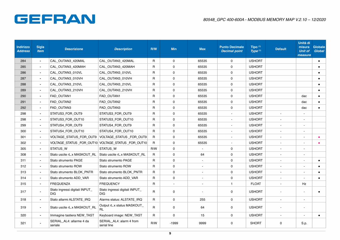
284 - CAL_OUTAN3_420MAL CAL_OUTAN3_420MAL R 0 65535 0 USHORT ●
285 - CAL_OUTAN3_420MAH CAL_OUTAN3_420MAH R 0 65535 0 USHORT ●
286 - CAL_OUTAN3_010VL CAL_OUTAN3_010VL R 0 65535 0 USHORT ●
287 - CAL_OUTAN3_010VH CAL_OUTAN3_010VH R 0 65535 0 USHORT ●
288 - CAL_OUTAN3_210VL CAL_OUTAN3_210VL R 0 65535 0 USHORT ●
289 - CAL_OUTAN3_210VH CAL_OUTAN3_210VH R 0 65535 0 USHORT ●
290 - FAD_OUTAN1 FAD_OUTAN1 R 0 65535 0 USHORT dac ●
291 - FAD_OUTAN2 FAD_OUTAN2 R 0 65535 0 USHORT dac ●
292 - FAD_OUTAN3 FAD_OUTAN3 R 0 65535 0 USHORT dac ●
298 - STATUS3_FOR_OUT9 STATUS3_FOR_OUT9 R 0 65535 - USHORT - -
298 - STATUS3_FOR_OUT10 STATUS3_FOR_OUT10 R 0 65535 - USHORT - -
299 - STATUS4_FOR_OUT9 STATUS4_FOR_OUT9 R 0 65535 - USHORT - -
300 - STATUS4_FOR_OUT10 STATUS4_FOR_OUT10 R 0 65535 - USHORT - -
301 - VOLTAGE_STATUS_FOR_OUT9 VOLTAGE_STATUS _FOR_OUT9 R 0 65535 - USHORT - - ●
302 - VOLTAGE_STATUS _FOR_OUT10 VOLTAGE_STATUS _FOR_OUT10 R 0 65535 - USHORT - - ●
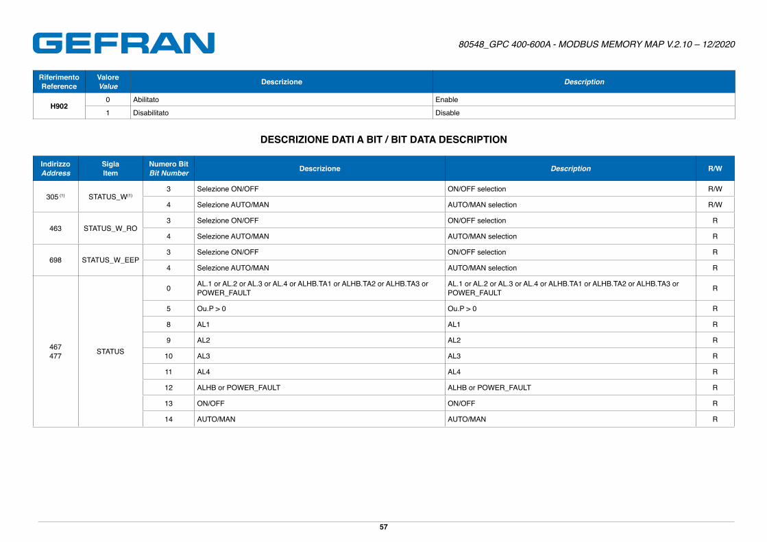
305 - STATUS_W STATUS_W R/W 0 - 0 USHORT - -
308 - Stato uscite rL.x MASKOUT_RL Stato uscite rL.x MASKOUT_RL R 0 64 0 USHORT - -
311 - Stato strumento PAGE Stato strumento PAGE R 0 - 0 USHORT - - ●
312 - Stato strumento ROW Stato strumento ROW R 0 - 0 USHORT - - ●
313 - Stato strumento BLOK_PNTR Stato strumento BLOK_PNTR R 0 - 0 USHORT - - ●
314 - Stato strumento ADD_VAR Stato strumento ADD_VAR R 0 - 0 USHORT - - ●
315 - FREQUENZA FREQUENCY R - - 1 FLOAT - Hz
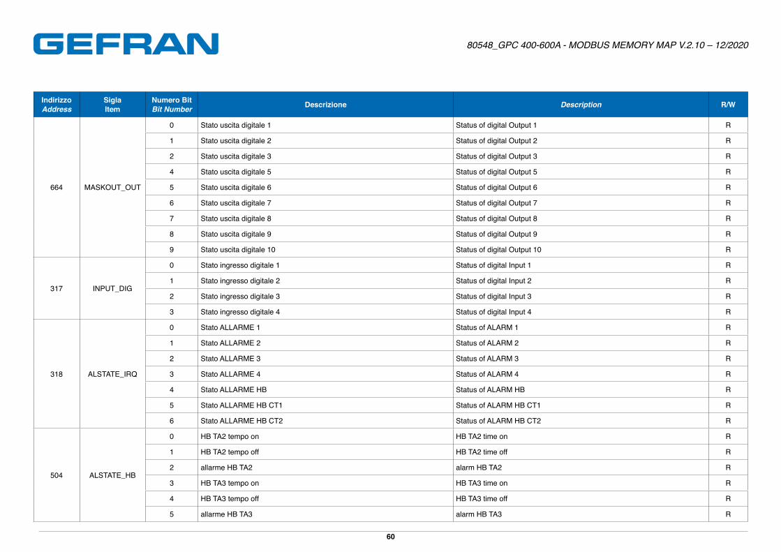
317 - Stato ingressi digitali INPUT_DIG
Stato ingressi digitali INPUT_DIG R 0 - 0 USHORT - - ●
318 - Stato allarmi ALSTATE_IRQ Alarms status: ALSTATE_IRQ R 0 255 0 USHORT - -
319 - Stato uscite rL.x MASKOUT_RL Output rL.x status MASKOUT_RL R 0 64 0 USHORT - -
320 - Immagine tastiera NEW_TAST Keyboard image: NEW_TAST R 0 15 0 USHORT - - ●
321 - SERIAL_AL4: allarme 4 da seriale
SERIAL_AL4: alarm 4 from serial line R/W -1999 9999 0 SHORT 0 S�p�
Page 10
80548_GPC 400-600A - MODBUS MEMORY MAP V.2.10 – 12/2020
10
IndirizzoAddress
SiglaItem Descrizione Description R/W Min Max Punto Decimale
Decimal pointTipo (1)
Type (1) Default
Unità di misuraUnit of
measure
GlobaleGlobal
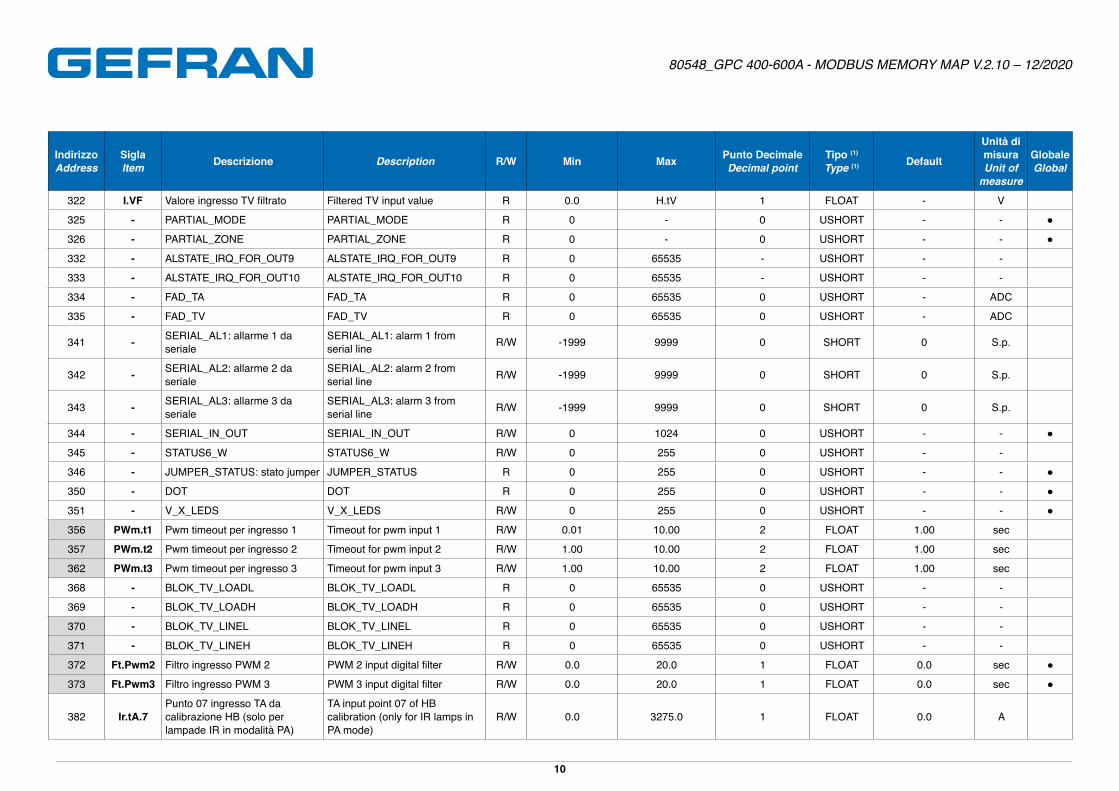
322 I.VF Valore ingresso TV filtrato Filtered TV input value R 0�0 H�tV 1 FLOAT - V
325 - PARTIAL_MODE PARTIAL_MODE R 0 - 0 USHORT - - ●
326 - PARTIAL_ZONE PARTIAL_ZONE R 0 - 0 USHORT - - ●
332 - ALSTATE_IRQ_FOR_OUT9 ALSTATE_IRQ_FOR_OUT9 R 0 65535 - USHORT - -
333 - ALSTATE_IRQ_FOR_OUT10 ALSTATE_IRQ_FOR_OUT10 R 0 65535 - USHORT - -
334 - FAD_TA FAD_TA R 0 65535 0 USHORT - ADC
335 - FAD_TV FAD_TV R 0 65535 0 USHORT - ADC
341 - SERIAL_AL1: allarme 1 da seriale
SERIAL_AL1: alarm 1 from serial line R/W -1999 9999 0 SHORT 0 S�p�
342 - SERIAL_AL2: allarme 2 da seriale
SERIAL_AL2: alarm 2 from serial line R/W -1999 9999 0 SHORT 0 S�p�
343 - SERIAL_AL3: allarme 3 da seriale
SERIAL_AL3: alarm 3 from serial line R/W -1999 9999 0 SHORT 0 S�p�
344 - SERIAL_IN_OUT SERIAL_IN_OUT R/W 0 1024 0 USHORT - - ●
345 - STATUS6_W STATUS6_W R/W 0 255 0 USHORT - -
346 - JUMPER_STATUS: stato jumper JUMPER_STATUS R 0 255 0 USHORT - - ●
350 - DOT DOT R 0 255 0 USHORT - - ●
351 - V_X_LEDS V_X_LEDS R/W 0 255 0 USHORT - - ●
356 PWm.t1 Pwm timeout per ingresso 1 Timeout for pwm input 1 R/W 0�01 10�00 2 FLOAT 1�00 sec
357 PWm.t2 Pwm timeout per ingresso 2 Timeout for pwm input 2 R/W 1�00 10�00 2 FLOAT 1�00 sec
362 PWm.t3 Pwm timeout per ingresso 3 Timeout for pwm input 3 R/W 1�00 10�00 2 FLOAT 1�00 sec
368 - BLOK_TV_LOADL BLOK_TV_LOADL R 0 65535 0 USHORT - -
369 - BLOK_TV_LOADH BLOK_TV_LOADH R 0 65535 0 USHORT - -
370 - BLOK_TV_LINEL BLOK_TV_LINEL R 0 65535 0 USHORT - -
371 - BLOK_TV_LINEH BLOK_TV_LINEH R 0 65535 0 USHORT - -
372 Ft.Pwm2 Filtro ingresso PWM 2 PWM 2 input digital filter R/W 0�0 20�0 1 FLOAT 0�0 sec ●
373 Ft.Pwm3 Filtro ingresso PWM 3 PWM 3 input digital filter R/W 0�0 20�0 1 FLOAT 0�0 sec ●
382 Ir.tA.7Punto 07 ingresso TA da calibrazione HB (solo per lampade IR in modalità PA)
TA input point 07 of HB calibration (only for IR lamps in PA mode)
R/W 0�0 3275�0 1 FLOAT 0�0 A
(800�0/1200�0/1000�0)
Page 11
80548_GPC 400-600A - MODBUS MEMORY MAP V.2.10 – 12/2020
11
IndirizzoAddress
SiglaItem Descrizione Description R/W Min Max Punto Decimale
Decimal pointTipo (1)
Type (1) Default
Unità di misuraUnit of
measure
GlobaleGlobal
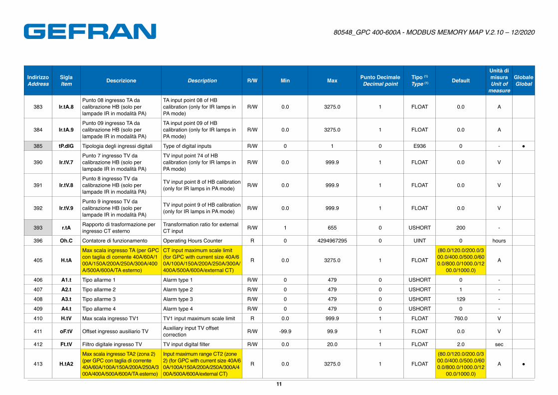
383 Ir.tA.8Punto 08 ingresso TA da calibrazione HB (solo per lampade IR in modalità PA)
TA input point 08 of HB calibration (only for IR lamps in PA mode)
R/W 0�0 3275�0 1 FLOAT 0�0 A
384 Ir.tA.9Punto 09 ingresso TA da calibrazione HB (solo per lampade IR in modalità PA)
TA input point 09 of HB calibration (only for IR lamps in PA mode)
R/W 0�0 3275�0 1 FLOAT 0�0 A
385 tP.dIG Tipologia degli ingressi digitali Type of digital inputs R/W 0 1 0 E936 0 - ●
390 Ir.tV.7Punto 7 ingresso TV da calibrazione HB (solo per lampade IR in modalità PA)
TV input point 74 of HB calibration (only for IR lamps in PA mode)
R/W 0�0 999�9 1 FLOAT 0�0 V
391 Ir.tV.8Punto 8 ingresso TV da calibrazione HB (solo per lampade IR in modalità PA)
TV input point 8 of HB calibration (only for IR lamps in PA mode) R/W 0�0 999�9 1 FLOAT 0�0 V
392 Ir.tV.9Punto 9 ingresso TV da calibrazione HB (solo per lampade IR in modalità PA)
TV input point 9 of HB calibration (only for IR lamps in PA mode) R/W 0�0 999�9 1 FLOAT 0�0 V
393 r.tA Rapporto di trasformazione per ingresso CT esterno
Transformation ratio for external CT input R/W 1 655 0 USHORT 200 -
396 Oh.C Contatore di funzionamento Operating Hours Counter R 0 4294967295 0 UINT 0 hours
405 H.tA
Max scala ingresso TA (per GPC con taglia di corrente 40A/60A/100A/150A/200A/250A/300A/400A/500A/600A/TA esterno)
CT input maximum scale limit (for GPC with current size 40A/60A/100A/150A/200A/250A/300A/400A/500A/600A/external CT)
R 0�0 3275�0 1 FLOAT
(80�0/120�0/200�0/300�0/400�0/500�0/600�0/800�0/1000�0/12
00�0/1000�0)
A
406 A1.t Tipo allarme 1 Alarm type 1 R/W 0 479 0 USHORT 0 -
407 A2.t Tipo allarme 2 Alarm type 2 R/W 0 479 0 USHORT 1 -
408 A3.t Tipo allarme 3 Alarm type 3 R/W 0 479 0 USHORT 129 -
409 A4.t Tipo allarme 4 Alarm type 4 R/W 0 479 0 USHORT 0 -
410 H.tV Max scala ingresso TV1 TV1 input maximum scale limit R 0�0 999�9 1 FLOAT 760�0 V
411 oF.tV Offset ingresso ausiliario TV Auxiliary input TV offset correction R/W -99�9 99�9 1 FLOAT 0�0 V
412 Ft.tV Filtro digitale ingresso TV TV input digital filter R/W 0�0 20�0 1 FLOAT 2�0 sec
413 H.tA2
Max scala ingresso TA2 (zona 2) (per GPC con taglia di corrente40A/60A/100A/150A/200A/250A/300A/400A/500A/600A/TA esterno)
Input maximum range CT2 (zone 2) (for GPC with current size 40A/60A/100A/150A/200A/250A/300A/400A/500A/600A/external CT)
R 0�0 3275�0 1 FLOAT
(80�0/120�0/200�0/300�0/400�0/500�0/600�0/800�0/1000�0/12
00�0/1000�0)
A ●
Page 12
80548_GPC 400-600A - MODBUS MEMORY MAP V.2.10 – 12/2020
12
IndirizzoAddress
SiglaItem Descrizione Description R/W Min Max Punto Decimale
Decimal pointTipo (1)
Type (1) Default
Unità di misuraUnit of
measure
GlobaleGlobal
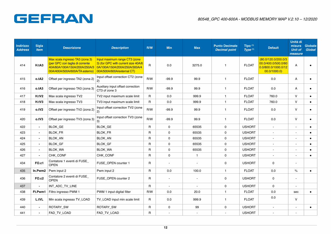
414 H.tA3
Max scala ingresso TA3 (zona 3) (per GPC con taglia di corrente40A/60A/100A/150A/200A/250A/300A/400A/500A/600A/TA esterno)
Input maximum range CT3 (zone 3) (for GPC with current size 40A/60A/100A/150A/200A/250A/300A/400A/500A/600A/external CT)
R 0�0 3275�0 1 FLOAT
(80�0/120�0/200�0/300�0/400�0/500�0/600�0/800�0/1000�0/12
00�0/1000�0)
A ●
415 o.tA2 Offset per ingresso TA2 (zona 2) Input offset correction CT2 (zone 2) R/W -99�9 99�9 1 FLOAT 0�0 A ●
416 o.tA3 Offset per ingresso TA3 (zona 3) Auxiliary input offset correction CT3 of zone 3 R/W -99�9 99�9 1 FLOAT 0�0 A ●
417 H.tV2 Max scala ingresso TV2 TV2 input maximum scale limit R 0�0 999�9 1 FLOAT 760�0 V ●
418 H.tV3 Max scala ingresso TV3 TV3 input maximum scale limit R 0�0 999�9 1 FLOAT 760�0 V ●
419 o.tV2 Offset per ingresso TV2 (zona 2) Input offset correction TV2 (zone 2) R/W -99�9 99�9 1 FLOAT 0�0 V ●
420 o.tV3 Offset per ingresso TV3 (zona 3) Input offset correction TV3 (zone 3) R/W -99�9 99�9 1 FLOAT 0�0 V ●
422 - BLOK_GE BLOK_GE R 0 65535 0 USHORT - - ●
423 - BLOK_FR BLOK_FR R 0 65535 0 USHORT - - ●
424 - BLOK_AN BLOK_AN R 0 65535 0 USHORT - - ●
425 - BLOK_GF BLOK_GF R 0 65535 0 USHORT - - ●
426 - BLOK_WA BLOK_WA R 0 65535 0 USHORT - - ●
427 - CHK_CONF CHK_CONF R 0 1 0 USHORT - - ●
434 FO.c1 Contatore 1 eventi di FUSE_OPEN FUSE_OPEN counter 1 R - - 0 USHORT 0 -
435 In.Pwm2 Pwm input 2 Pwm input 2 R 0�0 100�0 1 FLOAT 0�0 % ●
436 FO.c2 Contatore 2 eventi di FUSE_OPEN FUSE_OPEN counter 2 R - - 0 USHORT 0 -
437 - INT_ADC_TV_LINE R - - 0 USHORT 0 -
438 Ft.Pwm1 Filtro ingresso PWM 1 PWM 1 input digital filter R/W 0�0 20�0 1 FLOAT 0�0 sec ●
439 L.tVL Min scala ingresso TV_LOAD TV_LOAD input min scale limit R 0�0 999�9 1 FLOAT 0�0 V
440 - ROTARY_SW ROTARY_SW R 0 99 0 USHORT - - ●
441 - FAD_TV_LOAD FAD_TV_LOAD R - - - USHORT - -
Page 13
80548_GPC 400-600A - MODBUS MEMORY MAP V.2.10 – 12/2020
13
IndirizzoAddress
SiglaItem Descrizione Description R/W Min Max Punto Decimale
Decimal pointTipo (1)
Type (1) Default
Unità di misuraUnit of
measure
GlobaleGlobal
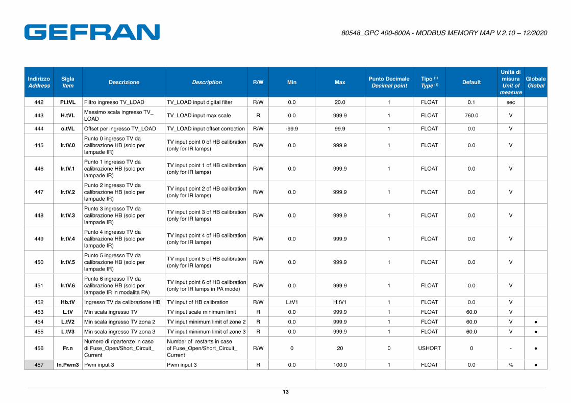
442 Ft.tVL Filtro ingresso TV_LOAD TV_LOAD input digital filter R/W 0�0 20�0 1 FLOAT 0�1 sec
443 H.tVL Massimo scala ingresso TV_LOAD TV_LOAD input max scale R 0�0 999�9 1 FLOAT 760�0 V
444 o.tVL Offset per ingresso TV_LOAD TV_LOAD input offset correction R/W -99�9 99�9 1 FLOAT 0�0 V
445 Ir.tV.0Punto 0 ingresso TV da calibrazione HB (solo per lampade IR)
TV input point 0 of HB calibration (only for IR lamps) R/W 0�0 999�9 1 FLOAT 0�0 V
446 Ir.tV.1Punto 1 ingresso TV da calibrazione HB (solo per lampade IR)
TV input point 1 of HB calibration (only for IR lamps) R/W 0�0 999�9 1 FLOAT 0�0 V
447 Ir.tV.2Punto 2 ingresso TV da calibrazione HB (solo per lampade IR)
TV input point 2 of HB calibration (only for IR lamps) R/W 0�0 999�9 1 FLOAT 0�0 V
448 Ir.tV.3Punto 3 ingresso TV da calibrazione HB (solo per lampade IR)
TV input point 3 of HB calibration (only for IR lamps) R/W 0�0 999�9 1 FLOAT 0�0 V
449 Ir.tV.4Punto 4 ingresso TV da calibrazione HB (solo per lampade IR)
TV input point 4 of HB calibration (only for IR lamps) R/W 0�0 999�9 1 FLOAT 0�0 V
450 Ir.tV.5Punto 5 ingresso TV da calibrazione HB (solo per lampade IR)
TV input point 5 of HB calibration (only for IR lamps) R/W 0�0 999�9 1 FLOAT 0�0 V
451 Ir.tV.6Punto 6 ingresso TV da calibrazione HB (solo per lampade IR in modalità PA)
TV input point 6 of HB calibration (only for IR lamps in PA mode) R/W 0�0 999�9 1 FLOAT 0�0 V
452 Hb.tV Ingresso TV da calibrazione HB TV input of HB calibration R/W L�tV1 H�tV1 1 FLOAT 0�0 V
453 L.tV Min scala ingresso TV TV input scale minimum limit R 0�0 999�9 1 FLOAT 60�0 V
454 L.tV2 Min scala ingresso TV zona 2 TV input minimum limit of zone 2 R 0�0 999�9 1 FLOAT 60�0 V ●
455 L.tV3 Min scala ingresso TV zona 3 TV input minimum limit of zone 3 R 0�0 999�9 1 FLOAT 60�0 V ●
456 Fr.nNumero di ripartenze in caso di Fuse_Open/Short_Circuit_Current
Number of restarts in case of Fuse_Open/Short_Circuit_Current
R/W 0 20 0 USHORT 0 - ●
457 In.Pwm3 Pwm input 3 Pwm input 3 R 0�0 100�0 1 FLOAT 0�0 % ●
Page 14
80548_GPC 400-600A - MODBUS MEMORY MAP V.2.10 – 12/2020
14
IndirizzoAddress
SiglaItem Descrizione Description R/W Min Max Punto Decimale
Decimal pointTipo (1)
Type (1) Default
Unità di misuraUnit of
measure
GlobaleGlobal
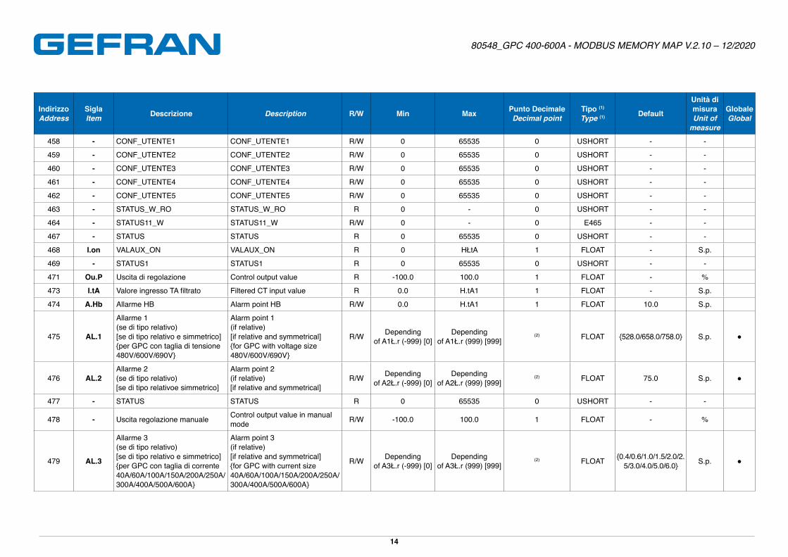
458 - CONF_UTENTE1 CONF_UTENTE1 R/W 0 65535 0 USHORT - -
459 - CONF_UTENTE2 CONF_UTENTE2 R/W 0 65535 0 USHORT - -
460 - CONF_UTENTE3 CONF_UTENTE3 R/W 0 65535 0 USHORT - -
461 - CONF_UTENTE4 CONF_UTENTE4 R/W 0 65535 0 USHORT - -
462 - CONF_UTENTE5 CONF_UTENTE5 R/W 0 65535 0 USHORT - -
463 - STATUS_W_RO STATUS_W_RO R 0 - 0 USHORT - -
464 - STATUS11_W STATUS11_W R/W 0 - 0 E465 - -
467 - STATUS STATUS R 0 65535 0 USHORT - -
468 I.on VALAUX_ON VALAUX_ON R 0 HŁtA 1 FLOAT - S�p�
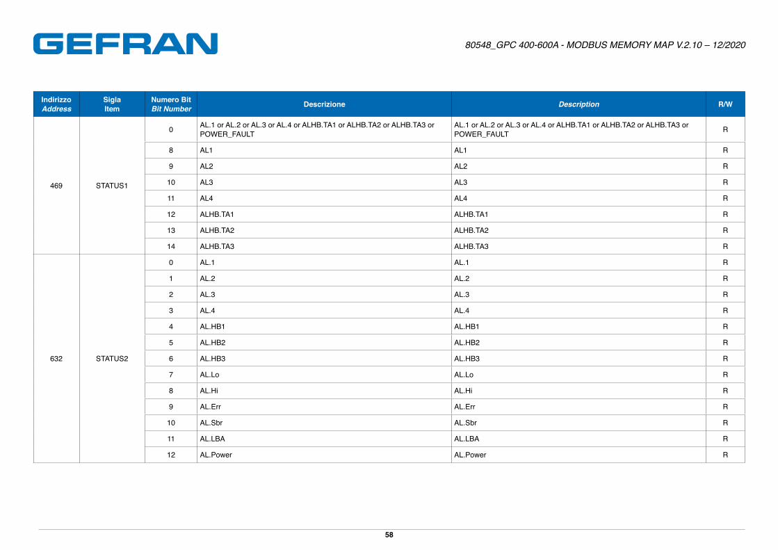
469 - STATUS1 STATUS1 R 0 65535 0 USHORT - -
471 Ou.P Uscita di regolazione Control output value R -100�0 100�0 1 FLOAT - %
473 I.tA Valore ingresso TA filtrato Filtered CT input value R 0�0 H�tA1 1 FLOAT - S�p�
474 A.Hb Allarme HB Alarm point HB R/W 0�0 H�tA1 1 FLOAT 10�0 S�p�
475 AL.1
Allarme 1(se di tipo relativo)[se di tipo relativo e simmetrico]{per GPC con taglia di tensione 480V/600V/690V}
Alarm point 1(if relative)[if relative and symmetrical]{for GPC with voltage size 480V/600V/690V}
R/W Dependingof A1Ł.r (-999) [0]
Dependingof A1Ł.r (999) [999]
(2) FLOAT {528�0/658�0/758�0} S�p� ●
476 AL.2Allarme 2(se di tipo relativo)[se di tipo relativoe simmetrico]
Alarm point 2(if relative)[if relative and symmetrical]
R/W Dependingof A2Ł.r (-999) [0]
Dependingof A2Ł.r (999) [999]
(2) FLOAT 75�0 S�p� ●
477 - STATUS STATUS R 0 65535 0 USHORT - -
478 - Uscita regolazione manuale Control output value in manual mode R/W -100�0 100�0 1 FLOAT - %
479 AL.3
Allarme 3(se di tipo relativo)[se di tipo relativo e simmetrico]{per GPC con taglia di corrente 40A/60A/100A/150A/200A/250A/300A/400A/500A/600A}
Alarm point 3(if relative)[if relative and symmetrical]{for GPC with current size40A/60A/100A/150A/200A/250A/300A/400A/500A/600A}
R/W Dependingof A3Ł.r (-999) [0]
Dependingof A3Ł.r (999) [999]
(2) FLOAT {0�4/0�6/1�0/1�5/2�0/2�5/3�0/4�0/5�0/6�0} S�p� ●
Page 15
80548_GPC 400-600A - MODBUS MEMORY MAP V.2.10 – 12/2020
15
IndirizzoAddress
SiglaItem Descrizione Description R/W Min Max Punto Decimale
Decimal pointTipo (1)
Type (1) Default
Unità di misuraUnit of
measure
GlobaleGlobal
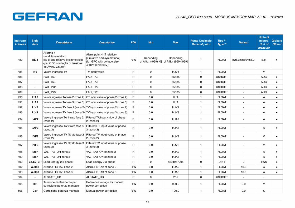
480 AL.4
Allarme 4 (se di tipo relativo)[se di tipo relativo e simmetrico]{per GPC con taglia di tensione 480V/600V/690V}
Alarm point 4 (if relative)[if relative and symmetrical]{for GPC with voltage size 480V/600V/690V}
R/W Dependingof A4Ł.r (-999) [0]
Dependingof A4Ł.r (999) [999]
(2) FLOAT {528�0/658�0/758�0} S�p� ●
485 I.tV Valore ingresso TV TV input value R 0 H�tV1 1 FLOAT - V
486 - FAD_TA2 FAD_TA2 R 0 65535 0 USHORT - ADC ●
487 - FAD_TA3 FAD_TA3 R 0 65535 0 USHORT - ADC ●
488 - FAD_TV2 FAD_TV2 R 0 65535 0 USHORT - ADC ●
489 - FAD_TV3 FAD_TV3 R 0 65535 0 USHORT - ADC ●
490 I.tA2 Valore ingresso TA fase 2 (zona 2) CT input value of phase 2 (zone 2) R 0�0 H�tA 1 FLOAT - A ●
491 I.tA3 Valore ingresso TA fase 3 (zona 3) CT input value of phase 3 (zone 3) R 0�0 H�tA 1 FLOAT - A ●
492 I.tV2 Valore ingresso TV fase 2 (zona 2) TV input value of phase 2 (zone 2) R 0�0 H�tV2 1 FLOAT - A ●
493 I.tV3 Valore ingresso TV fase 3 (zona 3) TV input value of phase 3 (zone 3) R 0�0 H�tV3 1 FLOAT - A ●
494 I.AF2 Valore ingresso TA filtrato fase 2 (zona 2)
Filtered TA input value of phase 2 (zone 2) R 0�0 H�tA2 1 FLOAT - A ●
495 I.AF3 Valore ingresso TA filtrato fase 3 (zona 3)
Filtered CT input value of phase 3 (zone 3) R 0�0 H�tA3 1 FLOAT - A ●
496 I.VF2 Valore ingresso TV filtrato fase 2 (zona 2)
Filtered TV input value of phase 2 (zone 2) R 0�0 H�tV2 1 FLOAT - V ●
497 I.VF3 Valore ingresso TV filtrato fase 3 (zona 3)
Filtered TV input value of phase 3 (zone 3) R 0�0 H�tV3 1 FLOAT - V ●
498 I.2on VAL_TA2_ON zona 2 VAL_TA2_ON of zone 2 R 0�0 H�tA2 1 FLOAT - A ●
499 I.3on VAL_TA3_ON zona 3 VAL_TA3_ON of zone 3 R 0�0 H�tA3 1 FLOAT - A ●
500 Ld.E2_3P Load Energy 2 3-phase Load Energy 2 3-phase R 0 4294967295 0 UINT 0 kWh ●
502 A.Hb2 Allarme HB TA2 zona 2 Alarm HB TA2 of zone 2 R/W 0�0 H�tA2 1 FLOAT 10�0 A ●
503 A.Hb3 Allarme HB TA3 zona 3 Alarm HB TA3 of zone 3 R/W 0�0 H�tA3 1 FLOAT 10�0 A ●
504 - ALSTATE_HB ALSTATE_HB R 0 255 0 USHORT - -
505 RIF Tensione di riferimento per correzione potenza manuale
Reference voltage for manual power correction R/W 0�0 999�9 1 FLOAT 0�0 V
506 Cor Correzione potenza manuale Manual power correction R/W 0�0 100�0 1 FLOAT 0�0 %
Page 16
80548_GPC 400-600A - MODBUS MEMORY MAP V.2.10 – 12/2020
16
IndirizzoAddress
SiglaItem Descrizione Description R/W Min Max Punto Decimale
Decimal pointTipo (1)
Type (1) Default
Unità di misuraUnit of
measure
GlobaleGlobal
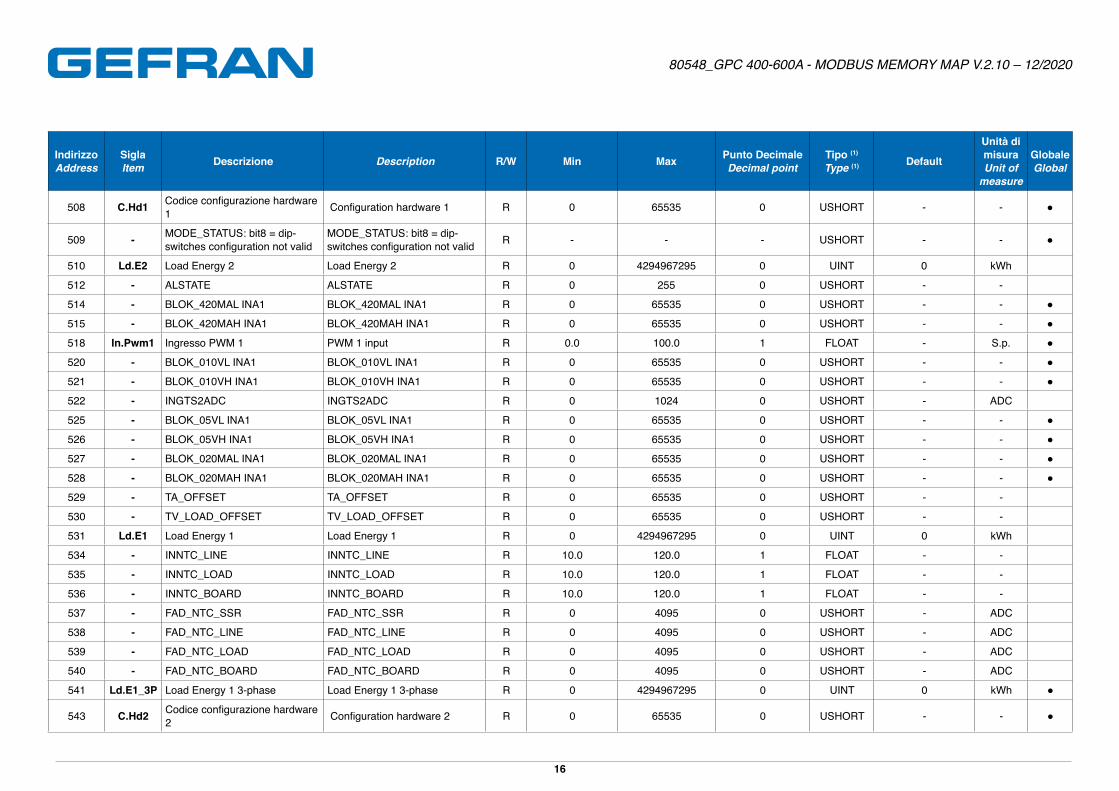
508 C.Hd1 Codice configurazione hardware 1 Configuration hardware 1 R 0 65535 0 USHORT - - ●
509 - MODE_STATUS: bit8 = dip-switches configuration not valid
MODE_STATUS: bit8 = dip-switches configuration not valid R - - - USHORT - - ●
510 Ld.E2 Load Energy 2 Load Energy 2 R 0 4294967295 0 UINT 0 kWh
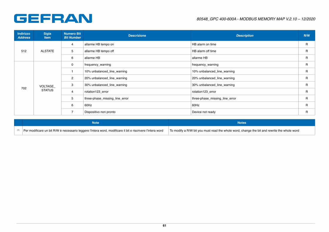
512 - ALSTATE ALSTATE R 0 255 0 USHORT - -
514 - BLOK_420MAL INA1 BLOK_420MAL INA1 R 0 65535 0 USHORT - - ●
515 - BLOK_420MAH INA1 BLOK_420MAH INA1 R 0 65535 0 USHORT - - ●
518 In.Pwm1 Ingresso PWM 1 PWM 1 input R 0�0 100�0 1 FLOAT - S�p� ●
520 - BLOK_010VL INA1 BLOK_010VL INA1 R 0 65535 0 USHORT - - ●
521 - BLOK_010VH INA1 BLOK_010VH INA1 R 0 65535 0 USHORT - - ●
522 - INGTS2ADC INGTS2ADC R 0 1024 0 USHORT - ADC
525 - BLOK_05VL INA1 BLOK_05VL INA1 R 0 65535 0 USHORT - - ●
526 - BLOK_05VH INA1 BLOK_05VH INA1 R 0 65535 0 USHORT - - ●
527 - BLOK_020MAL INA1 BLOK_020MAL INA1 R 0 65535 0 USHORT - - ●
528 - BLOK_020MAH INA1 BLOK_020MAH INA1 R 0 65535 0 USHORT - - ●
529 - TA_OFFSET TA_OFFSET R 0 65535 0 USHORT - -
530 - TV_LOAD_OFFSET TV_LOAD_OFFSET R 0 65535 0 USHORT - -
531 Ld.E1 Load Energy 1 Load Energy 1 R 0 4294967295 0 UINT 0 kWh
534 - INNTC_LINE INNTC_LINE R 10�0 120�0 1 FLOAT - -
535 - INNTC_LOAD INNTC_LOAD R 10�0 120�0 1 FLOAT - -
536 - INNTC_BOARD INNTC_BOARD R 10�0 120�0 1 FLOAT - -
537 - FAD_NTC_SSR FAD_NTC_SSR R 0 4095 0 USHORT - ADC
538 - FAD_NTC_LINE FAD_NTC_LINE R 0 4095 0 USHORT - ADC
539 - FAD_NTC_LOAD FAD_NTC_LOAD R 0 4095 0 USHORT - ADC
540 - FAD_NTC_BOARD FAD_NTC_BOARD R 0 4095 0 USHORT - ADC
541 Ld.E1_3P Load Energy 1 3-phase Load Energy 1 3-phase R 0 4294967295 0 UINT 0 kWh ●
543 C.Hd2 Codice configurazione hardware 2 Configuration hardware 2 R 0 65535 0 USHORT - - ●
Page 17
80548_GPC 400-600A - MODBUS MEMORY MAP V.2.10 – 12/2020
17
IndirizzoAddress
SiglaItem Descrizione Description R/W Min Max Punto Decimale
Decimal pointTipo (1)
Type (1) Default
Unità di misuraUnit of
measure
GlobaleGlobal
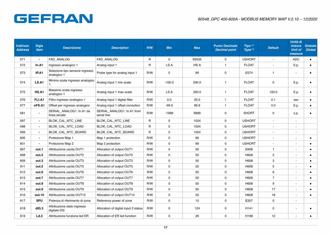
571 - FAD_ANALOG FAD_ANALOG R 0 65535 0 USHORT - ADC ●
572 In.A1 Ingresso analogico 1 Analog input 1 R LS�A HS�A 1 FLOAT - S�p� ●
573 tP.A1 Selezione tipo sensore ingresso analogico 1 Probe type for analog input 1 R/W 0 99 0 E574 1 - ●
574 LS.A1 Minimo scala ingresso analogico 1 Analog input 1 min scale R/W -100�0 200�0 1 FLOAT 0 S�p� ●
575 HS.A1 Massimo scala ingresso analogico 1 Analog input 1 max scale R/W LS�A 200�0 1 FLOAT 100�0 S�p� ●
576 FLt.A1 Filtro ingresso analogico 1 Analog input 1 digital filter R/W 0�0 20�0 1 FLOAT 0�1 sec ●
577 oFS.A1 Offset per ingresso analogico Analog input 1 offset correction R/W -99�9 99�9 1 FLOAT 0�0 S�p� ●
581 - SERIAL_ANALOG1: In.A1 da linea seriale
SERIAL_ANALOG1: In.A1 from serial line R/W -1999 9999 0 SHORT 0 s�p� ●
597 - BLOK_CAL_NTC_LINE BLOK_CAL_NTC_LINE R 0 1024 0 USHORT - -
598 - BLOK_CAL_NTC_LOAD BLOK_CAL_NTC_LOAD R 0 1024 0 USHORT - -
599 - BLOK_CAL_NTC_BOARD BLOK_CAL_NTC_BOARD R 0 1024 0 USHORT - -
600 - Protezione Map 1 Map 1 protection R/W 0 99 0 USHORT - - ●
601 - Protezione Map 2 Map 2 protection R/W 0 99 0 USHORT - - ●
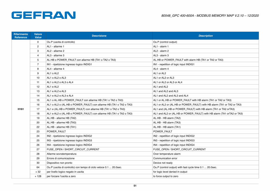
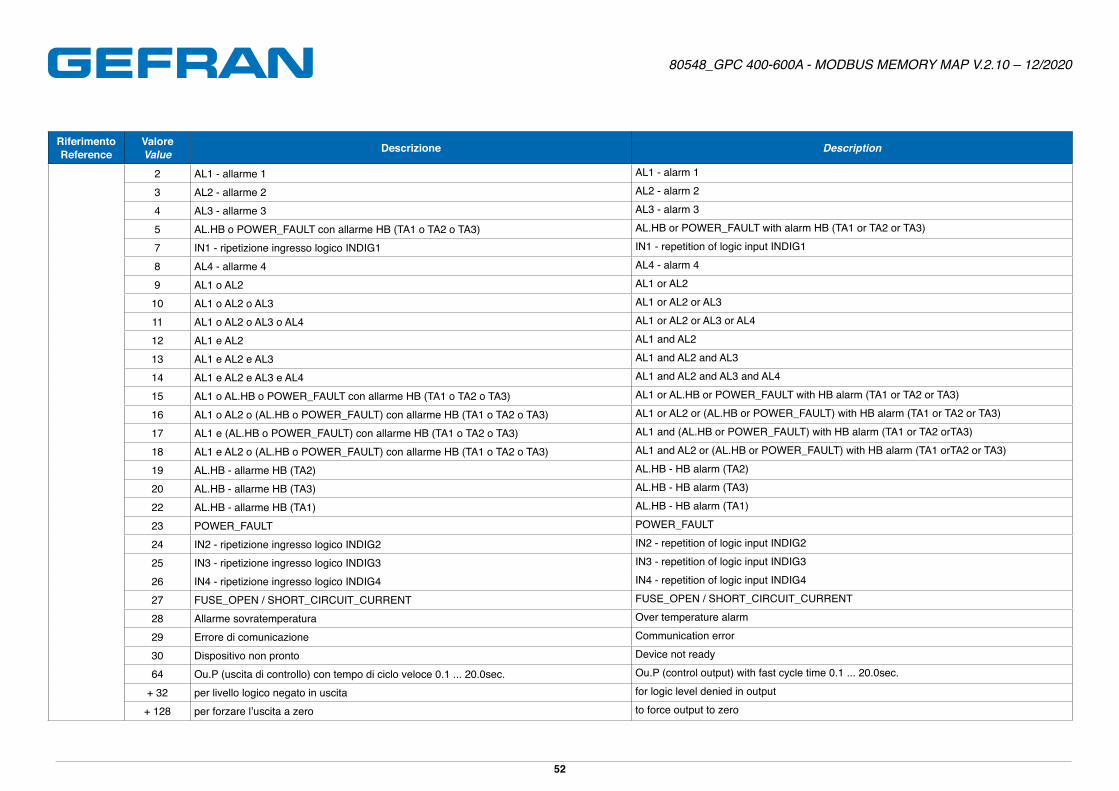
607 out.1 Attribuzione uscita OUT1 Allocation of output OUT1 R/W 0 50 0 E608 1 - ●
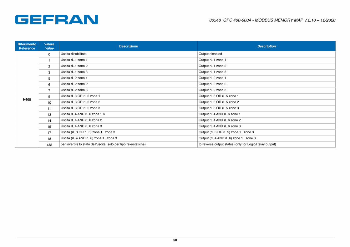
608 out.2 Attribuzione uscita OUT2 Allocation of output OUT2 R/W 0 50 0 H608 2 - ●
609 out.3 Attribuzione uscita OUT3 Allocation of output OUT3 R/W 0 50 0 H608 3 - ●
611 out.5 Attribuzione uscita OUT5 Allocation of output OUT5 R/W 0 50 0 H608 5 - ●
612 out.6 Attribuzione uscita OUT6 Allocation of output OUT6 R/W 0 50 0 H608 6 - ●
613 out.7 Attribuzione uscita OUT7 Allocation of output OUT7 R/W 0 50 0 H608 7 - ●
614 out.8 Attribuzione uscita OUT8 Allocation of output OUT8 R/W 0 50 0 H608 9 - ●
615 out.9 Attribuzione uscita OUT9 Allocation of output OUT9 R/W 0 50 0 H608 17 - ●
616 out.10 Attribuzione uscita OUT10 Allocation of output OUT10 R/W 0 50 0 H608 18 - ●
617 SPU Potenza di riferimento di zona Reference power of zone R/W 0 15 0 E207 0 -
618 dIG.2 Attribuzione stato ingresso digitale DI2 Allocation of digital input 2 status R/W 0 124 0 H141 0 - ●
619 Ld.2 Attribuzione funzione led ER Allocation of ER led function R/W 0 29 0 H198 12 - ●
Page 18
80548_GPC 400-600A - MODBUS MEMORY MAP V.2.10 – 12/2020
18
IndirizzoAddress
SiglaItem Descrizione Description R/W Min Max Punto Decimale
Decimal pointTipo (1)
Type (1) Default
Unità di misuraUnit of
measure
GlobaleGlobal
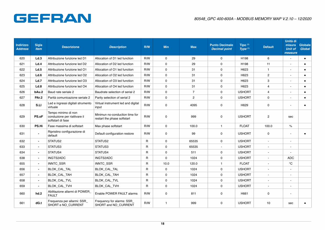
620 Ld.3 Attribuzione funzione led D1 Allocation of D1 led function R/W 0 29 0 H198 6 - ●
621 Ld.4 Attribuzione funzione led D2 Allocation of D2 led function R/W 0 29 0 H198 11 - ●
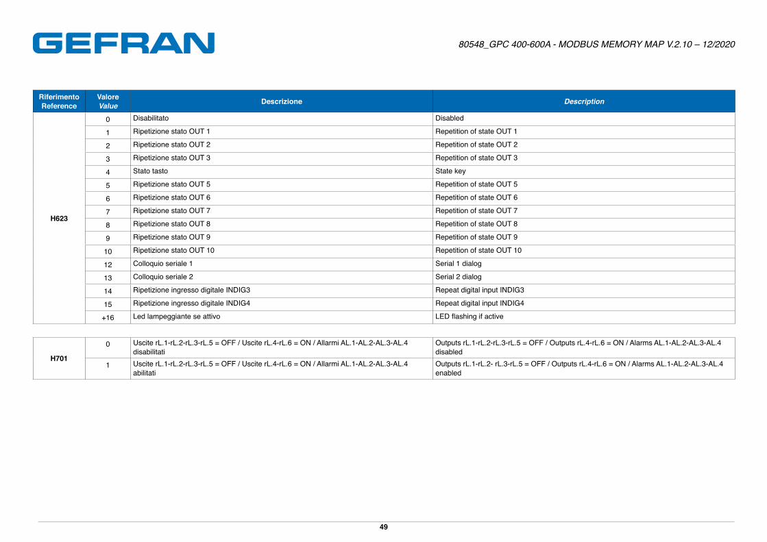
622 Ld.5 Attribuzione funzione led O1 Allocation of O1 led function R/W 0 31 0 H623 1 - ●
623 Ld.6 Attribuzione funzione led O2 Allocation of O2 led function R/W 0 31 0 H623 2 - ●
624 Ld.7 Attribuzione funzione led O3 Allocation of O3 led function R/W 0 31 0 H623 3 - ●
625 Ld.8 Attribuzione funzione led O4 Allocation of O4 led function R/W 0 31 0 H623 4 - ●
626 bAu.2 Baud rate seriale 2 Baudrate selection of serial 2 R/W 0 7 0 USHORT 4 - ●
627 PAr.2 Parità comunicazione seriale 2 Parity selection of serial 2 R/W 0 2 0 USHORT 0 - ●
628 S.LI Led e ingressi digitali strumento virtuale
Virtual instrument led and digital input R/W 0 4095 0 H629 0 - ●
629 PS.oFTempo minimo di non conduzione per riattivare il softstart di fase
Minimun no-conduction time for restart the phase softstart R/W 0 999 0 USHORT 2 sec
630 PS.Hi Fase massima di softstart Max phase softstart R/W 0 100�0 1 FLOAT 100�0 %
631 - Ripristino configurazione di default Default configuration restore R/W 0 99 0 USHORT 0 - ●
632 - STATUS2 STATUS2 R 0 65535 0 USHORT - -
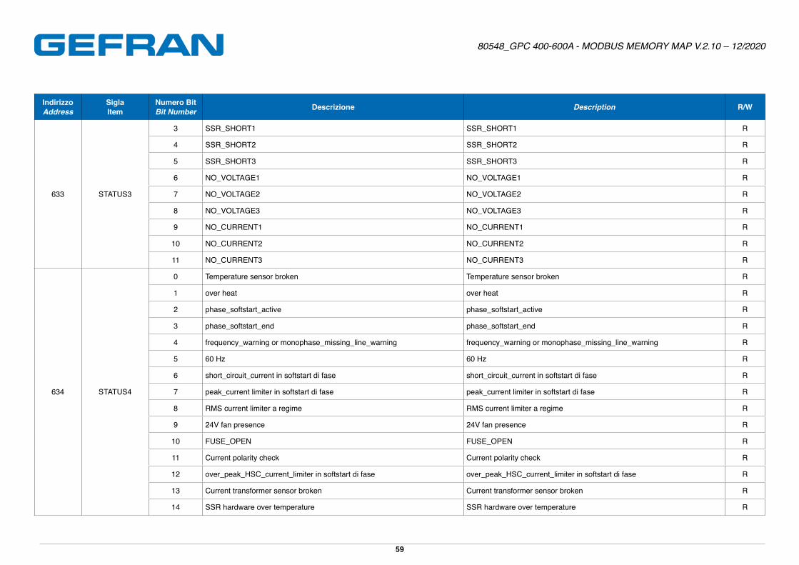
633 - STATUS3 STATUS3 R 0 65535 - USHORT - -
634 - STATUS4 STATUS4 R 0 511 0 USHORT - -
638 - INGTS2ADC INGTS2ADC R 0 1024 0 USHORT - ADC
655 - INNTC_SSR INNTC_SSR R 10�0 120�0 1 FLOAT - °C
656 - BLOK_CAL_TAL BLOK_CAL_TAL R 0 1024 0 USHORT - -
657 - BLOK_CAL_TAH BLOK_CAL_TAH R 0 1024 0 USHORT - -
658 - BLOK_CAL_TVL BLOK_CAL_TVL R 0 1024 0 USHORT - -
659 - BLOK_CAL_TVH BLOK_CAL_TVH R 0 1024 0 USHORT - -
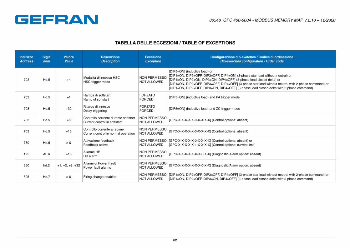
660 hd.2 Abilitazione allarmi di POWER_FAULT Enable POWER FAULT alarms R/W 0 811 0 H661 0 -
661 dG.t Frequenza per allarmi: SSR_SHORT e NO_CURRENT
Frequency for alarms: SSR_SHORT and NO_CURRENT R/W 1 999 0 USHORT 10 sec ●
Page 19
80548_GPC 400-600A - MODBUS MEMORY MAP V.2.10 – 12/2020
19
IndirizzoAddress
SiglaItem Descrizione Description R/W Min Max Punto Decimale
Decimal pointTipo (1)
Type (1) Default
Unità di misuraUnit of
measure
GlobaleGlobal
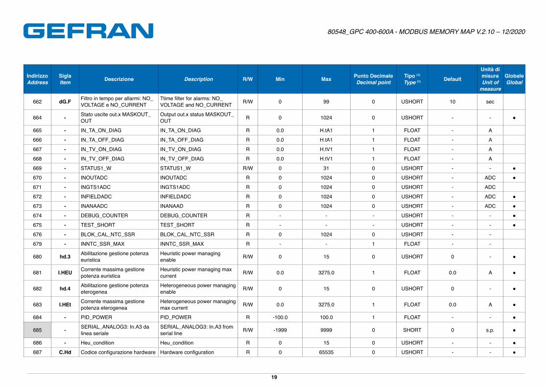
662 dG.F Filtro in tempo per allarmi: NO_VOLTAGE e NO_CURRENT
Ttime filter for alarms: NO_VOLTAGE and NO_CURRENT R/W 0 99 0 USHORT 10 sec
664 - Stato uscite out.x MASKOUT_OUT
Output out.x status MASKOUT_OUT R 0 1024 0 USHORT - - ●
665 - IN_TA_ON_DIAG IN_TA_ON_DIAG R 0�0 H�tA1 1 FLOAT - A
666 - IN_TA_OFF_DIAG IN_TA_OFF_DIAG R 0�0 H�tA1 1 FLOAT - A
667 - IN_TV_ON_DIAG IN_TV_ON_DIAG R 0�0 H�tV1 1 FLOAT - A
668 - IN_TV_OFF_DIAG IN_TV_OFF_DIAG R 0�0 H�tV1 1 FLOAT - A
669 - STATUS1_W STATUS1_W R/W 0 31 0 USHORT - - ●
670 - INOUTADC INOUTADC R 0 1024 0 USHORT - ADC ●
671 - INGTS1ADC INGTS1ADC R 0 1024 0 USHORT - ADC
672 - INFIELDADC INFIELDADC R 0 1024 0 USHORT - ADC ●
673 - INANAADC INANAAD R 0 1024 0 USHORT - ADC ●
674 - DEBUG_COUNTER DEBUG_COUNTER R - - - USHORT - - ●
675 - TEST_SHORT TEST_SHORT R - - - USHORT - - ●
676 - BLOK_CAL_NTC_SSR BLOK_CAL_NTC_SSR R 0 1024 0 USHORT - -
679 - INNTC_SSR_MAX INNTC_SSR_MAX R - - 1 FLOAT - -
680 hd.3 Abilitazione gestione potenza euristica
Heuristic power managing enable R/W 0 15 0 USHORT 0 - ●
681 I.HEU Corrente massima gestione potenza euristica
Heuristic power managing max current R/W 0�0 3275�0 1 FLOAT 0�0 A ●
682 hd.4 Abilitazione gestione potenza eterogenea
Heterogeneous power managing enable R/W 0 15 0 USHORT 0 - ●
683 I.HEt Corrente massima gestione potenza eterogenea
Heterogeneous power managing max current R/W 0�0 3275�0 1 FLOAT 0�0 A ●
684 - PID_POWER PID_POWER R -100�0 100�0 1 FLOAT - - ●
685 - SERIAL_ANALOG3: In.A3 da linea seriale
SERIAL_ANALOG3: In.A3 from serial line R/W -1999 9999 0 SHORT 0 s�p� ●
686 - Heu_condition Heu_condition R 0 15 0 USHORT - - ●
687 C.Hd Codice configurazione hardware Hardware configuration R 0 65535 0 USHORT - - ●
Page 20
80548_GPC 400-600A - MODBUS MEMORY MAP V.2.10 – 12/2020
20
IndirizzoAddress
SiglaItem Descrizione Description R/W Min Max Punto Decimale
Decimal pointTipo (1)
Type (1) Default
Unità di misuraUnit of
measure
GlobaleGlobal
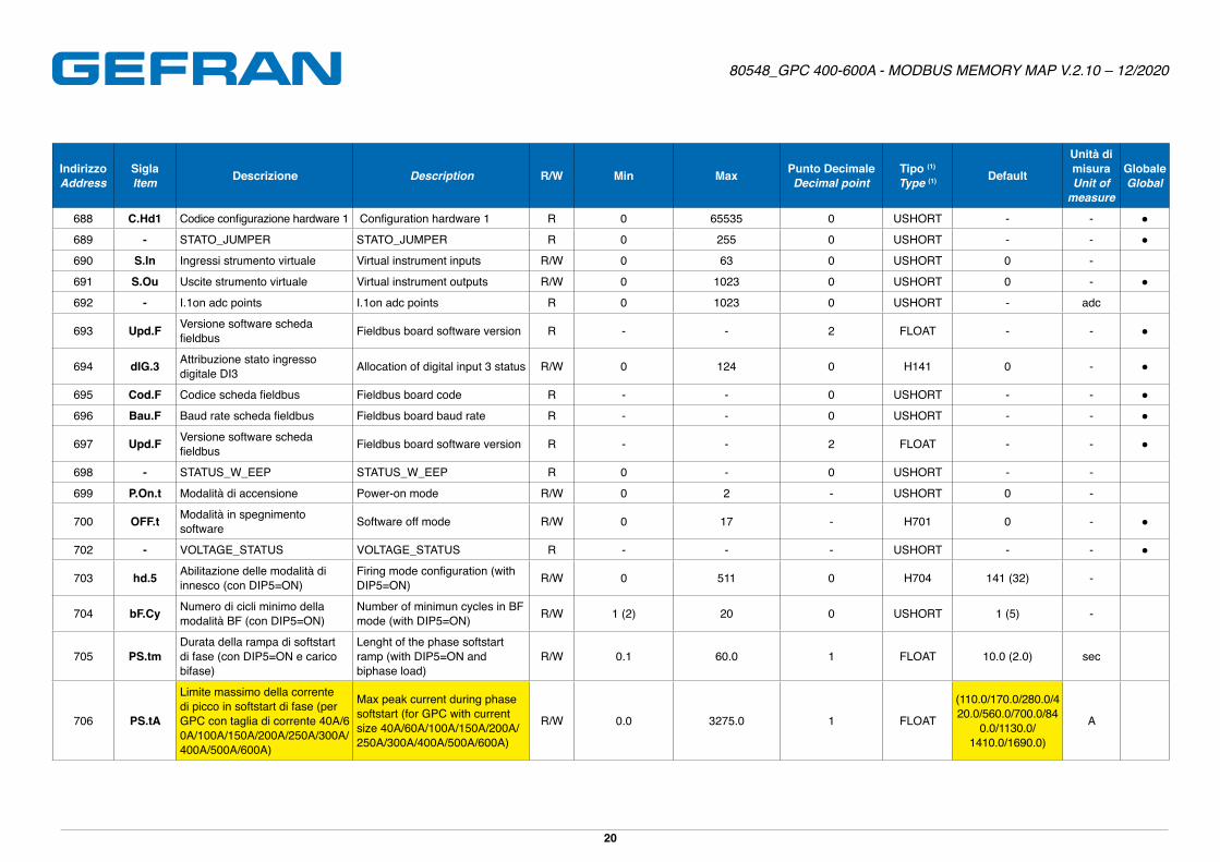
688 C.Hd1 Codice configurazione hardware 1 Configuration hardware 1 R 0 65535 0 USHORT - - ●
689 - STATO_JUMPER STATO_JUMPER R 0 255 0 USHORT - - ●
690 S.In Ingressi strumento virtuale Virtual instrument inputs R/W 0 63 0 USHORT 0 -
691 S.Ou Uscite strumento virtuale Virtual instrument outputs R/W 0 1023 0 USHORT 0 - ●
692 - I�1on adc points I�1on adc points R 0 1023 0 USHORT - adc
693 Upd.F Versione software scheda fieldbus Fieldbus board software version R - - 2 FLOAT - - ●
694 dIG.3 Attribuzione stato ingresso digitale DI3 Allocation of digital input 3 status R/W 0 124 0 H141 0 - ●
695 Cod.F Codice scheda fieldbus Fieldbus board code R - - 0 USHORT - - ●
696 Bau.F Baud rate scheda fieldbus Fieldbus board baud rate R - - 0 USHORT - - ●
697 Upd.F Versione software scheda fieldbus Fieldbus board software version R - - 2 FLOAT - - ●
698 - STATUS_W_EEP STATUS_W_EEP R 0 - 0 USHORT - -
699 P.On.t Modalità di accensione Power-on mode R/W 0 2 - USHORT 0 -
700 OFF.t Modalità in spegnimento software Software off mode R/W 0 17 - H701 0 - ●
702 - VOLTAGE_STATUS VOLTAGE_STATUS R - - - USHORT - - ●
703 hd.5 Abilitazione delle modalità di innesco (con DIP5=ON)
Firing mode configuration (with DIP5=ON) R/W 0 511 0 H704 141 (32) -
704 bF.Cy Numero di cicli minimo della modalità BF (con DIP5=ON)
Number of minimun cycles in BF mode (with DIP5=ON) R/W 1 (2) 20 0 USHORT 1 (5) -
705 PS.tmDurata della rampa di softstartdi fase (con DIP5=ON e carico bifase)
Lenght of the phase softstartramp (with DIP5=ON and biphase load)
R/W 0�1 60�0 1 FLOAT 10�0 (2�0) sec
706 PS.tA
Limite massimo della corrente di picco in softstart di fase (per GPC con taglia di corrente 40A/60A/100A/150A/200A/250A/300A/400A/500A/600A)
Max peak current during phase softstart (for GPC with current size 40A/60A/100A/150A/200A/250A/300A/400A/500A/600A)
R/W 0�0 3275�0 1 FLOAT
(110�0/170�0/280�0/420�0/560�0/700�0/84
0�0/1130�0/1410�0/1690�0)
A
Page 21
80548_GPC 400-600A - MODBUS MEMORY MAP V.2.10 – 12/2020
21
IndirizzoAddress
SiglaItem Descrizione Description R/W Min Max Punto Decimale
Decimal pointTipo (1)
Type (1) Default
Unità di misuraUnit of
measure
GlobaleGlobal
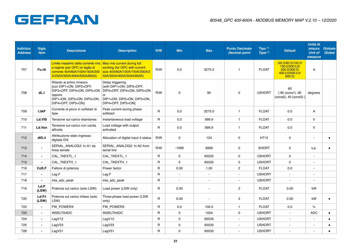
707 Fu.tA
Limite massimo della corrente rms a regime (per GPC on taglia di corrente 40A/60A/100A/150A/200A/250A/300A/400A/500A/600A)
Max rms current during full working (for GPC with current size 40A/60A/100A/150A/200A/250A/300A/400A/500A/600A)
R/W 0�0 3275�0 1 FLOAT
(40�0/60�0/100�0/150.0/200.Ł0/250�0/300�0/
400.Ł0/500.Ł0/600�0)
A
708 dL.t
Ritardo al primo innesco[con DIP1=ON, DIP2=OFF, DIP3=OFF, DIP4=ON, DIP5=ON oppureDIP1=ON, DIP2=ON, DIP3=ON, DIP4=OFF, DIP5=ON]
Delay triggering[with DIP1=ON, DIP2=OFF, DIP3=OFF, DIP4=ON, DIP5=ON orDIP1=ON, DIP2=ON, DIP3=ON, DIP4=OFF, DIP5=ON]
R/W 0 90 0 USHORT60
[ 90 (zona1), 90 (zona2), 40 (zona3) ]
degrees
709 I.tAP Corrente di picco in softstart di fase
Peak current during phase softstart R 0�0 3275�0 1 FLOAT 0�0 A
710 Ld.VIS Tensione sul carico istantanea Instantaneous load voltage R 0�0 999�9 1 FLOAT 0�0 V
711 Ld.Von Tensione sul carico con uscita attivata
Load voltage with output activated R 0�0 999�9 1 FLOAT 0�0 V
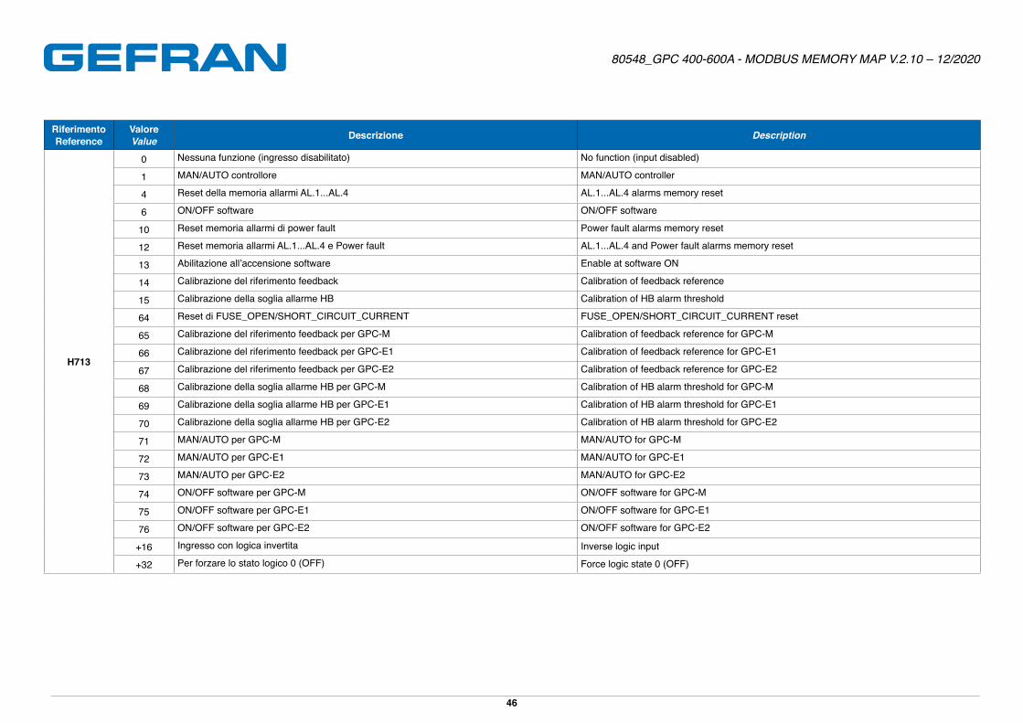
712 dIG.4 Attribuzione stato ingresso digitale DI4 Allocation of digital input 4 status R/W 0 124 0 H713 0 - ●
713 - SERIAL_ANALOG2: In.A1 da linea seriale
SERIAL_ANALOG2: In.A2 from serial line R/W -1999 9999 0 SHORT 0 s�p� ●
714 - CAL_TAEXTL_1 CAL_TAEXTL_1 R 0 65535 0 USHORT 0 -
715 - CAL_TAEXTH_1 CAL_TAEXTH_1 R 0 65535 0 USHORT 0 -
716 CoS.F Fattore di potenza Power factor R 0�00 1�00 2 FLOAT 0�0 -
717 - Lag.F Lag.F R - - - USHORT - -
718 - inta_adc_peak inta_adc_peak R - - - USHORT - -
719 Ld.P (LSW) Potenza sul carico (solo LSW) Load power (LSW only) R 0�00 - 2 FLOAT 0�00 kW
720 Ld.P.t (LSW)
Potenza sul carico trifase (solo LSW)
Three-phase load power (LSW only) R 0�00 - 2 FLOAT 0�00 kW ●
722 - FW_POWERX FW_POWERX R 0�0 100�0 1 FLOAT 0�0 %
723 - INSELTAADC INSELTAADC R 0 1024 0 USHORT - ADC ●
724 - LagV12 LagV12 R 0 65535 - USHORT - - ●
725 - LagV23 LagV23 R 0 65535 - USHORT - - ●
726 - LagV31 LagV31 R 0 65535 - USHORT - - ●
Page 22
80548_GPC 400-600A - MODBUS MEMORY MAP V.2.10 – 12/2020
22
IndirizzoAddress
SiglaItem Descrizione Description R/W Min Max Punto Decimale
Decimal pointTipo (1)
Type (1) Default
Unità di misuraUnit of
measure
GlobaleGlobal
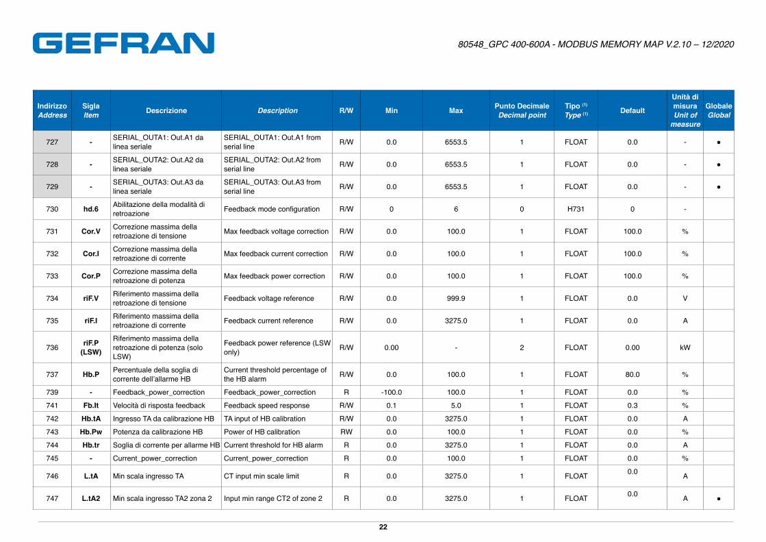
727 - SERIAL_OUTA1: Out.A1 da linea seriale
SERIAL_OUTA1: Out.A1 from serial line R/W 0�0 6553�5 1 FLOAT 0�0 - ●
728 - SERIAL_OUTA2: Out.A2 da linea seriale
SERIAL_OUTA2: Out.A2 from serial line R/W 0�0 6553�5 1 FLOAT 0�0 - ●
729 - SERIAL_OUTA3: Out.A3 da linea seriale
SERIAL_OUTA3: Out.A3 from serial line R/W 0�0 6553�5 1 FLOAT 0�0 - ●
730 hd.6 Abilitazione della modalità di retroazione Feedback mode configuration R/W 0 6 0 H731 0 -
731 Cor.V Correzione massima della retroazione di tensione Max feedback voltage correction R/W 0�0 100�0 1 FLOAT 100�0 %
732 Cor.I Correzione massima della retroazione di corrente Max feedback current correction R/W 0�0 100�0 1 FLOAT 100�0 %
733 Cor.P Correzione massima della retroazione di potenza Max feedback power correction R/W 0�0 100�0 1 FLOAT 100�0 %
734 riF.V Riferimento massima della retroazione di tensione Feedback voltage reference R/W 0�0 999�9 1 FLOAT 0�0 V
735 riF.I Riferimento massima della retroazione di corrente Feedback current reference R/W 0�0 3275�0 1 FLOAT 0�0 A
736 riF.P (LSW)
Riferimento massima della retroazione di potenza (solo LSW)
Feedback power reference (LSW only) R/W 0�00 - 2 FLOAT 0�00 kW
737 Hb.P Percentuale della soglia di corrente dell’allarme HB
Current threshold percentage of the HB alarm R/W 0�0 100�0 1 FLOAT 80�0 %
739 - Feedback_power_correction Feedback_power_correction R -100�0 100�0 1 FLOAT 0�0 %
741 Fb.It Velocità di risposta feedback Feedback speed response R/W 0�1 5�0 1 FLOAT 0�3 %
742 Hb.tA Ingresso TA da calibrazione HB TA input of HB calibration R/W 0�0 3275�0 1 FLOAT 0�0 A
743 Hb.Pw Potenza da calibrazione HB Power of HB calibration RW 0�0 100�0 1 FLOAT 0�0 %
744 Hb.tr Soglia di corrente per allarme HB Current threshold for HB alarm R 0�0 3275�0 1 FLOAT 0�0 A
745 - Current_power_correction Current_power_correction R 0�0 100�0 1 FLOAT 0�0 %
746 L.tA Min scala ingresso TA CT input min scale limit R 0�0 3275�0 1 FLOAT 0�0 A
747 L.tA2 Min scala ingresso TA2 zona 2 Input min range CT2 of zone 2 R 0�0 3275�0 1 FLOAT 0�0 A ●
Page 23
80548_GPC 400-600A - MODBUS MEMORY MAP V.2.10 – 12/2020
23
IndirizzoAddress
SiglaItem Descrizione Description R/W Min Max Punto Decimale
Decimal pointTipo (1)
Type (1) Default
Unità di misuraUnit of
measure
GlobaleGlobal
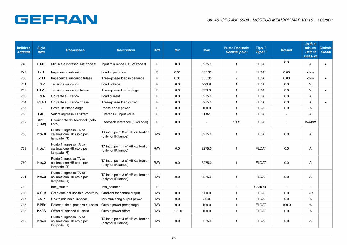
748 L.tA3 Min scala ingresso TA3 zona 3 Input min range CT3 of zone 3 R 0�0 3275�0 1 FLOAT 0�0 A ●
749 Ld.I Impedenza sul carico Load impedance R 0�00 655�35 2 FLOAT 0�00 ohm
750 Ld.I.t Impedenza sul carico trifase Three-phase load impedance R 0�00 655�35 2 FLOAT 0�00 ohm ●
751 Ld.V Tensione sul carico Load voltage R 0�0 999�9 1 FLOAT 0�0 V
752 Ld.V.t Tensione sul carico trifase Three-phase load voltage R 0�0 999�9 1 FLOAT 0�0 V ●
753 Ld.A Corrente sul carico Load current R 0�0 3275�0 1 FLOAT 0�0 A
754 Ld.A.t Corrente sul carico trifase Three-phase load current R 0�0 3275�0 1 FLOAT 0�0 A ●
755 - Power in Phase Angle Phase Angle power R 0�0 100�0 1 FLOAT 0�0 %
756 I.AF Valore ingresso TA filtrato Filtered CT input value R 0�0 H�tA1 1 FLOAT - A
757 AriF (LSW)
Riferimento del feedback (solo LSW) Feedback reference (LSW only) R 0�0 - 1/1/2 FLOAT 0 V/A/kW
758 Ir.tA.0Punto 0 ingresso TA da calibrazione HB (solo per lampade IR)
TA input point 0 of HB calibration (only for IR lamps) R/W 0�0 3275�0 1 FLOAT 0�0 A
759 Ir.tA.1Punto 1 ingresso TA da calibrazione HB (solo per lampade IR)
TA input point 1 of HB calibration (only for IR lamps) R/W 0�0 3275�0 1 FLOAT 0�0 A
760 Ir.tA.2Punto 2 ingresso TA da calibrazione HB (solo per lampade IR)
TA input point 2 of HB calibration (only for IR lamps) R/W 0�0 3275�0 1 FLOAT 0�0 A
761 Ir.tA.3Punto 3 ingresso TA da calibrazione HB (solo per lampade IR)
TA input point 3 of HB calibration (only for IR lamps) R/W 0�0 3275�0 1 FLOAT 0�0 A
762 - Inta_counter Inta_counter R - - 0 USHORT 0 -
763 G.Out Gradiente per uscita di controllo Gradient for control output R/W 0�0 200�0 1 FLOAT 0�0 %/s
764 Lo.P Uscita minima di innesco Minimun firing output power R/W 0�0 50�0 1 FLOAT 0�0 %
765 P.PEr Percentuale di potenza di uscita Output power percentage R/W 0�0 100�0 1 FLOAT 100�0 %
766 P.oFS Offset di potenza di uscita Output power offset R/W -100�0 100�0 1 FLOAT 0�0 %
767 Ir.tA.4Punto 4 ingresso TA da calibrazione HB (solo per lampade IR)
TA input point 4 of HB calibration (only for IR lamps) R/W 0�0 3275�0 1 FLOAT 0�0 A
Page 24
80548_GPC 400-600A - MODBUS MEMORY MAP V.2.10 – 12/2020
24
IndirizzoAddress
SiglaItem Descrizione Description R/W Min Max Punto Decimale
Decimal pointTipo (1)
Type (1) Default
Unità di misuraUnit of
measure
GlobaleGlobal
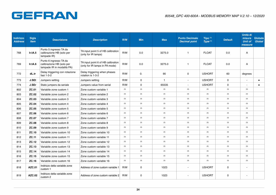
768 Ir.tA.5Punto 5 ingresso TA da calibrazione HB (solo per lampade IR)
TA input point 5 of HB calibration (only for IR lamps) R/W 0�0 3275�0 1 FLOAT 0�0 A
769 Ir.tA.6Punto 6 ingresso TA da calibrazione HB (solo per lampade IR in modalità PA)
TA input point 6 of HB calibration (only for IR lamps in PA mode) R/W 0�0 3275�0 1 FLOAT 0�0 A
772 dL.tr Delay triggering con rotazione fasi 1-3-2
Delay triggering when phases rotation is 1-3-2 R/W 0� 90 0 USHORT 60 degrees
773 J.SEt Jumpers setting Jumpers setting R/W 0 1 - USHORT 0 - ●
774 J.SEr Stato jumpers da seriale Jumpers value from serial R/W 0 65535 - USHORT 0 - ●
802 ZC.01 Variabile zone custom 1 Zone custom variable 1 (3) (3) (3) (3) (3) (3) (3)
803 ZC.02 Variabile zone custom 2 Zone custom variable 2 (3) (3) (3) (3) (3) (3) (3)
804 ZC.03 Variabile zone custom 3 Zone custom variable 3 (3) (3) (3) (3) (3) (3) (3)
805 ZC.04 Variabile zone custom 4 Zone custom variable 4 (3) (3) (3) (3) (3) (3) (3)
806 ZC.05 Variabile zone custom 5 Zone custom variable 5 (3) (3) (3) (3) (3) (3) (3)
807 ZC.06 Variabile zone custom 6 Zone custom variable 6 (3) (3) (3) (3) (3) (3) (3)
808 ZC.07 Variabile zone custom 7 Zone custom variable 7 (3) (3) (3) (3) (3) (3) (3)
809 ZC.08 Variabile zone custom 8 Zone custom variable 8 (3) (3) (3) (3) (3) (3) (3)
810 ZC.09 Variabile zone custom 9 Zone custom variable 9 (3) (3) (3) (3) (3) (3) (3)
811 ZC.10 Variabile zone custom 10 Zone custom variable 10 (3) (3) (3) (3) (3) (3) (3)
812 ZC.11 Variabile zone custom 11 Zone custom variable 11 (3) (3) (3) (3) (3) (3) (3)
813 ZC.12 Variabile zone custom 12 Zone custom variable 12 (3) (3) (3) (3) (3) (3) (3)
814 ZC.13 Variabile zone custom 13 Zone custom variable 13 (3) (3) (3) (3) (3) (3) (3)
815 ZC.14 Variabile zone custom 14 Zone custom variable 14 (3) (3) (3) (3) (3) (3) (3)
816 ZC.15 Variabile zone custom 15 Zone custom variable 15 (3) (3) (3) (3) (3) (3) (3)
817 ZC.16 Variabile zone custom 16 Zone custom variable 16 (3) (3) (3) (3) (3) (3) (3)
818 AZC.01 Indirizzo della variabile zone custom 1 Address of zone custom variable 1 R/W 0 1023 - USHORT 0 -
819 AZC.02 Indirizzo della variabile zone custom 2 Address of zone custom variable 2 R/W 0 1023 - USHORT 0 -
Page 25
80548_GPC 400-600A - MODBUS MEMORY MAP V.2.10 – 12/2020
25
IndirizzoAddress
SiglaItem Descrizione Description R/W Min Max Punto Decimale
Decimal pointTipo (1)
Type (1) Default
Unità di misuraUnit of
measure
GlobaleGlobal
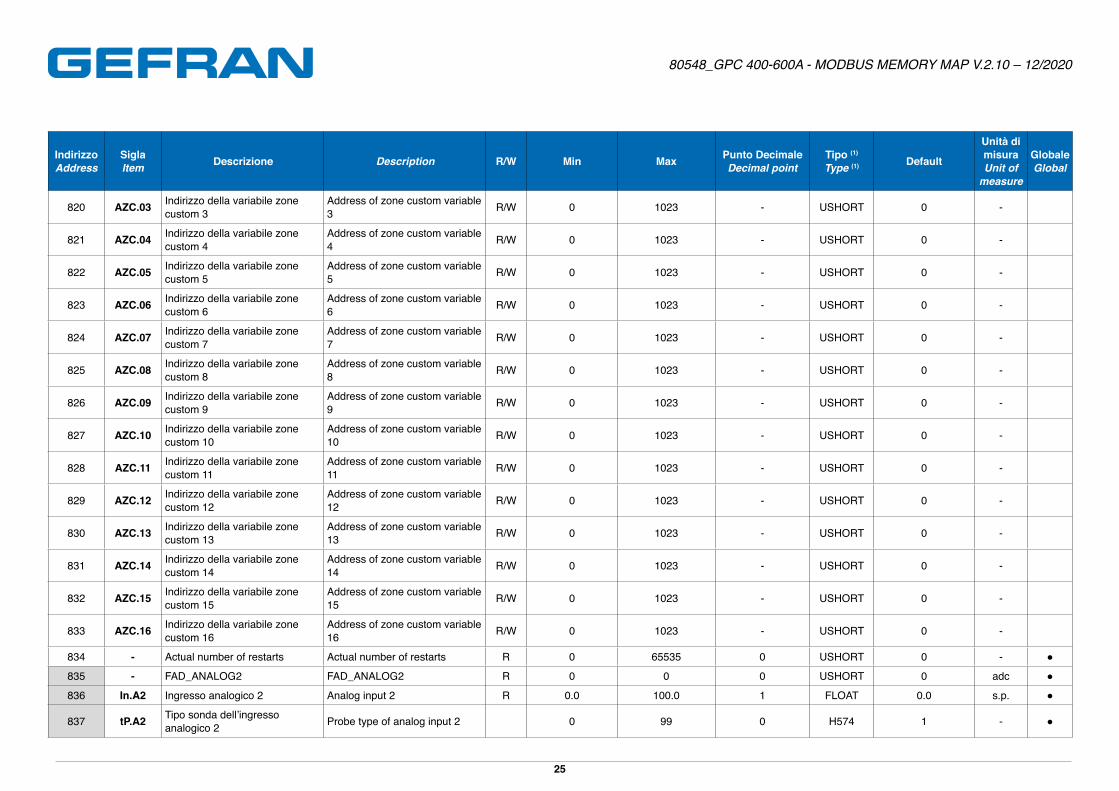
820 AZC.03 Indirizzo della variabile zone custom 3
Address of zone custom variable 3 R/W 0 1023 - USHORT 0 -
821 AZC.04 Indirizzo della variabile zone custom 4
Address of zone custom variable 4 R/W 0 1023 - USHORT 0 -
822 AZC.05 Indirizzo della variabile zone custom 5
Address of zone custom variable 5 R/W 0 1023 - USHORT 0 -
823 AZC.06 Indirizzo della variabile zone custom 6
Address of zone custom variable 6 R/W 0 1023 - USHORT 0 -
824 AZC.07 Indirizzo della variabile zone custom 7
Address of zone custom variable 7 R/W 0 1023 - USHORT 0 -
825 AZC.08 Indirizzo della variabile zone custom 8
Address of zone custom variable 8 R/W 0 1023 - USHORT 0 -
826 AZC.09 Indirizzo della variabile zone custom 9
Address of zone custom variable 9 R/W 0 1023 - USHORT 0 -
827 AZC.10 Indirizzo della variabile zone custom 10
Address of zone custom variable 10 R/W 0 1023 - USHORT 0 -
828 AZC.11 Indirizzo della variabile zone custom 11
Address of zone custom variable 11 R/W 0 1023 - USHORT 0 -
829 AZC.12 Indirizzo della variabile zone custom 12
Address of zone custom variable 12 R/W 0 1023 - USHORT 0 -
830 AZC.13 Indirizzo della variabile zone custom 13
Address of zone custom variable 13 R/W 0 1023 - USHORT 0 -
831 AZC.14 Indirizzo della variabile zone custom 14
Address of zone custom variable 14 R/W 0 1023 - USHORT 0 -
832 AZC.15 Indirizzo della variabile zone custom 15
Address of zone custom variable 15 R/W 0 1023 - USHORT 0 -
833 AZC.16 Indirizzo della variabile zone custom 16
Address of zone custom variable 16 R/W 0 1023 - USHORT 0 -
834 - Actual number of restarts Actual number of restarts R 0 65535 0 USHORT 0 - ●
835 - FAD_ANALOG2 FAD_ANALOG2 R 0 0 0 USHORT 0 adc ●
836 In.A2 Ingresso analogico 2 Analog input 2 R 0�0 100�0 1 FLOAT 0�0 s�p� ●
837 tP.A2 Tipo sonda dell’ingresso analogico 2 Probe type of analog input 2 0 99 0 H574 1 - ●
Page 26
80548_GPC 400-600A - MODBUS MEMORY MAP V.2.10 – 12/2020
26
IndirizzoAddress
SiglaItem Descrizione Description R/W Min Max Punto Decimale
Decimal pointTipo (1)
Type (1) Default
Unità di misuraUnit of
measure
GlobaleGlobal
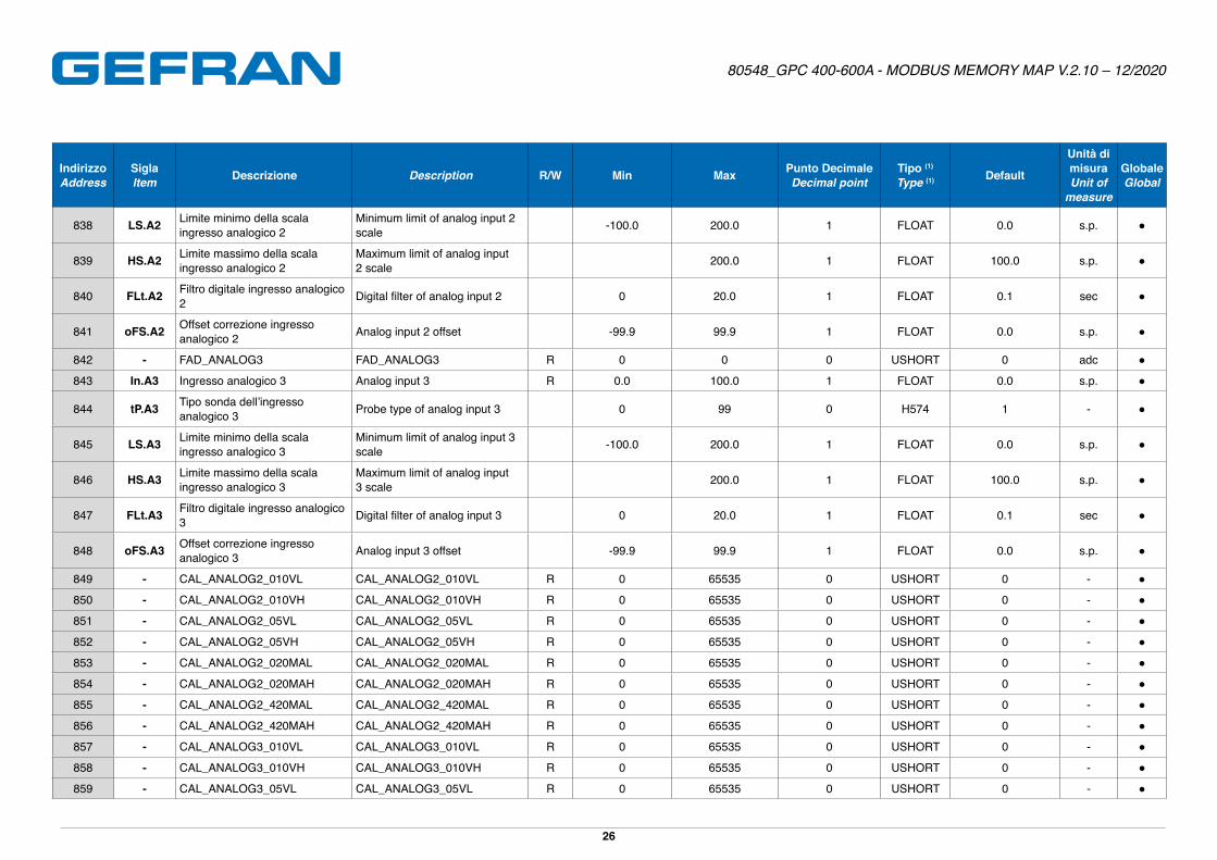
838 LS.A2 Limite minimo della scala ingresso analogico 2
Minimum limit of analog input 2 scale -100�0 200�0 1 FLOAT 0�0 s�p� ●
839 HS.A2 Limite massimo della scala ingresso analogico 2
Maximum limit of analog input 2 scale 200�0 1 FLOAT 100�0 s�p� ●
840 FLt.A2 Filtro digitale ingresso analogico 2 Digital filter of analog input 2 0 20�0 1 FLOAT 0�1 sec ●
841 oFS.A2 Offset correzione ingresso analogico 2 Analog input 2 offset -99�9 99�9 1 FLOAT 0�0 s�p� ●
842 - FAD_ANALOG3 FAD_ANALOG3 R 0 0 0 USHORT 0 adc ●
843 In.A3 Ingresso analogico 3 Analog input 3 R 0�0 100�0 1 FLOAT 0�0 s�p� ●
844 tP.A3 Tipo sonda dell’ingresso analogico 3 Probe type of analog input 3 0 99 0 H574 1 - ●
845 LS.A3 Limite minimo della scala ingresso analogico 3
Minimum limit of analog input 3 scale -100�0 200�0 1 FLOAT 0�0 s�p� ●
846 HS.A3 Limite massimo della scala ingresso analogico 3
Maximum limit of analog input 3 scale 200�0 1 FLOAT 100�0 s�p� ●
847 FLt.A3 Filtro digitale ingresso analogico 3 Digital filter of analog input 3 0 20�0 1 FLOAT 0�1 sec ●
848 oFS.A3 Offset correzione ingresso analogico 3 Analog input 3 offset -99�9 99�9 1 FLOAT 0�0 s�p� ●
849 - CAL_ANALOG2_010VL CAL_ANALOG2_010VL R 0 65535 0 USHORT 0 - ●
850 - CAL_ANALOG2_010VH CAL_ANALOG2_010VH R 0 65535 0 USHORT 0 - ●
851 - CAL_ANALOG2_05VL CAL_ANALOG2_05VL R 0 65535 0 USHORT 0 - ●
852 - CAL_ANALOG2_05VH CAL_ANALOG2_05VH R 0 65535 0 USHORT 0 - ●
853 - CAL_ANALOG2_020MAL CAL_ANALOG2_020MAL R 0 65535 0 USHORT 0 - ●
854 - CAL_ANALOG2_020MAH CAL_ANALOG2_020MAH R 0 65535 0 USHORT 0 - ●
855 - CAL_ANALOG2_420MAL CAL_ANALOG2_420MAL R 0 65535 0 USHORT 0 - ●
856 - CAL_ANALOG2_420MAH CAL_ANALOG2_420MAH R 0 65535 0 USHORT 0 - ●
857 - CAL_ANALOG3_010VL CAL_ANALOG3_010VL R 0 65535 0 USHORT 0 - ●
858 - CAL_ANALOG3_010VH CAL_ANALOG3_010VH R 0 65535 0 USHORT 0 - ●
859 - CAL_ANALOG3_05VL CAL_ANALOG3_05VL R 0 65535 0 USHORT 0 - ●
Page 27
80548_GPC 400-600A - MODBUS MEMORY MAP V.2.10 – 12/2020
27
IndirizzoAddress
SiglaItem Descrizione Description R/W Min Max Punto Decimale
Decimal pointTipo (1)
Type (1) Default
Unità di misuraUnit of
measure
GlobaleGlobal
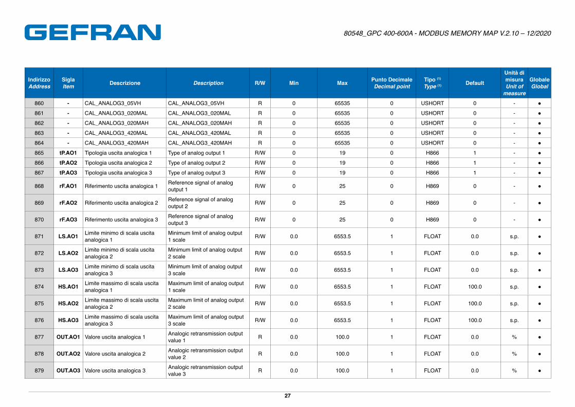
860 - CAL_ANALOG3_05VH CAL_ANALOG3_05VH R 0 65535 0 USHORT 0 - ●
861 - CAL_ANALOG3_020MAL CAL_ANALOG3_020MAL R 0 65535 0 USHORT 0 - ●
862 - CAL_ANALOG3_020MAH CAL_ANALOG3_020MAH R 0 65535 0 USHORT 0 - ●
863 - CAL_ANALOG3_420MAL CAL_ANALOG3_420MAL R 0 65535 0 USHORT 0 - ●
864 - CAL_ANALOG3_420MAH CAL_ANALOG3_420MAH R 0 65535 0 USHORT 0 - ●
865 tP.AO1 Tipologia uscita analogica 1 Type of analog output 1 R/W 0 19 0 H866 1 - ●
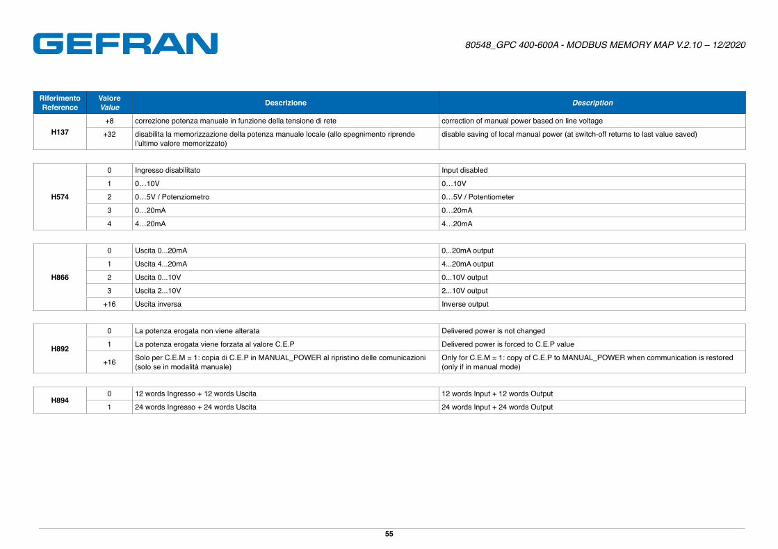
866 tP.AO2 Tipologia uscita analogica 2 Type of analog output 2 R/W 0 19 0 H866 1 - ●
867 tP.AO3 Tipologia uscita analogica 3 Type of analog output 3 R/W 0 19 0 H866 1 - ●
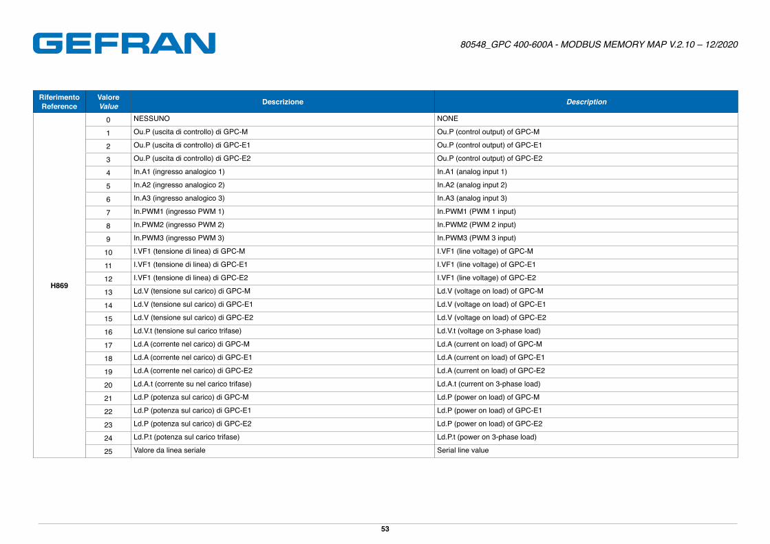
868 rF.AO1 Riferimento uscita analogica 1 Reference signal of analog output 1 R/W 0 25 0 H869 0 - ●
869 rF.AO2 Riferimento uscita analogica 2 Reference signal of analog output 2 R/W 0 25 0 H869 0 - ●
870 rF.AO3 Riferimento uscita analogica 3 Reference signal of analog output 3 R/W 0 25 0 H869 0 - ●
871 LS.AO1 Limite minimo di scala uscita analogica 1
Minimum limit of analog output 1 scale R/W 0�0 6553�5 1 FLOAT 0�0 s�p� ●
872 LS.AO2 Limite minimo di scala uscita analogica 2
Minimum limit of analog output 2 scale R/W 0�0 6553�5 1 FLOAT 0�0 s�p� ●
873 LS.AO3 Limite minimo di scala uscita analogica 3
Minimum limit of analog output 3 scale R/W 0�0 6553�5 1 FLOAT 0�0 s�p� ●
874 HS.AO1 Limite massimo di scala uscita analogica 1
Maximum limit of analog output 1 scale R/W 0�0 6553�5 1 FLOAT 100�0 s�p� ●
875 HS.AO2 Limite massimo di scala uscita analogica 2
Maximum limit of analog output 2 scale R/W 0�0 6553�5 1 FLOAT 100�0 s�p� ●
876 HS.AO3 Limite massimo di scala uscita analogica 3
Maximum limit of analog output 3 scale R/W 0�0 6553�5 1 FLOAT 100�0 s�p� ●
877 OUT.AO1 Valore uscita analogica 1 Analogic retransmission output value 1 R 0�0 100�0 1 FLOAT 0�0 % ●
878 OUT.AO2 Valore uscita analogica 2 Analogic retransmission output value 2 R 0�0 100�0 1 FLOAT 0�0 % ●
879 OUT.AO3 Valore uscita analogica 3 Analogic retransmission output value 3 R 0�0 100�0 1 FLOAT 0�0 % ●
Page 28
80548_GPC 400-600A - MODBUS MEMORY MAP V.2.10 – 12/2020
28
IndirizzoAddress
SiglaItem Descrizione Description R/W Min Max Punto Decimale
Decimal pointTipo (1)
Type (1) Default
Unità di misuraUnit of
measure
GlobaleGlobal
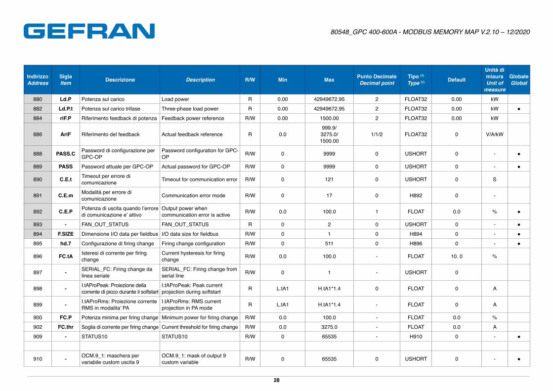
880 Ld.P Potenza sul carico Load power R 0�00 42949672�95 2 FLOAT32 0�00 kW
882 Ld.P.t Potenza sul carico trifase Three-phase load power R 0�00 42949672�95 2 FLOAT32 0�00 kW ●
884 riF.P Riferimento feedback di potenza Feedback power reference R/W 0�00 1500�00 2 FLOAT32 0�00 kW
886 AriF Riferimento del feedback Actual feedback reference R 0�0999�9/3275�0/1500�00
1/1/2 FLOAT32 0 V/A/kW
888 PASS.C Password di configurazione per GPC-OP
Password configuration for GPC-OP R/W 0 9999 0 USHORT 0 - ●
889 PASS Password attuale per GPC-OP Actual password for GPC-OP R/W 0 9999 0 USHORT 0 - ●
890 C.E.t Timeout per errore di comunicazione Timeout for communication error R/W 0 121 0 USHORT 0 S
891 C.E.m Modalità per errore di comunicazione Communication error mode R/W 0 17 0 H892 0 -
892 C.E.P Potenza di uscita quando l’errore di comunicazione e’ attivo
Output power when communication error is active R/W 0�0 100�0 1 FLOAT 0�0 % ●
893 - FAN_OUT_STATUS FAN_OUT_STATUS R 0 2 0 USHORT 0 - ●
894 F.SIZE Dimensione I/O data per fieldbus I/O data size for fieldbus R/W 0 1 0 H894 0 - ●
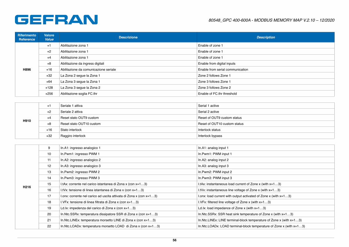
895 hd.7 Configurazione di firing change Firing change configuration R/W 0 511 0 H896 0 - ●
896 FC.tA Isteresi di corrente per firing change
Current hysteresis for firing change R/W 0�0 100�0 - FLOAT 10� 0 %
897 - SERIAL_FC: Firing change da linea seriale
SERIAL_FC: Firing change from serial line R/W 0 1 - USHORT 0
898 - I.tAProPeak: Proiezione della corrente di picco durante il softstart
I.tAProPeak: Peak current projection during softstart R L�tA1 H�tA1*1�4 0 FLOAT 0 A
899 - I.tAProRms: Proiezione corrente RMS in modalita’ PA
I.tAProRms: RMS current projection in PA mode R L�tA1 H�tA1*1�4 - FLOAT 0 A
900 FC.P Potenza minima per firing change Minimum power for firing change R/W 0�0 100�0 - FLOAT 0�0 %
902 FC.thr Soglia di corrente per firing change Current threshold for firing change R/W 0�0 3275�0 - FLOAT 0�0 A
909 - STATUS10 STATUS10 R/W 0 65535 - H910 0 - ●
910 - OCM.9_1: maschera per variabile custom uscita 9
OCM.9_1: mask of output 9 custom variable R/W 0 65535 0 USHORT 0 - ●
Page 29
80548_GPC 400-600A - MODBUS MEMORY MAP V.2.10 – 12/2020
29
IndirizzoAddress
SiglaItem Descrizione Description R/W Min Max Punto Decimale
Decimal pointTipo (1)
Type (1) Default
Unità di misuraUnit of
measure
GlobaleGlobal
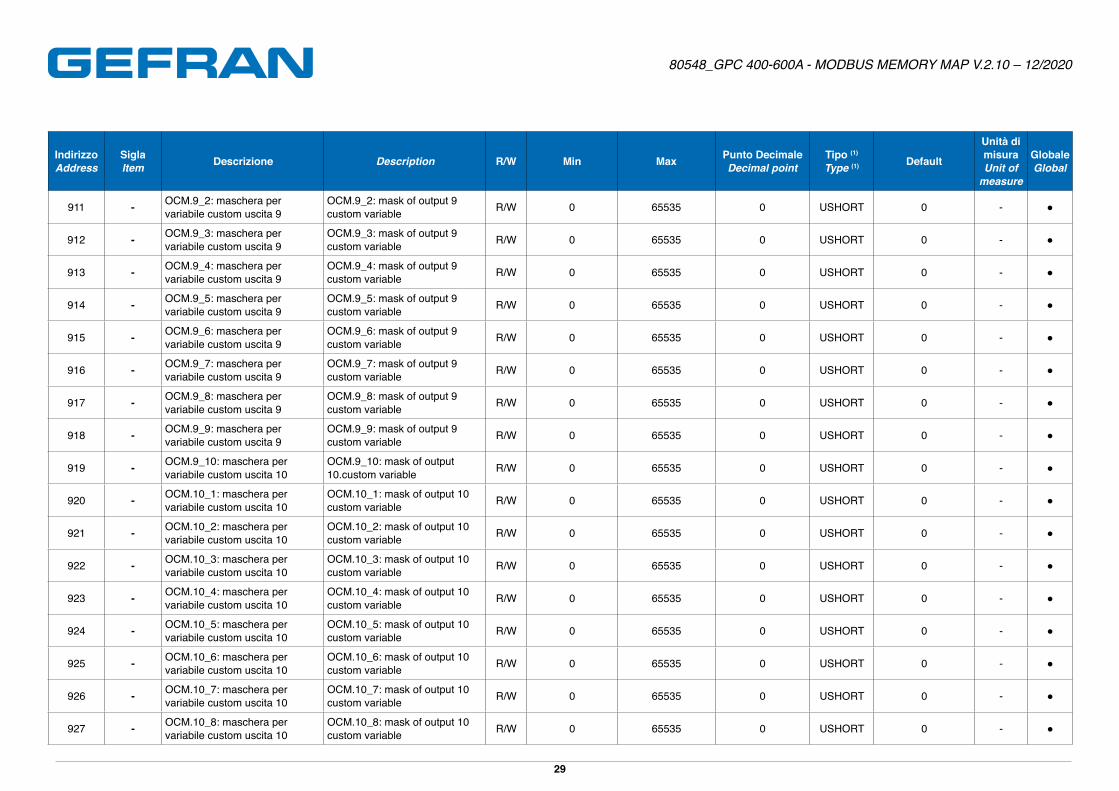
911 - OCM.9_2: maschera per variabile custom uscita 9
OCM.9_2: mask of output 9 custom variable R/W 0 65535 0 USHORT 0 - ●
912 - OCM.9_3: maschera per variabile custom uscita 9
OCM.9_3: mask of output 9 custom variable R/W 0 65535 0 USHORT 0 - ●
913 - OCM.9_4: maschera per variabile custom uscita 9
OCM.9_4: mask of output 9 custom variable R/W 0 65535 0 USHORT 0 - ●
914 - OCM.9_5: maschera per variabile custom uscita 9
OCM.9_5: mask of output 9 custom variable R/W 0 65535 0 USHORT 0 - ●
915 - OCM.9_6: maschera per variabile custom uscita 9
OCM.9_6: mask of output 9 custom variable R/W 0 65535 0 USHORT 0 - ●
916 - OCM.9_7: maschera per variabile custom uscita 9
OCM.9_7: mask of output 9 custom variable R/W 0 65535 0 USHORT 0 - ●
917 - OCM.9_8: maschera per variabile custom uscita 9
OCM.9_8: mask of output 9 custom variable R/W 0 65535 0 USHORT 0 - ●
918 - OCM.9_9: maschera per variabile custom uscita 9
OCM.9_9: mask of output 9 custom variable R/W 0 65535 0 USHORT 0 - ●
919 - OCM.9_10: maschera per variabile custom uscita 10
OCM.9_10: mask of output 10�custom variable R/W 0 65535 0 USHORT 0 - ●
920 - OCM.10_1: maschera per variabile custom uscita 10
OCM.10_1: mask of output 10 custom variable R/W 0 65535 0 USHORT 0 - ●
921 - OCM.10_2: maschera per variabile custom uscita 10
OCM.10_2: mask of output 10 custom variable R/W 0 65535 0 USHORT 0 - ●
922 - OCM.10_3: maschera per variabile custom uscita 10
OCM.10_3: mask of output 10 custom variable R/W 0 65535 0 USHORT 0 - ●
923 - OCM.10_4: maschera per variabile custom uscita 10
OCM.10_4: mask of output 10 custom variable R/W 0 65535 0 USHORT 0 - ●
924 - OCM.10_5: maschera per variabile custom uscita 10
OCM.10_5: mask of output 10 custom variable R/W 0 65535 0 USHORT 0 - ●
925 - OCM.10_6: maschera per variabile custom uscita 10
OCM.10_6: mask of output 10 custom variable R/W 0 65535 0 USHORT 0 - ●
926 - OCM.10_7: maschera per variabile custom uscita 10
OCM.10_7: mask of output 10 custom variable R/W 0 65535 0 USHORT 0 - ●
927 - OCM.10_8: maschera per variabile custom uscita 10
OCM.10_8: mask of output 10 custom variable R/W 0 65535 0 USHORT 0 - ●
Page 30
80548_GPC 400-600A - MODBUS MEMORY MAP V.2.10 – 12/2020
30
IndirizzoAddress
SiglaItem Descrizione Description R/W Min Max Punto Decimale
Decimal pointTipo (1)
Type (1) Default
Unità di misuraUnit of
measure
GlobaleGlobal
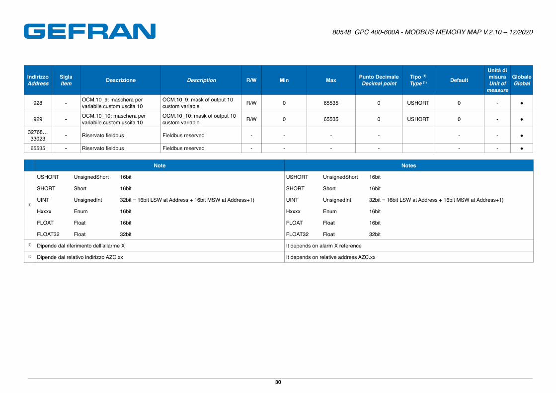
928 - OCM.10_9: maschera per variabile custom uscita 10
OCM.10_9: mask of output 10 custom variable R/W 0 65535 0 USHORT 0 - ●
929 - OCM.10_10: maschera per variabile custom uscita 10
OCM.10_10: mask of output 10 custom variable R/W 0 65535 0 USHORT 0 - ●
32768…33023 - Riservato fieldbus Fieldbus reserved - - - - - - ●
65535 - Riservato fieldbus Fieldbus reserved - - - - - - ●
Note Notes
(1)
USHORT UnsignedShort 16bit USHORT UnsignedShort 16bit
SHORT Short 16bit SHORT Short 16bit
UINT UnsignedInt 32bit = 16bit LSW at Address + 16bit MSW at Address+1) UINT UnsignedInt 32bit = 16bit LSW at Address + 16bit MSW at Address+1)
Hxxxx Enum 16bit Hxxxx Enum 16bit
FLOAT Float 16bit FLOAT Float 16bit
FLOAT32 Float 32bit FLOAT32 Float 32bit
(2) Dipende dal riferimento dell’allarme X It depends on alarm X reference
(3) Dipende dal relativo indirizzo AZC.xx It depends on relative address AZC.xx
Page 31
80548_GPC 400-600A - MODBUS MEMORY MAP V.2.10 – 12/2020
31
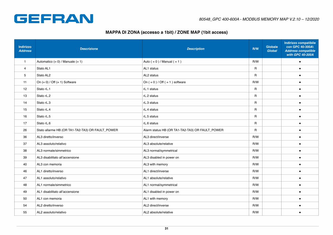
MAPPA DI ZONA (accesso a 1bit) / ZONE MAP (1bit access)
IndirizzoAddress Descrizione Description R/W Globale
Global
Indirizzo compatibile con GPC 40-300A\
Address compatible with GPC 40-300A
1 Automatico (= 0) / Manuale (= 1) Auto ( = 0 ) / Manual ( = 1 ) R/W ●
4 Stato AL1 AL1 status R ●
5 Stato AL2 AL2 status R ●
11 On (= 0) / Off (= 1) Software On ( = 0 ) / Off ( = 1 ) software R/W ●
12 Stato rL�1 rL�1 status R ●
13 Stato rL�2 rL�2 status R ●
14 Stato rL�3 rL�3 status R ●
15 Stato rL�4 rL�4 status R ●
16 Stato rL�5 rL�5 status R ●
17 Stato rL�6 rL�6 status R ●
26 Stato allarme HB (OR TA1-TA2-TA3) OR FAULT_POWER Alarm status HB (OR TA1-TA2-TA3) OR FAULT_POWER R ●
36 AL3 diretto/inverso AL3 direct/inverse R/W ●
37 AL3 assoluto/relativo AL3 absolute/relative R/W ●
38 AL3 normale/simmetrico AL3 normal/symmetrical R/W ●
39 AL3 disabilitato all’accensione AL3 disabled in power on R/W ●
40 AL3 con memoria AL3 with memory R/W ●
46 AL1 diretto/inverso AL1 direct/inverse R/W ●
47 AL1 assoluto/relativo AL1 absolute/relative R/W ●
48 AL1 normale/simmetrico AL1 normal/symmetrical R/W ●
49 AL1 disabilitato all’accensione AL1 disabled in power on R/W ●
50 AL1 con memoria AL1 with memory R/W ●
54 AL2 diretto/inverso AL2 direct/inverse R/W ●
55 AL2 assoluto/relativo AL2 absolute/relative R/W ●
Page 32
80548_GPC 400-600A - MODBUS MEMORY MAP V.2.10 – 12/2020
32
IndirizzoAddress Descrizione Description R/W Globale
Global
Indirizzo compatibile con GPC 40-300A\
Address compatible with GPC 40-300A
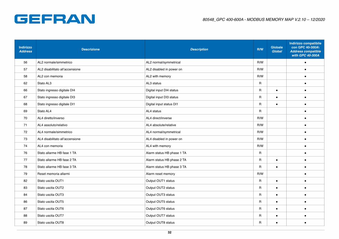
56 AL2 normale/simmetrico AL2 normal/symmetrical R/W ●
57 AL2 disabilitato all’accensione AL2 disabled in power on R/W ●
58 AL2 con memoria AL2 with memory R/W ●
62 Stato AL3 AL3 status R ●
66 Stato ingresso digitale DI4 Digital input DI4 status R ● ●
67 Stato ingresso digitale DI3 Digital input DI3 status R ● ●
68 Stato ingresso digitale DI1 Digital input status DI1 R ● ●
69 Stato AL4 AL4 status R ●
70 AL4 diretto/inverso AL4 direct/inverse R/W ●
71 AL4 assoluto/relativo AL4 absolute/relative R/W ●
72 AL4 normale/simmetrico AL4 normal/symmetrical R/W ●
73 AL4 disabilitato all’accensione AL4 disabled in power on R/W ●
74 AL4 con memoria AL4 with memory R/W ●
76 Stato allarme HB fase 1 TA Alarm status HB phase 1 TA R ●
77 Stato allarme HB fase 2 TA Alarm status HB phase 2 TA R ● ●
78 Stato allarme HB fase 3 TA Alarm status HB phase 3 TA R ● ●
79 Reset memoria allarmi Alarm reset memory R/W ●
82 Stato uscita OUT1 Output OUT1 status R ● ●
83 Stato uscita OUT2 Output OUT2 status R ● ●
84 Stato uscita OUT3 Output OUT3 status R ● ●
86 Stato uscita OUT5 Output OUT5 status R ● ●
87 Stato uscita OUT6 Output OUT6 status R ● ●
88 Stato uscita OUT7 Output OUT7 status R ● ●
89 Stato uscita OUT8 Output OUT8 status R ● ●
Page 33
80548_GPC 400-600A - MODBUS MEMORY MAP V.2.10 – 12/2020
33
IndirizzoAddress Descrizione Description R/W Globale
Global
Indirizzo compatibile con GPC 40-300A\
Address compatible with GPC 40-300A
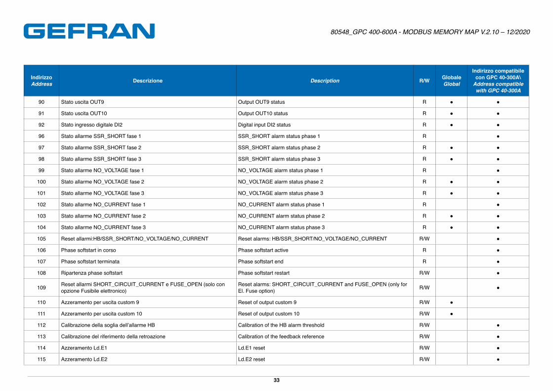
90 Stato uscita OUT9 Output OUT9 status R ● ●
91 Stato uscita OUT10 Output OUT10 status R ● ●
92 Stato ingresso digitale DI2 Digital input DI2 status R ● ●
96 Stato allarme SSR_SHORT fase 1 SSR_SHORT alarm status phase 1 R ●
97 Stato allarme SSR_SHORT fase 2 SSR_SHORT alarm status phase 2 R ● ●
98 Stato allarme SSR_SHORT fase 3 SSR_SHORT alarm status phase 3 R ● ●
99 Stato allarme NO_VOLTAGE fase 1 NO_VOLTAGE alarm status phase 1 R ●
100 Stato allarme NO_VOLTAGE fase 2 NO_VOLTAGE alarm status phase 2 R ● ●
101 Stato allarme NO_VOLTAGE fase 3 NO_VOLTAGE alarm status phase 3 R ● ●
102 Stato allarme NO_CURRENT fase 1 NO_CURRENT alarm status phase 1 R ●
103 Stato allarme NO_CURRENT fase 2 NO_CURRENT alarm status phase 2 R ● ●
104 Stato allarme NO_CURRENT fase 3 NO_CURRENT alarm status phase 3 R ● ●
105 Reset allarmi:HB/SSR_SHORT/NO_VOLTAGE/NO_CURRENT Reset alarms: HB/SSR_SHORT/NO_VOLTAGE/NO_CURRENT R/W ●
106 Phase softstart in corso Phase softstart active R ●
107 Phase softstart terminata Phase softstart end R ●
108 Ripartenza phase softstart Phase softstart restart R/W ●
109 Reset allarmi SHORT_CIRCUIT_CURRENT e FUSE_OPEN (solo con opzione Fusibile elettronico)
Reset alarms: SHORT_CIRCUIT_CURRENT and FUSE_OPEN (only for El� Fuse option) R/W ●
110 Azzeramento per uscita custom 9 Reset of output custom 9 R/W ●
111 Azzeramento per uscita custom 10 Reset of output custom 10 R/W ●
112 Calibrazione della soglia dell’allarme HB Calibration of the HB alarm threshold R/W ●
113 Calibrazione del riferimento della retroazione Calibration of the feedback reference R/W ●
114 Azzeramento Ld�E1 Ld�E1 reset R/W ●
115 Azzeramento Ld�E2 Ld�E2 reset R/W ●
Page 34
80548_GPC 400-600A - MODBUS MEMORY MAP V.2.10 – 12/2020
34
IndirizzoAddress Descrizione Description R/W Globale
Global
Indirizzo compatibile con GPC 40-300A\
Address compatible with GPC 40-300A
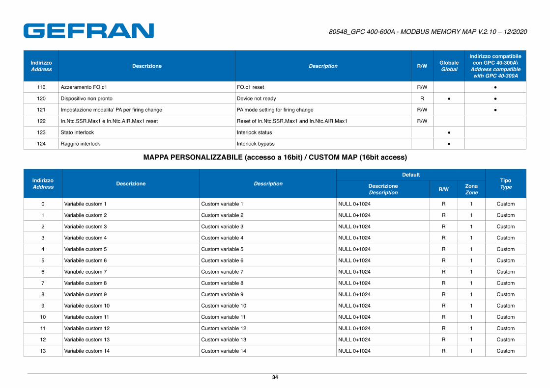
116 Azzeramento FO�c1 FO�c1 reset R/W ●
120 Dispositivo non pronto Device not ready R ● ●
121 Impostazione modalita’ PA per firing change PA mode setting for firing change R/W ●
122 In.Ntc.SSR.Max1 e In.Ntc.AIR.Max1 reset Reset of In.Ntc.SSR.Max1 and In.Ntc.AIR.Max1 R/W
123 Stato interlock Interlock status ●
124 Raggiro interlock Interlock bypass ●
MAPPA PERSONALIZZABILE (accesso a 16bit) / CUSTOM MAP (16bit access)
IndirizzoAddress Descrizione Description
DefaultTipoTypeDescrizione
Description R/W ZonaZone
0 Variabile custom 1 Custom variable 1 NULL 0+1024 R 1 Custom
1 Variabile custom 2 Custom variable 2 NULL 0+1024 R 1 Custom
2 Variabile custom 3 Custom variable 3 NULL 0+1024 R 1 Custom
3 Variabile custom 4 Custom variable 4 NULL 0+1024 R 1 Custom
4 Variabile custom 5 Custom variable 5 NULL 0+1024 R 1 Custom
5 Variabile custom 6 Custom variable 6 NULL 0+1024 R 1 Custom
6 Variabile custom 7 Custom variable 7 NULL 0+1024 R 1 Custom
7 Variabile custom 8 Custom variable 8 NULL 0+1024 R 1 Custom
8 Variabile custom 9 Custom variable 9 NULL 0+1024 R 1 Custom
9 Variabile custom 10 Custom variable 10 NULL 0+1024 R 1 Custom
10 Variabile custom 11 Custom variable 11 NULL 0+1024 R 1 Custom
11 Variabile custom 12 Custom variable 12 NULL 0+1024 R 1 Custom
12 Variabile custom 13 Custom variable 13 NULL 0+1024 R 1 Custom
13 Variabile custom 14 Custom variable 14 NULL 0+1024 R 1 Custom
Page 35
80548_GPC 400-600A - MODBUS MEMORY MAP V.2.10 – 12/2020
35
IndirizzoAddress Descrizione Description
DefaultTipoTypeDescrizione
Description R/W ZonaZone
14 Variabile custom 15 Custom variable 15 NULL 0+1024 R 1 Custom
15 Variabile custom 16 Custom variable 16 NULL 0+1024 R 1 Custom
16 Variabile custom 17 Custom variable 17 NULL 0+1024 R 1 Custom
17 Variabile custom 18 Custom variable 18 NULL 0+1024 R 1 Custom
18 Variabile custom 19 Custom variable 19 NULL 0+1024 R 1 Custom
19 Variabile custom 20 Custom variable 20 NULL 0+1024 R 1 Custom
20 Variabile custom 21 Custom variable 21 NULL 0+1024 R 1 Custom
21 Variabile custom 22 Custom variable 22 NULL 0+1024 R 1 Custom
22 Variabile custom 23 Custom variable 23 NULL 0+1024 R 1 Custom
23 Variabile custom 24 Custom variable 24 NULL 0+1024 R 1 Custom
24 Variabile custom 25 Custom variable 25 NULL 0+1024 R 1 Custom
25 Variabile custom 26 Custom variable 26 NULL 0+1024 R 1 Custom
26 Variabile custom 27 Custom variable 27 NULL 0+1024 R 1 Custom
27 Variabile custom 28 Custom variable 28 NULL 0+1024 R 1 Custom
28 Variabile custom 29 Custom variable 29 NULL 0+1024 R 1 Custom
29 Variabile custom 30 Custom variable 30 NULL 0+1024 R 1 Custom
30 Variabile custom 31 Custom variable 31 NULL 0+1024 R 1 Custom
31 Variabile custom 32 Custom variable 32 NULL 0+1024 R 1 Custom
32 Variabile custom 33 Custom variable 33 NULL 0+1024 R 1 Custom
33 Variabile custom 34 Custom variable 34 NULL 0+1024 R 1 Custom
34 Variabile custom 35 Custom variable 35 NULL 0+1024 R 1 Custom
35 Variabile custom 36 Custom variable 36 NULL 0+1024 R 1 Custom
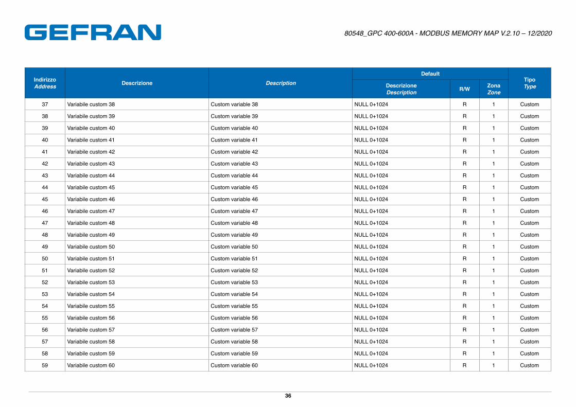
36 Variabile custom 37 Custom variable 37 NULL 0+1024 R 1 Custom
Page 36
80548_GPC 400-600A - MODBUS MEMORY MAP V.2.10 – 12/2020
36
IndirizzoAddress Descrizione Description
DefaultTipoTypeDescrizione
Description R/W ZonaZone
37 Variabile custom 38 Custom variable 38 NULL 0+1024 R 1 Custom
38 Variabile custom 39 Custom variable 39 NULL 0+1024 R 1 Custom
39 Variabile custom 40 Custom variable 40 NULL 0+1024 R 1 Custom
40 Variabile custom 41 Custom variable 41 NULL 0+1024 R 1 Custom
41 Variabile custom 42 Custom variable 42 NULL 0+1024 R 1 Custom
42 Variabile custom 43 Custom variable 43 NULL 0+1024 R 1 Custom
43 Variabile custom 44 Custom variable 44 NULL 0+1024 R 1 Custom
44 Variabile custom 45 Custom variable 45 NULL 0+1024 R 1 Custom
45 Variabile custom 46 Custom variable 46 NULL 0+1024 R 1 Custom
46 Variabile custom 47 Custom variable 47 NULL 0+1024 R 1 Custom
47 Variabile custom 48 Custom variable 48 NULL 0+1024 R 1 Custom
48 Variabile custom 49 Custom variable 49 NULL 0+1024 R 1 Custom
49 Variabile custom 50 Custom variable 50 NULL 0+1024 R 1 Custom
50 Variabile custom 51 Custom variable 51 NULL 0+1024 R 1 Custom
51 Variabile custom 52 Custom variable 52 NULL 0+1024 R 1 Custom
52 Variabile custom 53 Custom variable 53 NULL 0+1024 R 1 Custom
53 Variabile custom 54 Custom variable 54 NULL 0+1024 R 1 Custom
54 Variabile custom 55 Custom variable 55 NULL 0+1024 R 1 Custom
55 Variabile custom 56 Custom variable 56 NULL 0+1024 R 1 Custom
56 Variabile custom 57 Custom variable 57 NULL 0+1024 R 1 Custom
57 Variabile custom 58 Custom variable 58 NULL 0+1024 R 1 Custom
58 Variabile custom 59 Custom variable 59 NULL 0+1024 R 1 Custom
59 Variabile custom 60 Custom variable 60 NULL 0+1024 R 1 Custom
Page 37
80548_GPC 400-600A - MODBUS MEMORY MAP V.2.10 – 12/2020
37
IndirizzoAddress Descrizione Description
DefaultTipoTypeDescrizione
Description R/W ZonaZone
60 Variabile custom 61 Custom variable 61 NULL 0+1024 R 1 Custom
61 Variabile custom 62 Custom variable 62 NULL 0+1024 R 1 Custom
62 Variabile custom 63 Custom variable 63 NULL 0+1024 R 1 Custom
63 Variabile custom 64 Custom variable 64 NULL 0+1024 R 1 Custom
64 Variabile custom 65 Custom variable 65 NULL 0+1024 R 1 Custom
65 Variabile custom 66 Custom variable 66 NULL 0+1024 R 1 Custom
66 Variabile custom 67 Custom variable 67 NULL 0+1024 R 1 Custom
67 Variabile custom 68 Custom variable 68 NULL 0+1024 R 1 Custom
68 Variabile custom 69 Custom variable 69 NULL 0+1024 R 1 Custom
69 Variabile custom 70 Custom variable 70 NULL 0+1024 R 1 Custom
70 Variabile custom 71 Custom variable 71 NULL 0+1024 R 1 Custom
71 Variabile custom 72 Custom variable 72 NULL 0+1024 R 1 Custom
72 Variabile custom 73 Custom variable 73 NULL 0+1024 R 1 Custom
73 Variabile custom 74 Custom variable 74 NULL 0+1024 R 1 Custom
74 Variabile custom 75 Custom variable 75 NULL 0+1024 R 1 Custom
75 Variabile custom 76 Custom variable 76 NULL 0+1024 R 1 Custom
76 Variabile custom 77 Custom variable 77 NULL 0+1024 R 1 Custom
77 Variabile custom 78 Custom variable 78 NULL 0+1024 R 1 Custom
78 Variabile custom 79 Custom variable 79 NULL 0+1024 R 1 Custom
79 Variabile custom 80 Custom variable 80 NULL 0+1024 R 1 Custom
80 Variabile custom 81 Custom variable 81 NULL 0+1024 R 1 Custom
81 Variabile custom 82 Custom variable 82 NULL 0+1024 R 1 Custom
82 Variabile custom 83 Custom variable 83 NULL 0+1024 R 1 Custom
Page 38
80548_GPC 400-600A - MODBUS MEMORY MAP V.2.10 – 12/2020
38
IndirizzoAddress Descrizione Description
DefaultTipoTypeDescrizione
Description R/W ZonaZone
83 Variabile custom 84 Custom variable 84 NULL 0+1024 R 1 Custom
84 Variabile custom 85 Custom variable 85 NULL 0+1024 R 1 Custom
85 Variabile custom 86 Custom variable 86 NULL 0+1024 R 1 Custom
86 Variabile custom 87 Custom variable 87 NULL 0+1024 R 1 Custom
87 Variabile custom 88 Custom variable 88 NULL 0+1024 R 1 Custom
88 Variabile custom 89 Custom variable 89 NULL 0+1024 R 1 Custom
89 Variabile custom 90 Custom variable 90 NULL 0+1024 R 1 Custom
90 Variabile custom 91 Custom variable 91 NULL 0+1024 R 1 Custom
91 Variabile custom 92 Custom variable 92 NULL 0+1024 R 1 Custom
92 Variabile custom 93 Custom variable 93 NULL 0+1024 R 1 Custom
93 Variabile custom 94 Custom variable 94 NULL 0+1024 R 1 Custom
94 Variabile custom 95 Custom variable 95 NULL 0+1024 R 1 Custom
95 Variabile custom 96 Custom variable 96 NULL 0+1024 R 1 Custom
96 Variabile custom 97 Custom variable 97 NULL 0+1024 R 1 Custom
97 Variabile custom 98 Custom variable 98 NULL 0+1024 R 1 Custom
98 Variabile custom 99 Custom variable 99 NULL 0+1024 R 1 Custom
99 Variabile custom 100 Custom variable 100 NULL 0+1024 R 1 Custom
100 Variabile custom 101 Custom variable 101 NULL 0+1024 R 1 Custom
101 Variabile custom 102 Custom variable 102 NULL 0+1024 R 1 Custom
102 Variabile custom 103 Custom variable 103 NULL 0+1024 R 1 Custom
103 Variabile custom 104 Custom variable 104 NULL 0+1024 R 1 Custom
104 Variabile custom 105 Custom variable 105 NULL 0+1024 R 1 Custom
105 Variabile custom 106 Custom variable 106 NULL 0+1024 R 1 Custom
Page 39
80548_GPC 400-600A - MODBUS MEMORY MAP V.2.10 – 12/2020
39
IndirizzoAddress Descrizione Description
DefaultTipoTypeDescrizione
Description R/W ZonaZone
106 Variabile custom 107 Custom variable 107 NULL 0+1024 R 1 Custom
107 Variabile custom 108 Custom variable 108 NULL 0+1024 R 1 Custom
108 Variabile custom 109 Custom variable 109 NULL 0+1024 R 1 Custom
109 Variabile custom 110 Custom variable 110 NULL 0+1024 R 1 Custom
110 Variabile custom 111 Custom variable 111 NULL 0+1024 R 1 Custom
111 Variabile custom 112 Custom variable 112 NULL 0+1024 R 1 Custom
112 Variabile custom 113 Custom variable 113 NULL 0+1024 R 1 Custom
113 Variabile custom 114 Custom variable 114 NULL 0+1024 R 1 Custom
114 Variabile custom 115 Custom variable 115 NULL 0+1024 R 1 Custom
115 Variabile custom 116 Custom variable 116 NULL 0+1024 R 1 Custom
116 Variabile custom 117 Custom variable 117 NULL 0+1024 R 1 Custom
117 Variabile custom 118 Custom variable 118 NULL 0+1024 R 1 Custom
118 Variabile custom 119 Custom variable 119 NULL 0+1024 R 1 Custom
119 Variabile custom 120 Custom variable 120 NULL 0+1024 R 1 Custom
120 Manufact-Trade Mark (Gefran) Manufact trade mark (Gefran ) Fixed
121 Device ID (GPC600A) Device ID ( GPC600A ) Fixed
122 Versione software Software Version Fixed
200 Indirizzo della variabile custom 1 Address of custom variable 1 0+1024 R 1 Pointer
201 Indirizzo della variabile custom 2 Address of custom variable 2 0+1024 R 1 Pointer
202 Indirizzo della variabile custom 3 Address of custom variable 3 0+1024 R 1 Pointer
203 Indirizzo della variabile custom 4 Address of custom variable 4 0+1024 R 1 Pointer
Page 40
80548_GPC 400-600A - MODBUS MEMORY MAP V.2.10 – 12/2020
40
IndirizzoAddress Descrizione Description
DefaultTipoTypeDescrizione
Description R/W ZonaZone
204 Indirizzo della variabile custom 5 Address of custom variable 5 0+1024 R 1 Pointer
205 Indirizzo della variabile custom 6 Address of custom variable 6 0+1024 R 1 Pointer
206 Indirizzo della variabile custom 7 Address of custom variable 7 0+1024 R 1 Pointer
207 Indirizzo della variabile custom 8 Address of custom variable 8 0+1024 R 1 Pointer
208 Indirizzo della variabile custom 9 Address of custom variable 9 0+1024 R 1 Pointer
209 Indirizzo della variabile custom 10 Address of custom variable 10 0+1024 R 1 Pointer
210 Indirizzo della variabile custom 11 Address of custom variable 11 0+1024 R 1 Pointer
211 Indirizzo della variabile custom 12 Address of custom variable 12 0+1024 R 1 Pointer
212 Indirizzo della variabile custom 13 Address of custom variable 13 0+1024 R 1 Pointer
213 Indirizzo della variabile custom 14 Address of custom variable 14 0+1024 R 1 Pointer
214 Indirizzo della variabile custom 15 Address of custom variable 15 0+1024 R 1 Pointer
215 Indirizzo della variabile custom 16 Address of custom variable 16 0+1024 R 1 Pointer
216 Indirizzo della variabile custom 17 Address of custom variable 17 0+1024 R 1 Pointer
217 Indirizzo della variabile custom 18 Address of custom variable 18 0+1024 R 1 Pointer
218 Indirizzo della variabile custom 19 Address of custom variable 19 0+1024 R 1 Pointer
219 Indirizzo della variabile custom 20 Address of custom variable 20 0+1024 R 1 Pointer
220 Indirizzo della variabile custom 21 Address of custom variable 21 0+1024 R 1 Pointer
221 Indirizzo della variabile custom 22 Address of custom variable 22 0+1024 R 1 Pointer
222 Indirizzo della variabile custom 23 Address of custom variable 23 0+1024 R 1 Pointer
223 Indirizzo della variabile custom 24 Address of custom variable 24 0+1024 R 1 Pointer
224 Indirizzo della variabile custom 25 Address of custom variable 25 0+1024 R 1 Pointer
225 Indirizzo della variabile custom 26 Address of custom variable 26 0+1024 R 1 Pointer
226 Indirizzo della variabile custom 27 Address of custom variable 27 0+1024 R 1 Pointer
227 Indirizzo della variabile custom 28 Address of custom variable 28 0+1024 R 1 Pointer
Page 41
80548_GPC 400-600A - MODBUS MEMORY MAP V.2.10 – 12/2020
41
IndirizzoAddress Descrizione Description
DefaultTipoTypeDescrizione
Description R/W ZonaZone
228 Indirizzo della variabile custom 29 Address of custom variable 29 0+1024 R 1 Pointer
229 Indirizzo della variabile custom 30 Address of custom variable 30 0+1024 R 1 Pointer
230 Indirizzo della variabile custom 31 Address of custom variable 31 0+1024 R 1 Pointer
231 Indirizzo della variabile custom 32 Address of custom variable 32 0+1024 R 1 Pointer
232 Indirizzo della variabile custom 33 Address of custom variable 33 0+1024 R 1 Pointer
233 Indirizzo della variabile custom 34 Address of custom variable 34 0+1024 R 1 Pointer
234 Indirizzo della variabile custom 35 Address of custom variable 35 0+1024 R 1 Pointer
235 Indirizzo della variabile custom 36 Address of custom variable 36 0+1024 R 1 Pointer
236 Indirizzo della variabile custom 37 Address of custom variable 37 0+1024 R 1 Pointer
237 Indirizzo della variabile custom 38 Address of custom variable 38 0+1024 R 1 Pointer
238 Indirizzo della variabile custom 39 Address of custom variable 39 0+1024 R 1 Pointer
239 Indirizzo della variabile custom 40 Address of custom variable 40 0+1024 R 1 Pointer
240 Indirizzo della variabile custom 41 Address of custom variable 41 0+1024 R 1 Pointer
241 Indirizzo della variabile custom 42 Address of custom variable 42 0+1024 R 1 Pointer
242 Indirizzo della variabile custom 43 Address of custom variable 43 0+1024 R 1 Pointer
243 Indirizzo della variabile custom 44 Address of custom variable 44 0+1024 R 1 Pointer
244 Indirizzo della variabile custom 45 Address of custom variable 45 0+1024 R 1 Pointer
245 Indirizzo della variabile custom 46 Address of custom variable 46 0+1024 R 1 Pointer
246 Indirizzo della variabile custom 47 Address of custom variable 47 0+1024 R 1 Pointer
247 Indirizzo della variabile custom 48 Address of custom variable 48 0+1024 R 1 Pointer
248 Indirizzo della variabile custom 49 Address of custom variable 49 0+1024 R 1 Pointer
249 Indirizzo della variabile custom 50 Address of custom variable 50 0+1024 R 1 Pointer
250 Indirizzo della variabile custom 51 Address of custom variable 51 0+1024 R 1 Pointer
251 Indirizzo della variabile custom 52 Address of custom variable 52 0+1024 R 1 Pointer
Page 42
80548_GPC 400-600A - MODBUS MEMORY MAP V.2.10 – 12/2020
42
IndirizzoAddress Descrizione Description
DefaultTipoTypeDescrizione
Description R/W ZonaZone
252 Indirizzo della variabile custom 53 Address of custom variable 53 0+1024 R 1 Pointer
253 Indirizzo della variabile custom 54 Address of custom variable 54 0+1024 R 1 Pointer
254 Indirizzo della variabile custom 55 Address of custom variable 55 0+1024 R 1 Pointer
255 Indirizzo della variabile custom 56 Address of custom variable 56 0+1024 R 1 Pointer
256 Indirizzo della variabile custom 57 Address of custom variable 57 0+1024 R 1 Pointer
257 Indirizzo della variabile custom 58 Address of custom variable 58 0+1024 R 1 Pointer
258 Indirizzo della variabile custom 59 Address of custom variable 59 0+1024 R 1 Pointer
259 Indirizzo della variabile custom 60 Address of custom variable 60 0+1024 R 1 Pointer
260 Indirizzo della variabile custom 61 Address of custom variable 1 0+1024 R 1 Pointer
261 Indirizzo della variabile custom 62 Address of custom variable 62 0+1024 R 1 Pointer
262 Indirizzo della variabile custom 63 Address of custom variable 63 0+1024 R 1 Pointer
263 Indirizzo della variabile custom 64 Address of custom variable 64 0+1024 R 1 Pointer
264 Indirizzo della variabile custom 65 Address of custom variable 65 0+1024 R 1 Pointer
265 Indirizzo della variabile custom 66 Address of custom variable 66 0+1024 R 1 Pointer
266 Indirizzo della variabile custom 67 Address of custom variable 67 0+1024 R 1 Pointer
267 Indirizzo della variabile custom 68 Address of custom variable 68 0+1024 R 1 Pointer
268 Indirizzo della variabile custom 69 Address of custom variable 69 0+1024 R 1 Pointer
269 Indirizzo della variabile custom 70 Address of custom variable 70 0+1024 R 1 Pointer
270 Indirizzo della variabile custom 71 Address of custom variable 71 0+1024 R 1 Pointer
271 Indirizzo della variabile custom 72 Address of custom variable 72 0+1024 R 1 Pointer
272 Indirizzo della variabile custom 73 Address of custom variable 73 0+1024 R 1 Pointer
273 Indirizzo della variabile custom 74 Address of custom variable 74 0+1024 R 1 Pointer
274 Indirizzo della variabile custom 75 Address of custom variable 75 0+1024 R 1 Pointer
275 Indirizzo della variabile custom 76 Address of custom variable 76 0+1024 R 1 Pointer
Page 43
80548_GPC 400-600A - MODBUS MEMORY MAP V.2.10 – 12/2020
43
IndirizzoAddress Descrizione Description
DefaultTipoTypeDescrizione
Description R/W ZonaZone
276 Indirizzo della variabile custom 77 Address of custom variable 77 0+1024 R 1 Pointer
277 Indirizzo della variabile custom 78 Address of custom variable 78 0+1024 R 1 Pointer
278 Indirizzo della variabile custom 79 Address of custom variable 79 0+1024 R 1 Pointer
279 Indirizzo della variabile custom 80 Address of custom variable 80 0+1024 R 1 Pointer
280 Indirizzo della variabile custom 81 Address of custom variable 81 0+1024 R 1 Pointer
281 Indirizzo della variabile custom 82 Address of custom variable 82 0+1024 R 1 Pointer
282 Indirizzo della variabile custom 83 Address of custom variable 83 0+1024 R 1 Pointer
283 Indirizzo della variabile custom 84 Address of custom variable 84 0+1024 R 1 Pointer
284 Indirizzo della variabile custom 85 Address of custom variable 85 0+1024 R 1 Pointer
285 Indirizzo della variabile custom 86 Address of custom variable 86 0+1024 R 1 Pointer
286 Indirizzo della variabile custom 87 Address of custom variable 87 0+1024 R 1 Pointer
287 Indirizzo della variabile custom 88 Address of custom variable 88 0+1024 R 1 Pointer
288 Indirizzo della variabile custom 89 Address of custom variable 89 0+1024 R 1 Pointer
289 Indirizzo della variabile custom 90 Address of custom variable 90 0+1024 R 1 Pointer
290 Indirizzo della variabile custom 91 Address of custom variable 91 0+1024 R 1 Pointer
291 Indirizzo della variabile custom 92 Address of custom variable 92 0+1024 R 1 Pointer
292 Indirizzo della variabile custom 93 Address of custom variable 93 0+1024 R 1 Pointer
293 Indirizzo della variabile custom 94 Address of custom variable 94 0+1024 R 1 Pointer
294 Indirizzo della variabile custom 95 Address of custom variable 95 0+1024 R 1 Pointer
295 Indirizzo della variabile custom 96 Address of custom variable 96 0+1024 R 1 Pointer
296 Indirizzo della variabile custom 97 Address of custom variable 97 0+1024 R 1 Pointer
297 Indirizzo della variabile custom 98 Address of custom variable 98 0+1024 R 1 Pointer
298 Indirizzo della variabile custom 99 Address of custom variable 99 0+1024 R 1 Pointer
299 Indirizzo della variabile custom 100 Address of custom variable 100 0+1024 R 1 Pointer
Page 44
80548_GPC 400-600A - MODBUS MEMORY MAP V.2.10 – 12/2020
44
IndirizzoAddress Descrizione Description
DefaultTipoTypeDescrizione
Description R/W ZonaZone
300 Indirizzo della variabile custom 101 Address of custom variable 101 0+1024 R 1 Pointer
301 Indirizzo della variabile custom 102 Address of custom variable 102 0+1024 R 1 Pointer
302 Indirizzo della variabile custom 103 Address of custom variable 103 0+1024 R 1 Pointer
303 Indirizzo della variabile custom 104 Address of custom variable 104 0+1024 R 1 Pointer
304 Indirizzo della variabile custom 105 Address of custom variable 105 0+1024 R 1 Pointer
305 Indirizzo della variabile custom 106 Address of custom variable 106 0+1024 R 1 Pointer
306 Indirizzo della variabile custom 107 Address of custom variable 107 0+1024 R 1 Pointer
307 Indirizzo della variabile custom 108 Address of custom variable 108 0+1024 R 1 Pointer
308 Indirizzo della variabile custom 109 Address of custom variable 109 0+1024 R 1 Pointer
309 Indirizzo della variabile custom 110 Address of custom variable 110 0+1024 R 1 Pointer
310 Indirizzo della variabile custom 111 Address of custom variable 111 0+1024 R 1 Pointer
311 Indirizzo della variabile custom 112 Address of custom variable 112 0+1024 R 1 Pointer
312 Indirizzo della variabile custom 113 Address of custom variable 113 0+1024 R 1 Pointer
313 Indirizzo della variabile custom 114 Address of custom variable 114 0+1024 R 1 Pointer
314 Indirizzo della variabile custom 115 Address of custom variable 115 0+1024 R 1 Pointer
315 Indirizzo della variabile custom 116 Address of custom variable 116 0+1024 R 1 Pointer
316 Indirizzo della variabile custom 117 Address of custom variable 117 0+1024 R 1 Pointer
317 Indirizzo della variabile custom 118 Address of custom variable 118 0+1024 R 1 Pointer
318 Indirizzo della variabile custom 119 Address of custom variable 119 0+1024 R 1 Pointer
319 Indirizzo della variabile custom 120 Address of custom variable 120 0+1024 R 1 Pointer
+ indirizzi globali della MAPPA DI ZONA (accesso a 16bit) / GLOBAL addresses of ZONE MAP (16bit access)
Page 45
80548_GPC 400-600A - MODBUS MEMORY MAP V.2.10 – 12/2020
45
DESCRIZIONE DATI ENUMERATIVI / ENUMERATED DATA DESCRIPTION
RiferimentoReference
ValoreValue Descrizione Description
H141
0 Nessuna funzione (ingresso disabilitato) No function (input disabled)
1 MAN/AUTO controllore MAN/AUTO controller
4 Reset della memoria allarmi AL�1���AL�4 AL�1���AL�4 alarms memory reset
6 ON/OFF software ON/OFF software
7 Ingresso PWM PWM input
10 Reset memoria allarmi di power fault Power fault alarms memory reset
12 Reset memoria allarmi AL.1...AL.4 e Power fault AL.1...AL.4 and Power fault alarms memory reset
13 Abilitazione all’accensione software Enable at software ON
14 Calibrazione del riferimento feedback Calibration of feedback reference
15 Calibrazione della soglia allarme HB Calibration of HB alarm threshold
64 Reset di FUSE_OPEN/SHORT_CIRCUIT_CURRENT FUSE_OPEN/SHORT_CIRCUIT_CURRENT reset
65 Calibrazione del riferimento feedback per GPC-M Calibration of feedback reference for GPC-M
66 Calibrazione del riferimento feedback per GPC-E1 Calibration of feedback reference for GPC-E1
67 Calibrazione del riferimento feedback per GPC-E2 Calibration of feedback reference for GPC-E2
68 Calibrazione della soglia allarme HB per GPC-M Calibration of HB alarm threshold for GPC-M
69 Calibrazione della soglia allarme HB per GPC-E1 Calibration of HB alarm threshold for GPC-E1
70 Calibrazione della soglia allarme HB per GPC-E2 Calibration of HB alarm threshold for GPC-E2
71 MAN/AUTO per GPC-M MAN/AUTO for GPC-M
72 MAN/AUTO per GPC-E1 MAN/AUTO for GPC-E1
73 MAN/AUTO per GPC-E2 MAN/AUTO for GPC-E2
74 ON/OFF software per GPC-M ON/OFF software for GPC-M
75 ON/OFF software per GPC-E1 ON/OFF software for GPC-E1
76 ON/OFF software per GPC-E2 ON/OFF software for GPC-E2
+16 Ingresso con logica invertita Inverse logic input
+32 Per forzare lo stato logico 0 (OFF) Force logic state 0 (OFF)
Page 46
80548_GPC 400-600A - MODBUS MEMORY MAP V.2.10 – 12/2020
46
RiferimentoReference
ValoreValue Descrizione Description
H713
0 Nessuna funzione (ingresso disabilitato) No function (input disabled)
1 MAN/AUTO controllore MAN/AUTO controller
4 Reset della memoria allarmi AL�1���AL�4 AL�1���AL�4 alarms memory reset
6 ON/OFF software ON/OFF software
10 Reset memoria allarmi di power fault Power fault alarms memory reset
12 Reset memoria allarmi AL.1...AL.4 e Power fault AL.1...AL.4 and Power fault alarms memory reset
13 Abilitazione all’accensione software Enable at software ON
14 Calibrazione del riferimento feedback Calibration of feedback reference
15 Calibrazione della soglia allarme HB Calibration of HB alarm threshold
64 Reset di FUSE_OPEN/SHORT_CIRCUIT_CURRENT FUSE_OPEN/SHORT_CIRCUIT_CURRENT reset
65 Calibrazione del riferimento feedback per GPC-M Calibration of feedback reference for GPC-M
66 Calibrazione del riferimento feedback per GPC-E1 Calibration of feedback reference for GPC-E1
67 Calibrazione del riferimento feedback per GPC-E2 Calibration of feedback reference for GPC-E2
68 Calibrazione della soglia allarme HB per GPC-M Calibration of HB alarm threshold for GPC-M
69 Calibrazione della soglia allarme HB per GPC-E1 Calibration of HB alarm threshold for GPC-E1
70 Calibrazione della soglia allarme HB per GPC-E2 Calibration of HB alarm threshold for GPC-E2
71 MAN/AUTO per GPC-M MAN/AUTO for GPC-M
72 MAN/AUTO per GPC-E1 MAN/AUTO for GPC-E1
73 MAN/AUTO per GPC-E2 MAN/AUTO for GPC-E2
74 ON/OFF software per GPC-M ON/OFF software for GPC-M
75 ON/OFF software per GPC-E1 ON/OFF software for GPC-E1
76 ON/OFF software per GPC-E2 ON/OFF software for GPC-E2
+16 Ingresso con logica invertita Inverse logic input
+32 Per forzare lo stato logico 0 (OFF) Force logic state 0 (OFF)
Page 47
80548_GPC 400-600A - MODBUS MEMORY MAP V.2.10 – 12/2020
47
RiferimentoReference
ValoreValue Descrizione Description
E58
0 Allarme attivo ad un valore della corrente di carico inferiore alla soglia impostata nel tempo di ON dell’uscita di controllo
Alarm active at a load current value below setpoint for control output ON time
1 Allarme attivo ad un valore della corrente di carico superiore alla soglia impostata nel tempo di OFF dell’uscita di controllo
Alarm active at a load current value above setpoint for control output OFF time
2 Allarme attivo se una delle funzioni 0 e 1 e’ attiva (OR logico tra le funzioni 0 e 1), la soglia minima e’ impostata uguale al 12% del fondo scala amperometrico
Alarm active if one of functions 0 and 1 is active (OR logic between functions 0 and 1), minimum setpoint is set at 12% of ammeter full scale
3 Allarme continuo di riscaldamento Continuous heating alarm
4 Allarme continuo di raffreddamento Continuous cooling alarm
+8 Allarme HB inverso HB reverse alarm
+16 Relativo a singole soglie e singole fasi (solo con carico trifase) Relates to single setpoints and singled phases WITH 3-PHASE LOAD
+32 Allarme HB con memoria HB alarm with memory
H1920 Disabilitare controllo del dispositivo via seriale Disable virtual instrument
+2 Abilitare controllo del dispositivo via seriale Enable virtual instrument
H661
+1 SSR_SHORT SSR_SHORT
+2 NO_VOLTAGE NO_VOLTAGE
+8 NO_CURRENT NO_CURRENT
+32 Allarme con memoria Alarms with memory
+128 Carico parziale (solo per trifase stella senza neutro): con trasformatori Ʌ-Ʌ o Y-Y Partial load (only for three-phase star without neutral): with Ʌ-Ʌ or Y-Y transformer
+256 Carico parziale (solo per trifase stella senza neutro): con trasformatori Ʌ-Y o Y- Ʌ Partial load (only for three-phase star without neutral): with Ʌ-Y or Y- Ʌ transformer
+512 Abilita il controllo di polarità della corrente (solo per carichi induttivi) Enables current polarity check (only for inductive load)
Page 48
80548_GPC 400-600A - MODBUS MEMORY MAP V.2.10 – 12/2020
48
RiferimentoReference
ValoreValue Descrizione Description
H704
0 Innesco ZC/BF Firing ZC/BF
1 Rampa di softstart Softstart ram
2 Innesco PA Firing PA
4 Innesco HSC Firing HSC
+8 Controllo corrente di picco nel carico in softstart Peak current limiter during soft-start
+16 Controllo corrente RMS nel carico a regime RMS current limiter
+32 solo per le modalità ZC/BF: abilitazione delay triggering Delay triggering
+64 Softstart di fase lineare in potenza Softstart ramp: Linear phase softstart in power
+128 Softstart di fase per lampade ad infrarosso Softstart ramp: Phase softstart for IR lamps
+256 Softstart di fase di spegnimento in commutazione ON/OFF software Phase softstart for shutdown in software ON/OFF switching
H731
0 Nessuno None
1 V2 tensione V2 voltage
2 I2 corrente I2 current
3 P potenza P power
5 V tensione V voltage
6 I corrente I current
H198
0 RUN RUN
1 MAN/AUTO controllore MAN/AUTO controller
6 Ripetizione ingresso digitale INDIG1 Repeat digital input INDIG1
7 Colloquio seriale 1 Serial 1 dialog
8 Stato di OUT 2 zona 1 State of OUT 2 zone 1
11 Ripetizione ingresso digitale INDIG2 Repeat digital input INDIG2
12 Nessuna funzione None fonction
13 Colloquio seriale 2 Serial 2 dialog
14 Ripetizione ingresso digitale INDIG3 Repeat digital input INDIG3
15 Ripetizione ingresso digitale INDIG4 Repeat digital input INDIG4
+16 Led lampeggiante se attivo (escluso codice 8) LED flashing if active (code 8 excluded)
Page 49
80548_GPC 400-600A - MODBUS MEMORY MAP V.2.10 – 12/2020
49
RiferimentoReference
ValoreValue Descrizione Description
H623
0 Disabilitato Disabled
1 Ripetizione stato OUT 1 Repetition of state OUT 1
2 Ripetizione stato OUT 2 Repetition of state OUT 2
3 Ripetizione stato OUT 3 Repetition of state OUT 3
4 Stato tasto State key
5 Ripetizione stato OUT 5 Repetition of state OUT 5
6 Ripetizione stato OUT 6 Repetition of state OUT 6
7 Ripetizione stato OUT 7 Repetition of state OUT 7
8 Ripetizione stato OUT 8 Repetition of state OUT 8
9 Ripetizione stato OUT 9 Repetition of state OUT 9
10 Ripetizione stato OUT 10 Repetition of state OUT 10
12 Colloquio seriale 1 Serial 1 dialog
13 Colloquio seriale 2 Serial 2 dialog
14 Ripetizione ingresso digitale INDIG3 Repeat digital input INDIG3
15 Ripetizione ingresso digitale INDIG4 Repeat digital input INDIG4
+16 Led lampeggiante se attivo LED flashing if active
H701
0 Uscite rL�1-rL�2-rL�3-rL�5 = OFF / Uscite rL�4-rL�6 = ON / Allarmi AL�1-AL�2-AL�3-AL�4 disabilitati
Outputs rL�1-rL�2-rL�3-rL�5 = OFF / Outputs rL�4-rL�6 = ON / Alarms AL�1-AL�2-AL�3-AL�4 disabled
1 Uscite rL�1-rL�2-rL�3-rL�5 = OFF / Uscite rL�4-rL�6 = ON / Allarmi AL�1-AL�2-AL�3-AL�4 abilitati
Outputs rL�1-rL�2- rL�3-rL�5 = OFF / Outputs rL�4-rL�6 = ON / Alarms AL�1-AL�2-AL�3-AL�4 enabled
Page 50
80548_GPC 400-600A - MODBUS MEMORY MAP V.2.10 – 12/2020
50
RiferimentoReference
ValoreValue Descrizione Description
H608
0 Uscita disabilitata Output disabled
1 Uscita rL�1 zona 1 Output rL�1 zone 1
2 Uscita rL�1 zona 2 Output rL�1 zone 2
3 Uscita rL�1 zona 3 Output rL�1 zone 3
5 Uscita rL�2 zona 1 Output rL�2 zone 1
6 Uscita rL�2 zona 2 Output rL�2 zone 2
7 Uscita rL�2 zona 3 Output rL�2 zone 3
9 Uscita rL�3 OR rL�5 zona 1 Output rL�3 OR rL�5 zone 1
10 Uscita rL�3 OR rL�5 zona 2 Output rL�3 OR rL�5 zone 2
11 Uscita rL�3 OR rL�5 zona 3 Output rL�3 OR rL�5 zone 3
13 Uscita rL�4 AND rL�6 zona 1 6 Output rL�4 AND rL�6 zone 1
14 Uscita rL�4 AND rL�6 zona 2 Output rL�4 AND rL�6 zone 2
15 Uscita rL�4 AND rL�6 zona 3 Output rL�4 AND rL�6 zone 3
17 Uscita (rL�3 OR rL�5) zona 1���zona 3 Output (rL�3 OR rL�5) zone 1���zone 3
18 Uscita (rL�4 AND rL�6) zona 1���zona 3 Output (rL�4 AND rL�6) zone 1���zone 3
+32 per invertire lo stato dell’uscita (solo per tipo relè/statiche) to reverse output status (only for Logic/Relay output)
Page 51
80548_GPC 400-600A - MODBUS MEMORY MAP V.2.10 – 12/2020
51
RiferimentoReference
ValoreValue Descrizione Description
H161
0 Ou�P (uscita di controllo) Ou�P (control output)2 AL1 - allarme 1 AL1 - alarm 13 AL2 - allarme 2 AL2 - alarm 24 AL3 - allarme 3 AL3 - alarm 35 AL.HB o POWER_FAULT con allarme HB (TA1 o TA2 o TA3) AL.HB or POWER_FAULT with alarm HB (TA1 or TA2 or TA3)7 IN1 - ripetizione ingresso logico INDIG1 IN1 - repetition of logic input INDIG18 AL4 - allarme 4 AL4 - alarm 49 AL1 o AL2 AL1 or AL210 AL1 o AL2 o AL3 AL1 or AL2 or AL311 AL1 o AL2 o AL3 o AL4 AL1 or AL2 or AL3 or AL412 AL1 e AL2 AL1 and AL213 AL1 e AL2 e AL3 AL1 and AL2 and AL314 AL1 e AL2 e AL3 e AL4 AL1 and AL2 and AL3 and AL415 AL1 o AL.HB o POWER_FAULT con allarme HB (TA1 o TA2 o TA3) AL1 or AL.HB or POWER_FAULT with HB alarm (TA1 or TA2 or TA3)16 AL1 o AL2 o (AL.HB o POWER_FAULT) con allarme HB (TA1 o TA2 o TA3) AL1 or AL2 or (AL.HB or POWER_FAULT) with HB alarm (TA1 or TA2 or TA3)17 AL1 e (AL.HB o POWER_FAULT) con allarme HB (TA1 o TA2 o TA3) AL1 and (AL.HB or POWER_FAULT) with HB alarm (TA1 or TA2 orTA3)18 AL1 e AL2 o (AL.HB o POWER_FAULT) con allarme HB (TA1 o TA2 o TA3) AL1 and AL2 or (AL.HB or POWER_FAULT) with HB alarm (TA1 orTA2 or TA3)19 AL�HB - allarme HB (TA2) AL�HB - HB alarm (TA2)20 AL�HB - allarme HB (TA3) AL�HB - HB alarm (TA3)22 AL�HB - allarme HB (TA1) AL�HB - HB alarm (TA1)23 POWER_FAULT POWER_FAULT24 IN2 - ripetizione ingresso logico INDIG2 IN2 - repetition of logic input INDIG225 IN3 - ripetizione ingresso logico INDIG3 IN3 - repetition of logic input INDIG326 IN4 - ripetizione ingresso logico INDIG4 IN4 - repetition of logic input INDIG427 FUSE_OPEN / SHORT_CIRCUIT_CURRENT FUSE_OPEN / SHORT_CIRCUIT_CURRENT28 Allarme sovratemperatura Over temperature alarm29 Errore di comunicazione Communication error30 Dispositivo non pronto Device not ready64 Ou�P (uscita di controllo) con tempo di ciclo veloce 0�1 ��� 20�0sec� Ou.P (control output) with fast cycle time 0.1 ... 20.0sec.
+ 32 per livello logico negato in uscita for logic level denied in output+ 128 per forzare l’uscita a zero to force output to zero
Page 52
80548_GPC 400-600A - MODBUS MEMORY MAP V.2.10 – 12/2020
52
RiferimentoReference
ValoreValue Descrizione Description
2 AL1 - allarme 1 AL1 - alarm 1
3 AL2 - allarme 2 AL2 - alarm 2
4 AL3 - allarme 3 AL3 - alarm 3
5 AL.HB o POWER_FAULT con allarme HB (TA1 o TA2 o TA3) AL.HB or POWER_FAULT with alarm HB (TA1 or TA2 or TA3)
7 IN1 - ripetizione ingresso logico INDIG1 IN1 - repetition of logic input INDIG1
8 AL4 - allarme 4 AL4 - alarm 4
9 AL1 o AL2 AL1 or AL2
10 AL1 o AL2 o AL3 AL1 or AL2 or AL3
11 AL1 o AL2 o AL3 o AL4 AL1 or AL2 or AL3 or AL4
12 AL1 e AL2 AL1 and AL2
13 AL1 e AL2 e AL3 AL1 and AL2 and AL3
14 AL1 e AL2 e AL3 e AL4 AL1 and AL2 and AL3 and AL4
15 AL1 o AL.HB o POWER_FAULT con allarme HB (TA1 o TA2 o TA3) AL1 or AL.HB or POWER_FAULT with HB alarm (TA1 or TA2 or TA3)
16 AL1 o AL2 o (AL.HB o POWER_FAULT) con allarme HB (TA1 o TA2 o TA3) AL1 or AL2 or (AL.HB or POWER_FAULT) with HB alarm (TA1 or TA2 or TA3)
17 AL1 e (AL.HB o POWER_FAULT) con allarme HB (TA1 o TA2 o TA3) AL1 and (AL.HB or POWER_FAULT) with HB alarm (TA1 or TA2 orTA3)
18 AL1 e AL2 o (AL.HB o POWER_FAULT) con allarme HB (TA1 o TA2 o TA3) AL1 and AL2 or (AL.HB or POWER_FAULT) with HB alarm (TA1 orTA2 or TA3)
19 AL�HB - allarme HB (TA2) AL�HB - HB alarm (TA2)
20 AL�HB - allarme HB (TA3) AL�HB - HB alarm (TA3)
22 AL�HB - allarme HB (TA1) AL�HB - HB alarm (TA1)
23 POWER_FAULT POWER_FAULT
24 IN2 - ripetizione ingresso logico INDIG2 IN2 - repetition of logic input INDIG2
25 IN3 - ripetizione ingresso logico INDIG3 IN3 - repetition of logic input INDIG3
26 IN4 - ripetizione ingresso logico INDIG4 IN4 - repetition of logic input INDIG4
27 FUSE_OPEN / SHORT_CIRCUIT_CURRENT FUSE_OPEN / SHORT_CIRCUIT_CURRENT
28 Allarme sovratemperatura Over temperature alarm
29 Errore di comunicazione Communication error
30 Dispositivo non pronto Device not ready
64 Ou�P (uscita di controllo) con tempo di ciclo veloce 0�1 ��� 20�0sec� Ou.P (control output) with fast cycle time 0.1 ... 20.0sec.
+ 32 per livello logico negato in uscita for logic level denied in output
+ 128 per forzare l’uscita a zero to force output to zero
Page 53
80548_GPC 400-600A - MODBUS MEMORY MAP V.2.10 – 12/2020
53
RiferimentoReference
ValoreValue Descrizione Description
H869
0 NESSUNO NONE
1 Ou�P (uscita di controllo) di GPC-M Ou.P (control output) of GPC-M
2 Ou�P (uscita di controllo) di GPC-E1 Ou.P (control output) of GPC-E1
3 Ou�P (uscita di controllo) di GPC-E2 Ou.P (control output) of GPC-E2
4 In.A1 (ingresso analogico 1) In.A1 (analog input 1)
5 In.A2 (ingresso analogico 2) In.A2 (analog input 2)
6 In.A3 (ingresso analogico 3) In.A3 (analog input 3)
7 In.PWM1 (ingresso PWM 1) In.PWM1 (PWM 1 input)
8 In.PWM2 (ingresso PWM 2) In.PWM2 (PWM 2 input)
9 In.PWM3 (ingresso PWM 3) In.PWM3 (PWM 3 input)
10 I�VF1 (tensione di linea) di GPC-M I.VF1 (line voltage) of GPC-M
11 I�VF1 (tensione di linea) di GPC-E1 I.VF1 (line voltage) of GPC-E1
12 I�VF1 (tensione di linea) di GPC-E2 I.VF1 (line voltage) of GPC-E2
13 Ld�V (tensione sul carico) di GPC-M Ld.V (voltage on load) of GPC-M
14 Ld�V (tensione sul carico) di GPC-E1 Ld.V (voltage on load) of GPC-E1
15 Ld�V (tensione sul carico) di GPC-E2 Ld.V (voltage on load) of GPC-E2
16 Ld.V.t (tensione sul carico trifase) Ld.V.t (voltage on 3-phase load)
17 Ld�A (corrente nel carico) di GPC-M Ld.A (current on load) of GPC-M
18 Ld�A (corrente nel carico) di GPC-E1 Ld.A (current on load) of GPC-E1
19 Ld�A (corrente nel carico) di GPC-E2 Ld.A (current on load) of GPC-E2
20 Ld.A.t (corrente su nel carico trifase) Ld�A�t (current on 3-phase load)
21 Ld�P (potenza sul carico) di GPC-M Ld.P (power on load) of GPC-M
22 Ld�P (potenza sul carico) di GPC-E1 Ld.P (power on load) of GPC-E1
23 Ld�P (potenza sul carico) di GPC-E2 Ld.P (power on load) of GPC-E2
24 Ld.P.t (potenza sul carico trifase) Ld�P�t (power on 3-phase load)
25 Valore da linea seriale Serial line value
Page 54
80548_GPC 400-600A - MODBUS MEMORY MAP V.2.10 – 12/2020
54
RiferimentoReference
ValoreValue Descrizione Description
H225
+1 Soglia allarme AL.1 AL�1 alarm point
+2 Soglia allarme AL.2 AL�2 alarm point
+4 Soglia allarme AL.3 AL�3 alarm point
+8 Soglia allarme AL.4 AL�4 alarm point
+256 In�A3 In�A3
+512 In�A2 In�A2
+1024 In�A1 In�A1
H629
+1 Led RN Led RN
+2 Led ER Led ER
+4 Led DI1 Led DI1
+8 Led DI2 Led DI2
+16 Led O1 Led O1
+32 Led O2 Led O2
+64 Led O3 Led O3
+128 Led BUT Led BUT
+256 Ingresso digitale 1 Digital input 1
+512 Ingresso digitale 2 Digital input 2
+1024 Ingresso digitale 3 Digital input 3
+2048 Ingresso digitale 4 Digital input 4
H226
+1 Uscita 1 (solo Main P) Output 1 (only Main P)
+2 Uscita 2 (solo Main P) Output 2 (only Main P)
+4 Uscita 3 (solo Main P) Output 3 (only Main P)
+16 Uscita 5 (Out�A1) Output 5 (Out�A1)
+32 Uscita 6 (Out�A2) Output 6 (Out�A2)
+64 Uscita 7 (Out�A3) Output 7 (Out�A3)
+128 Uscita 8 Output 8
+256 Uscita 9 Output 9
+512 Uscita 10 Output 10
Page 55
80548_GPC 400-600A - MODBUS MEMORY MAP V.2.10 – 12/2020
55
RiferimentoReference
ValoreValue Descrizione Description
H137+8 correzione potenza manuale in funzione della tensione di rete correction of manual power based on line voltage
+32 disabilita la memorizzazione della potenza manuale locale (allo spegnimento riprende l’ultimo valore memorizzato)
disable saving of local manual power (at switch-off returns to last value saved)
H574
0 Ingresso disabilitato Input disabled
1 0…10V 0…10V
2 0…5V / Potenziometro 0…5V / Potentiometer
3 0…20mA 0…20mA
4 4…20mA 4…20mA
H866
0 Uscita 0���20mA 0���20mA output
1 Uscita 4���20mA 4���20mA output
2 Uscita 0���10V 0���10V output
3 Uscita 2���10V 2���10V output
+16 Uscita inversa Inverse output
H892
0 La potenza erogata non viene alterata Delivered power is not changed
1 La potenza erogata viene forzata al valore C.E.P Delivered power is forced to C.E.P value
+16 Solo per C.E.M = 1: copia di C.E.P in MANUAL_POWER al ripristino delle comunicazioni (solo se in modalità manuale)
Only for C.E.M = 1: copy of C.E.P to MANUAL_POWER when communication is restored (only if in manual mode)
H8940 12 words Ingresso + 12 words Uscita 12 words Input + 12 words Output
1 24 words Ingresso + 24 words Uscita 24 words Input + 24 words Output
Page 56
80548_GPC 400-600A - MODBUS MEMORY MAP V.2.10 – 12/2020
56
RiferimentoReference
ValoreValue Descrizione Description
H896
+1 Abilitazione zona 1 Enable of zone 1
+2 Abilitazione zona 1 Enable of zone 1
+4 Abilitazione zona 1 Enable of zone 1
+8 Abilitazione da ingress digitali Enable from digital inputs
+16 Abilitazione da comunicazione seriale Enable from serial communication
+32 La Zona 2 segue la Zona 1 Zone 2 follows Zone 1
+64 La Zona 3 segue la Zona 1 Zone 3 follows Zone 1
+128 La Zona 3 segue la Zona 2 Zone 3 follows Zone 2
+256 Abilitazione soglia FC.thr Enable of FC.thr threshold
H910
+1 Seriale 1 attiva Serial 1 active
+2 Seriale 2 attiva Serial 2 active
+4 Reset stato OUT9 custom Reset of OUT9 custom status
+8 Reset stato OUT10 custom Reset of OUT10 custom status
+16 Stato interlock Interlock status
+32 Raggiro interlock Interlock bypass
H216
9 In.A1: ingresso analogico 1 In.A1: analog input 1
10 In.Pwm1: ingresso PWM 1 In.Pwm1: PWM input 1
11 In.A2: ingresso analogico 2 In.A2: analog input 2
12 In.A3: ingresso analogico 3 In.A3: analog input 3
13 In.Pwm2: ingresso PWM 2 In.Pwm2: PWM input 2
14 In.Pwm3: ingresso PWM 3 In.Pwm3: PWM input 3
15 I.tAx: corrente nel carico istantanea di Zona x (con x=1…3) I.tAx: instantaneous load current of Zone x (with x=1…3)
16 I.tVx: tensione di linea istantanea di Zona x (con x=1…3) I.tVx: instantaneous line voltage of Zone x (with x=1…3)
17 I.onx: corrente nel carico ad uscita attivata di Zona x (con x=1…3) I.onx: load current with output activated of Zone x (with x=1…3)
18 I.VFx: tensione di linea filtrata di Zona x (con x=1…3) I.VFx: filtered line voltage of Zone x (with x=1…3)
19 Ld.Ix: impedenza del carico di Zona x (con x=1…3) Ld.Ix: load impedance of Zone x (with x=1…3)
20 In.Ntc.SSRx: temperatura dissipatore SSR di Zona x (con x=1…3) In.Ntc.SSRx: SSR heat sink temperature of Zone x (with x=1…3)
21 In.Ntc.LINEx: temperatura morsetto LINE di Zona x (con x=1…3) In.Ntc.LINEx: LINE terminal-block temperature of Zone x (with x=1…3)
22 In.Ntc.LOADx: temperatura morsetto LOAD di Zona x (con x=1…3) In.Ntc.LOADx: LOAD terminal-block temperature of Zone x (with x=1…3)
Page 57
80548_GPC 400-600A - MODBUS MEMORY MAP V.2.10 – 12/2020
57
RiferimentoReference
ValoreValue Descrizione Description
H9020 Abilitato Enable
1 Disabilitato Disable
DESCRIZIONE DATI A BIT / BIT DATA DESCRIPTION
IndirizzoAddress
SiglaItem
Numero BitBit Number Descrizione Description R/W
305 (1) STATUS_W(1)3 Selezione ON/OFF ON/OFF selection R/W
4 Selezione AUTO/MAN AUTO/MAN selection R/W
463 STATUS_W_RO3 Selezione ON/OFF ON/OFF selection R
4 Selezione AUTO/MAN AUTO/MAN selection R
698 STATUS_W_EEP3 Selezione ON/OFF ON/OFF selection R
4 Selezione AUTO/MAN AUTO/MAN selection R
467477 STATUS
0 AL�1 or AL�2 or AL�3 or AL�4 or ALHB�TA1 or ALHB�TA2 or ALHB�TA3 or POWER_FAULT
AL�1 or AL�2 or AL�3 or AL�4 or ALHB�TA1 or ALHB�TA2 or ALHB�TA3 or POWER_FAULT R
5 Ou�P > 0 Ou�P > 0 R
8 AL1 AL1 R
9 AL2 AL2 R
10 AL3 AL3 R
11 AL4 AL4 R
12 ALHB or POWER_FAULT ALHB or POWER_FAULT R
13 ON/OFF ON/OFF R
14 AUTO/MAN AUTO/MAN R
Page 58
80548_GPC 400-600A - MODBUS MEMORY MAP V.2.10 – 12/2020
58
IndirizzoAddress
SiglaItem
Numero BitBit Number Descrizione Description R/W
469 STATUS1
0 AL�1 or AL�2 or AL�3 or AL�4 or ALHB�TA1 or ALHB�TA2 or ALHB�TA3 or POWER_FAULT
AL�1 or AL�2 or AL�3 or AL�4 or ALHB�TA1 or ALHB�TA2 or ALHB�TA3 or POWER_FAULT R
8 AL1 AL1 R
9 AL2 AL2 R
10 AL3 AL3 R
11 AL4 AL4 R
12 ALHB�TA1 ALHB�TA1 R
13 ALHB�TA2 ALHB�TA2 R
14 ALHB�TA3 ALHB�TA3 R
632 STATUS2
0 AL�1 AL�1 R
1 AL�2 AL�2 R
2 AL�3 AL�3 R
3 AL�4 AL�4 R
4 AL�HB1 AL�HB1 R
5 AL�HB2 AL�HB2 R
6 AL�HB3 AL�HB3 R
7 AL�Lo AL�Lo R
8 AL�Hi AL�Hi R
9 AL�Err AL�Err R
10 AL�Sbr AL�Sbr R
11 AL�LBA AL�LBA R
12 AL�Power AL�Power R
Page 59
80548_GPC 400-600A - MODBUS MEMORY MAP V.2.10 – 12/2020
59
IndirizzoAddress
SiglaItem
Numero BitBit Number Descrizione Description R/W
633 STATUS3
3 SSR_SHORT1 SSR_SHORT1 R
4 SSR_SHORT2 SSR_SHORT2 R
5 SSR_SHORT3 SSR_SHORT3 R
6 NO_VOLTAGE1 NO_VOLTAGE1 R
7 NO_VOLTAGE2 NO_VOLTAGE2 R
8 NO_VOLTAGE3 NO_VOLTAGE3 R
9 NO_CURRENT1 NO_CURRENT1 R
10 NO_CURRENT2 NO_CURRENT2 R
11 NO_CURRENT3 NO_CURRENT3 R
634 STATUS4
0 Temperature sensor broken Temperature sensor broken R
1 over heat over heat R
2 phase_softstart_active phase_softstart_active R
3 phase_softstart_end phase_softstart_end R
4 frequency_warning or monophase_missing_line_warning frequency_warning or monophase_missing_line_warning R
5 60 Hz 60 Hz R
6 short_circuit_current in softstart di fase short_circuit_current in softstart di fase R
7 peak_current limiter in softstart di fase peak_current limiter in softstart di fase R
8 RMS current limiter a regime RMS current limiter a regime R
9 24V fan presence 24V fan presence R
10 FUSE_OPEN FUSE_OPEN R
11 Current polarity check Current polarity check R
12 over_peak_HSC_current_limiter in softstart di fase over_peak_HSC_current_limiter in softstart di fase R
13 Current transformer sensor broken Current transformer sensor broken R
14 SSR hardware over temperature SSR hardware over temperature R
Page 60
80548_GPC 400-600A - MODBUS MEMORY MAP V.2.10 – 12/2020
60
IndirizzoAddress
SiglaItem
Numero BitBit Number Descrizione Description R/W
664 MASKOUT_OUT
0 Stato uscita digitale 1 Status of digital Output 1 R
1 Stato uscita digitale 2 Status of digital Output 2 R
2 Stato uscita digitale 3 Status of digital Output 3 R
4 Stato uscita digitale 5 Status of digital Output 5 R
5 Stato uscita digitale 6 Status of digital Output 6 R
6 Stato uscita digitale 7 Status of digital Output 7 R
7 Stato uscita digitale 8 Status of digital Output 8 R
8 Stato uscita digitale 9 Status of digital Output 9 R
9 Stato uscita digitale 10 Status of digital Output 10 R
317 INPUT_DIG
0 Stato ingresso digitale 1 Status of digital Input 1 R
1 Stato ingresso digitale 2 Status of digital Input 2 R
2 Stato ingresso digitale 3 Status of digital Input 3 R
3 Stato ingresso digitale 4 Status of digital Input 4 R
318 ALSTATE_IRQ
0 Stato ALLARME 1 Status of ALARM 1 R
1 Stato ALLARME 2 Status of ALARM 2 R
2 Stato ALLARME 3 Status of ALARM 3 R
3 Stato ALLARME 4 Status of ALARM 4 R
4 Stato ALLARME HB Status of ALARM HB R
5 Stato ALLARME HB CT1 Status of ALARM HB CT1 R
6 Stato ALLARME HB CT2 Status of ALARM HB CT2 R
504 ALSTATE_HB
0 HB TA2 tempo on HB TA2 time on R
1 HB TA2 tempo off HB TA2 time off R
2 allarme HB TA2 alarm HB TA2 R
3 HB TA3 tempo on HB TA3 time on R
4 HB TA3 tempo off HB TA3 time off R
5 allarme HB TA3 alarm HB TA3 R
Page 61
80548_GPC 400-600A - MODBUS MEMORY MAP V.2.10 – 12/2020
61
IndirizzoAddress
SiglaItem
Numero BitBit Number Descrizione Description R/W
512 ALSTATE
4 allarme HB tempo on HB alarm on time R
5 allarme HB tempo off HB alarm off time R
6 allarme HB allarme HB R
702 VOLTAGE_STATUS
0 frequency_warning frequency_warning R
1 10% unbalanced_line_warning 10% unbalanced_line_warning R
2 20% unbalanced_line_warning 20% unbalanced_line_warning R
3 30% unbalanced_line_warning 30% unbalanced_line_warning R
4 rotation123_error rotation123_error R
5 three-phase_missing_line_error three-phase_missing_line_error R
6 60Hz 60Hz R
7 Dispositivo non pronto Device not ready R
Note Notes
(1) Per modificare un bit R/W è necessario leggere l’intera word, modificare il bit e riscrivere l’intera word To modify a R/W bit you must read the whole word, change the bit and rewrite the whole word
Page 62
80548_GPC 400-600A - MODBUS MEMORY MAP V.2.10 – 12/2020
62
TABELLA DELLE ECCEZIONI / TABLE OF EXCEPTIONS
IndirizzoAddress
SiglaItem
ValoreValue
DescrizioneDescription
EccezioneException
Configurazione dip-switches / Codice di ordinazioneDip-switches configuration / Order code
703 Hd�5 +4 Modalità di innesco HSCHSC trigger mode
NON PERMESSONOT ALLOWED
[DIP5=ON] (inductive load) or[DIP1=ON, DIP2=OFF, DIP3=OFF, DIP4=ON] (3-phase star load without neutral) or[DIP1=ON, DIP2=ON, DIP3=ON, DIP4=OFF] (3-phase load closed delta) or[DIP1=ON, DIP2=OFF, DIP3=OFF, DIP4=OFF] (3-phase star load without neutral with 2-phase command) or[DIP1=ON, DIP2=OFF, DIP3=ON, DIP4=OFF] (3-phase load closed delta with 2-phase command)
703 Hd�5 +1 Rampa di softstartRamp of softstart
FORZATOFORCED [DIP5=ON] (inductive load) and PA trigger mode
703 Hd�5 +32 Ritardo di innescoDelay triggering
FORZATOFORCED [DIP5=ON] (inductive load) and ZC trigger mode
703 Hd�5 +8 Controllo corrente durante softstartCurrent control in softstart
NON PERMESSONOT ALLOWED [GPC-X-X-X-X-X-0-X-X-X-X] (Control options: absent)
703 Hd�5 +16 Controllo corrente a regimeCurrent control in normal operation
NON PERMESSONOT ALLOWED [GPC-X-X-X-X-X-0-X-X-X-X] (Control options: absent)
730 Hd�6 > 0 Attivazione feedbackFeedback active
NON PERMESSONOT ALLOWED
[GPC-X-X-X-X-X-0-X-X-X-X] (Control options: absent) or[GPC-X-X-X-X-X-1-X-X-X-X] (Control options: current limit)
195 AL�n +16 Allarme HBHB alarm
NON PERMESSONOT ALLOWED [GPC-X-X-X-X-X-X-X-0-X-X] (Diagnostic/Alarm option: absent)
660 hd�2 +1, +2, +8, +32 Allarmi di Power FaultPower fault alarms
NON PERMESSONOT ALLOWED [GPC-X-X-X-X-X-X-X-0-X-X] (Diagnostic/Alarm option: absent)
895 Hd�7 > 0 Firing change enabled NON PERMESSONOT ALLOWED
[DIP1=ON, DIP2=OFF, DIP3=OFF, DIP4=OFF] (3-phase star load without neutral with 2-phase command) or[DIP1=ON, DIP2=OFF, DIP3=ON, DIP4=OFF] (3-phase load closed delta with 2-phase command)
Page 63
80548_GPC 400-600A - MODBUS MEMORY MAP V.2.10 – 12/2020
63
TABELLA DELL’ORDINE DI SCRITTURA / TABLE OF WRITE ORDER
Priorità (da alta a bassa)Priority (from high to low)
IndirizzoAddress
SiglaItem
1 406 A1�t
2 407 A2�t
3 408 / 54 A3�t
4 409 A4�t
5 12 / 475 / 177 AL�1
6 13 / 476 / 178 AL�2
7 14 / 52 / 479 AL�3
8 58 / 480 AL�4
Page 64
80548_GPC 400-600A - MODBUS MEMORY MAP V.2.10 – 12/2020
GEFRAN spavia Sebina, 74 - 25050 Provaglio d’Iseo (BS) Italy
Tel. +39 0309888.1 - Fax +39 [email protected] - http://www.gefran.com