24
i Multipole connectors CDA inserts and IL-BRID enclosures ENGLISH
iM
ultip
ole
co
nn
ecto
rsC
DA
in
se
rts a
nd
IL
-BR
ID e
nclo
su
res
ENGLISH
The Company and the Product
INDUSTRIA LOMBARDA MATERIALE ELETTRICO SpA has been operating in
Milan since 1938, in particular in the electrotechnical sector for the manufacturing
of equipment for industrial installations.
ILME reflects the traditional entrepreneurial spirit of Lombardy, and has enjoyed
continuous expansion for over half a century. The company has carved an
important role for itself in the main world markets, also operating directly in the
countries that have assumed world leadership in the field of automation, including
Germany and Japan.
In the electrical connection sector with applications in industrial automation,
characterised by top performance and utmost reliability needs, ILME is today
the acknowledged partner of many leading companies worldwide.
The company’s fundamental values are:
product innovation, original solutions, excellent price-quality ratio, a
customer-oriented sense of service, ethical behaviour and an
environmentally-friendly approach.
To promote the continuing improvement of its qualitative results, ILME has
always encouraged its collaborators to work with utmost responsibility and
participation.
The company focuses on a series of benefits to the user, including research into
the most suitable materials, high quality and safe cabling, a rapid turnaround and
readily available services.
CE marking
As from 1 January 1997, in order to launch electrical products on the European
market the manufacturer must ensure these bear the relevant CE marking, in line with
the Low Voltage Directive 73/23/EEC * (implemented in Italy as law 18-10-1977
no. 791) and its modification 93/68/EEC * (implemented in Italy as L. D. 25-11-1996
no. 626/96, published in the supplement to the Gazzetta Ufficiale of 14-12-1996).
Said marking must be placed on the product - or, if this is not possible, on the
packaging, the instructions for use or the warranty certificate - and acts as a
declaration by the manufacturer that the product complies with all relevant EU
directives.
ILME products bear the CE marking on the product or packaging.
Almost all ILME products fall under the Low Voltage Directive. A declaration of
compliance is required before applying the CE marking. This document, to which the
market is not directly entitled, must be made available to the control authorities (in
Italy the Ministry for Industry, Commerce and
Handicraft) at all times.
In it, the manufacturer declares the technical
safety standard(s) followed to manufacture the
product. These standards must be, in decreasing
order of preference:
- a European standard (EN prefix)
- a European harmonisation document
(HD prefix)
- an international IEC standard
- a national standard
- in the absence of reference standards, the
manufacturer’s internal specifications,
guaranteeing compliance with the directive’s
basic safety requirements.
Compliance with harmonised technical
standards (i.e. ratified by the CENELEC)
constitutes presumed conformity to the
directive’s basic safety requirements.
The CE marking of ILME products results from
said products’ declaration of conformity to
harmonised standards or international IEC
standards.
Through the CE marking, ILME declares full
compliance, not merely with the directive’s basic
safety requirements, but also with those
international or national EU standards on which
voluntary safety certification markings are based
(e.g. IMQ and VDE).
In this way, ILME intends to award the CE
marking the value of self-certification in terms of
safety, given the loss in legal value of voluntary
certifications issued by third parties, ratified by
directive 93/68/EEC *.
Notwithstanding the above, practically all ILME
products still bear voluntary conformity markings.
This EC declaration of conformity becomes null and void when the assembly
of products includes one or more components not manufactured by us and
without EC approval.
* Note:
new legal reference for the Low Voltage Directive is 2006/95/EC which is the
consolidated edition of Directive 73/23/EEC + Directive 93/68/EEC.
All information contained in this catalogue
is not binding and may be changed without notice
i
Certification ISO 9001: 2008
Design, manufacture and distribution of industrial electrical equipment (IAF 19, 29a)
Certificate No. 50 100 11133
1
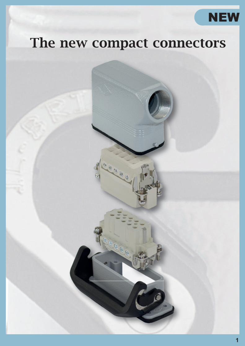
The new compact connectors
NEW
2
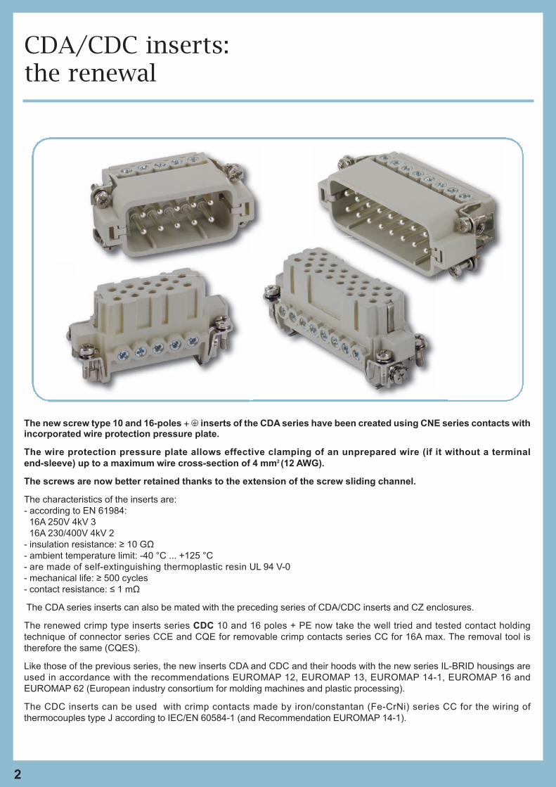
The new screw type 10 and 16-poles + m inserts of the CDA series have been created using CNE series contacts withincorporated wire protection pressure plate.
The wire protection pressure plate allows effective clamping of an unprepared wire (if it without a terminal
end-sleeve) up to a maximum wire cross-section of 4 mm2 (12 AWG).
The screws are now better retained thanks to the extension of the screw sliding channel.
The characteristics of the inserts are:
- according to EN 61984:
16A 250V 4kV 3
16A 230/400V 4kV 2
- insulation resistance: ≥ 10 GΩ
- ambient temperature limit: -40 °C ... +125 °C
- are made of self-extinguishing thermoplastic resin UL 94 V-0
- mechanical life: ≥ 500 cycles
- contact resistance: ≤ 1 mΩ
The CDA series inserts can also be mated with the preceding series of CDA/CDC inserts and CZ enclosures.
The renewed crimp type inserts series CDC 10 and 16 poles + PE now take the well tried and tested contact holding
technique of connector series CCE and CQE for removable crimp contacts series CC for 16A max. The removal tool is
therefore the same (CQES).
Like those of the previous series, the new inserts CDA and CDC and their hoods with the new series IL-BRID housings are
used in accordance with the recommendations EUROMAP 12, EUROMAP 13, EUROMAP 14-1, EUROMAP 16 and
EUROMAP 62 (European industry consortium for molding machines and plastic processing).
The CDC inserts can be used with crimp contacts made by iron/constantan (Fe-CrNi) series CC for the wiring of
thermocouples type J according to IEC/EN 60584-1 (and Recommendation EUROMAP 14-1).
CDA/CDC inserts:the renewal
3
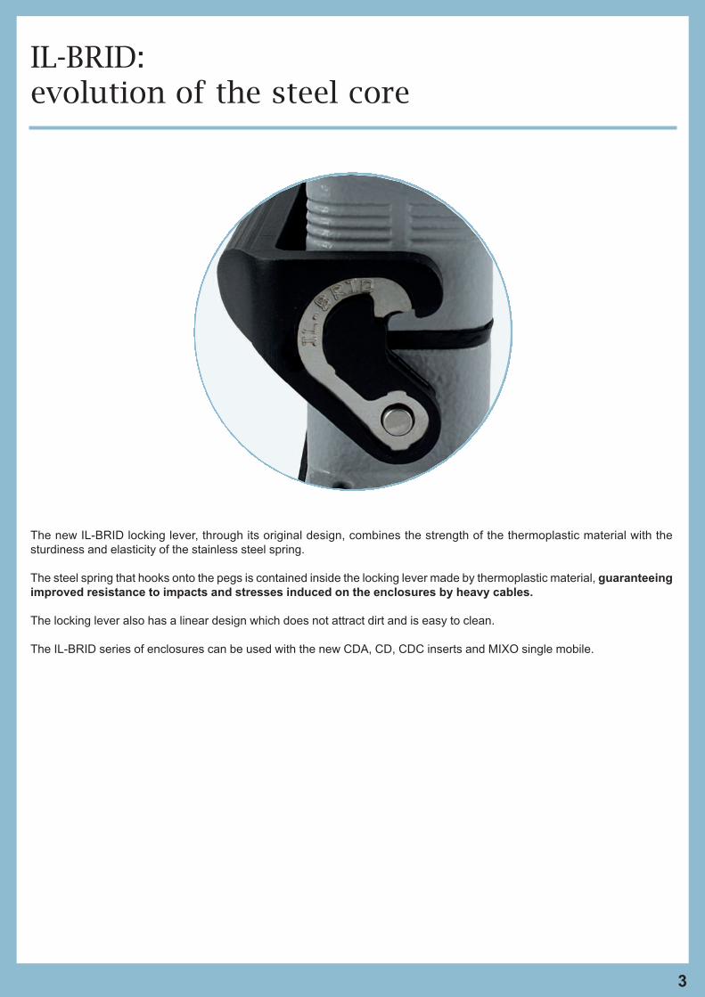
The new IL-BRID locking lever, through its original design, combines the strength of the thermoplastic material with the
sturdiness and elasticity of the stainless steel spring.
The steel spring that hooks onto the pegs is contained inside the locking lever made by thermoplastic material, guaranteeing
improved resistance to impacts and stresses induced on the enclosures by heavy cables.
The locking lever also has a linear design which does not attract dirt and is easy to clean.
The IL-BRID series of enclosures can be used with the new CDA, CD, CDC inserts and MIXO single mobile.
IL-BRID: evolution of the steel core
4
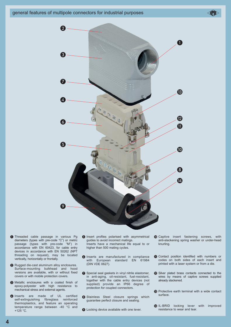
general features of multipole connectors for industrial purposes i
� Threaded cable passage in various Pgdiameters (types with pre-code “C”) or metric
passage (types with pre-code “M”) in
accordance with EN 60423, for cable entry
devices in accordance with EN 50262 (NPT
threading on request), may be located
vertically, horizontally or frontally.
� Rugged die-cast aluminum alloy enclosures.Surface-mounting bulkhead and hood
versions are available, with or without fixed
covers or with mobile protection covers.
� Metallic enclosures with a coated finish ofepoxy-polyester with high resistance to
mechanical stress and external agents.
� Inserts are made of UL certifiedself-extinguishing fibreglass reinforced
thermoplastics, and feature an operating
temperature range between -40 °C and
+125 °C.
� Insert profiles polarised with asymmetricalguides to avoid incorrect matings.
Inserts have a mechanical life equal to or
higher than 500 mating cycles.
� Inserts are manufactured in compliancewith European standard EN 61984
(DIN VDE 0627).
� Special seal gaskets in vinyl nitrile elastomer,in anti-aging, oil-resistant, fuel-resistant,
together with the cable entry devices (not
supplied) provide an IP66 degree of
protection for coupled connectors.
Stainless Steel closure springs whichguarantee perfect closure and sealing.
Locking device available with one lever.
� Captive insert fastening screws, withanti-slackening spring washer or under-head
knurling.
� Contact position identified with numbers orcodes on both sides of each insert and
printed with a laser system or from a die.
Silver plated brass contacts connected to thewires by means of captive screws supplied
already slackened.
� Protective earth terminal with a wide contactsurface.
� IL-BRID locking lever with improvedresistance to wear and tear.
�
�
�
�
�
�
�
�
�
�
�
5
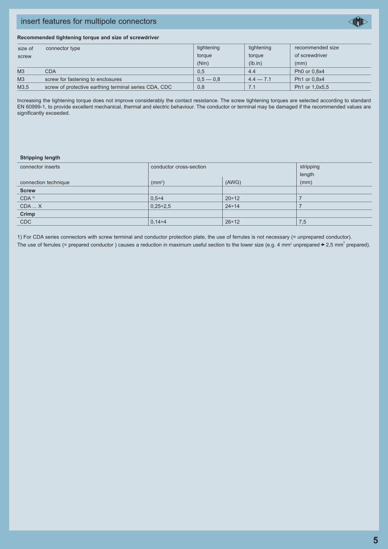
insert features for multipole connectors
Recommended tightening torque and size of screwdriver
M3 CDA 0,5 4.4 Ph0 or 0,8x4
M3 screw for fastening to enclosures 0,5 — 0,8 4.4 — 7.1 Ph1 or 0,8x4
M3,5 screw of protective earthing terminal series CDA, CDC 0,8 7.1 Ph1 or 1,0x5,5
Increasing the tightening torque does not improve considerably the contact resistance. The screw tightening torques are selected according to standard
EN 60999-1, to provide excellent mechanical, thermal and electric behaviour. The conductor or terminal may be damaged if the recommended values are
significantly exceeded.
size of
screw
connector type tightening
torque
(Nm)
tightening
torque
(Ib.in)
recommended size
of screwdriver
(mm)
Stripping length
Screw
CDA 1) 0,5÷4 20÷12 7
CDA ... X 0,25÷2,5 24÷14 7
Crimp
CDC 0,14÷4 26÷12 7,5
1) For CDA series connectors with screw terminal and conductor protection plate, the use of ferrules is not necessary (= unprepared conductor).
The use of ferrules (= prepared conductor ) causes a reduction in maximum useful section to the lower size (e.g. 4 mm2 unprepared 2,5 mm2
prepared).ò
connector inserts
connection technique
conductor cross-section
(mm2) (AWG)
stripping
length
(mm)
i
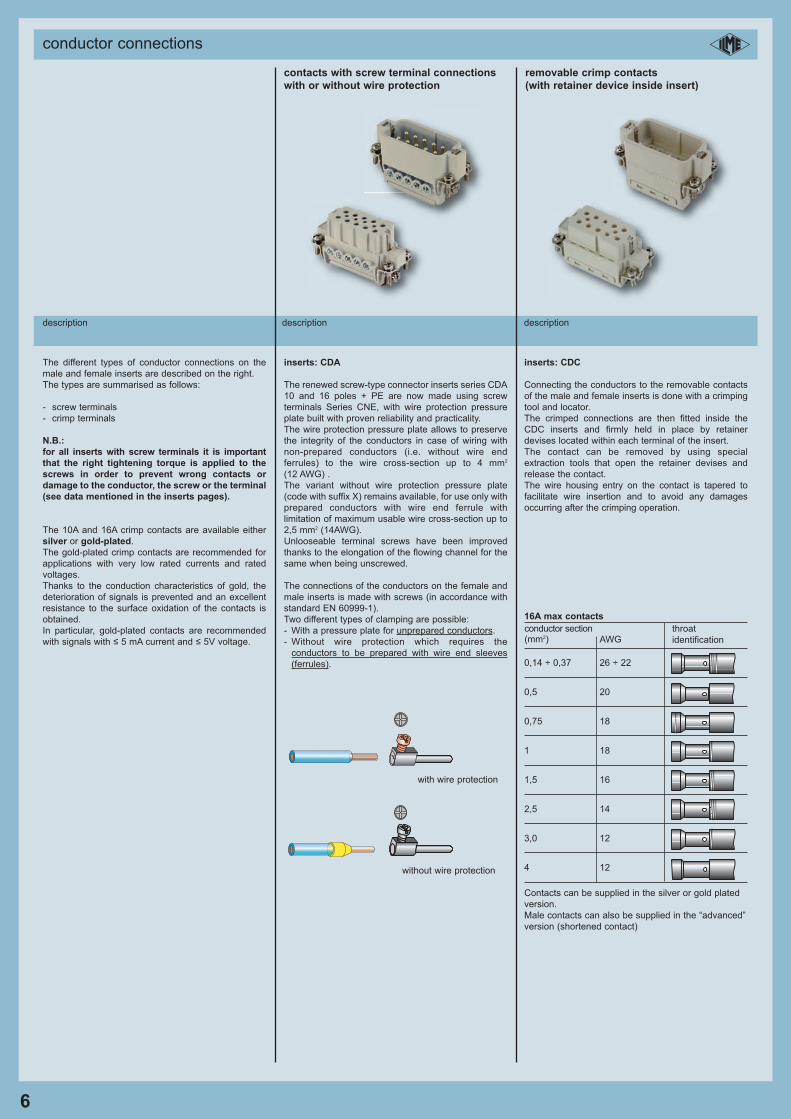
conductor connections
6
description description description
contacts with screw terminal connections removable crimp contacts
with or without wire protection (with retainer device inside insert)
The different types of conductor connections on the
male and female inserts are described on the right.
The types are summarised as follows:
- screw terminals
- crimp terminals
N.B.:
for all inserts with screw terminals it is important
that the right tightening torque is applied to the
screws in order to prevent wrong contacts or
damage to the conductor, the screw or the terminal
(see data mentioned in the inserts pages).
The 10A and 16A crimp contacts are available either
silver or gold-plated.
The gold-plated crimp contacts are recommended for
applications with very low rated currents and rated
voltages.
Thanks to the conduction characteristics of gold, the
deterioration of signals is prevented and an excellent
resistance to the surface oxidation of the contacts is
obtained.
In particular, gold-plated contacts are recommended
with signals with ≤ 5 mA current and ≤ 5V voltage.
inserts: CDA
The renewed screw-type connector inserts series CDA
10 and 16 poles + PE are now made using screw
terminals Series CNE, with wire protection pressure
plate built with proven reliability and practicality.
The wire protection pressure plate allows to preserve
the integrity of the conductors in case of wiring with
non-prepared conductors (i.e. without wire end
ferrules) to the wire cross-section up to 4 mm2
(12 AWG) .
The variant without wire protection pressure plate
(code with suffix X) remains available, for use only with
prepared conductors with wire end ferrule with
limitation of maximum usable wire cross-section up to
2,5 mm2 (14AWG).
Unlooseable terminal screws have been improved
thanks to the elongation of the flowing channel for the
same when being unscrewed.
The connections of the conductors on the female and
male inserts is made with screws (in accordance with
standard EN 60999-1).
Two different types of clamping are possible:
- With a pressure plate for unprepared conductors.
- Without wire protection which requires the
conductors to be prepared with wire end sleeves
(ferrules).
with wire protection
without wire protection
inserts: CDC
Connecting the conductors to the removable contacts
of the male and female inserts is done with a crimping
tool and locator.
The crimped connections are then fitted inside the
CDC inserts and firmly held in place by retainer
devises located within each terminal of the insert.
The contact can be removed by using special
extraction tools that open the retainer devises and
release the contact.
The wire housing entry on the contact is tapered to
facilitate wire insertion and to avoid any damages
occurring after the crimping operation.
16A max contacts
0,14 ÷ 0,37 26 ÷ 22
0,5 20
0,75 18
1 18
1,5 16
2,5 14
3,0 12
4 12
Contacts can be supplied in the silver or gold plated
version.
Male contacts can also be supplied in the “advanced”
version (shortened contact)
conductor section(mm2) AWG
throat
identification
i
enclosure versions and applications - enclosures and inserts combinations
7
description
The enclosures size “49.16” and “66.16” can be
used with the following inserts:
- Series CD and CDD (CDM/F 15 - 15P+PE for
size “49.16”, CDM/F 25 and CDDM/F 38 for
size “66.16”, respectively 25P+PE and
38P+PE) available with the crimp connection
technology of removable contacts series CD,
for current carrying capacity up to 10A.
- Series CDC available for crimp contacts with a
higher current rating up to 16A (CDCM/F 10,
CDCM/F 16).
- Series CDA available with screw-type terminals:
CDAM/F 10 and CDAM/F 16 (and their
variants).
- MIXO single module for inserts from 5A to 70A,
RJ45, USB, D-SUB and pneumatic.
IP66 and IP69 protection ratings.
characteristics of materials used:
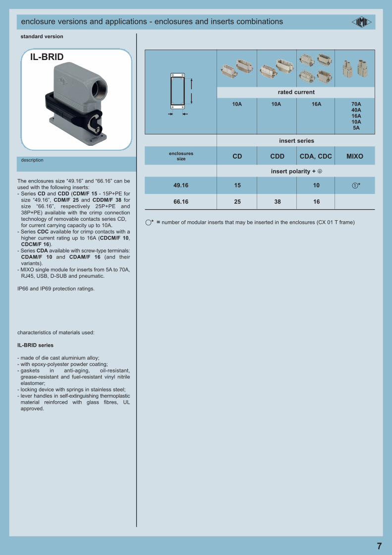
IL-BRID series
- made of die cast aluminium alloy;
- with epoxy-polyester powder coating;
- gaskets in anti-aging, oil-resistant,
grease-resistant and fuel-resistant vinyl nitrile
elastomer;
- locking device with springs in stainless steel;
- lever handles in self-extinguishing thermoplastic
material reinforced with glass fibres, UL
approved.
IL-BRID
standard version
i
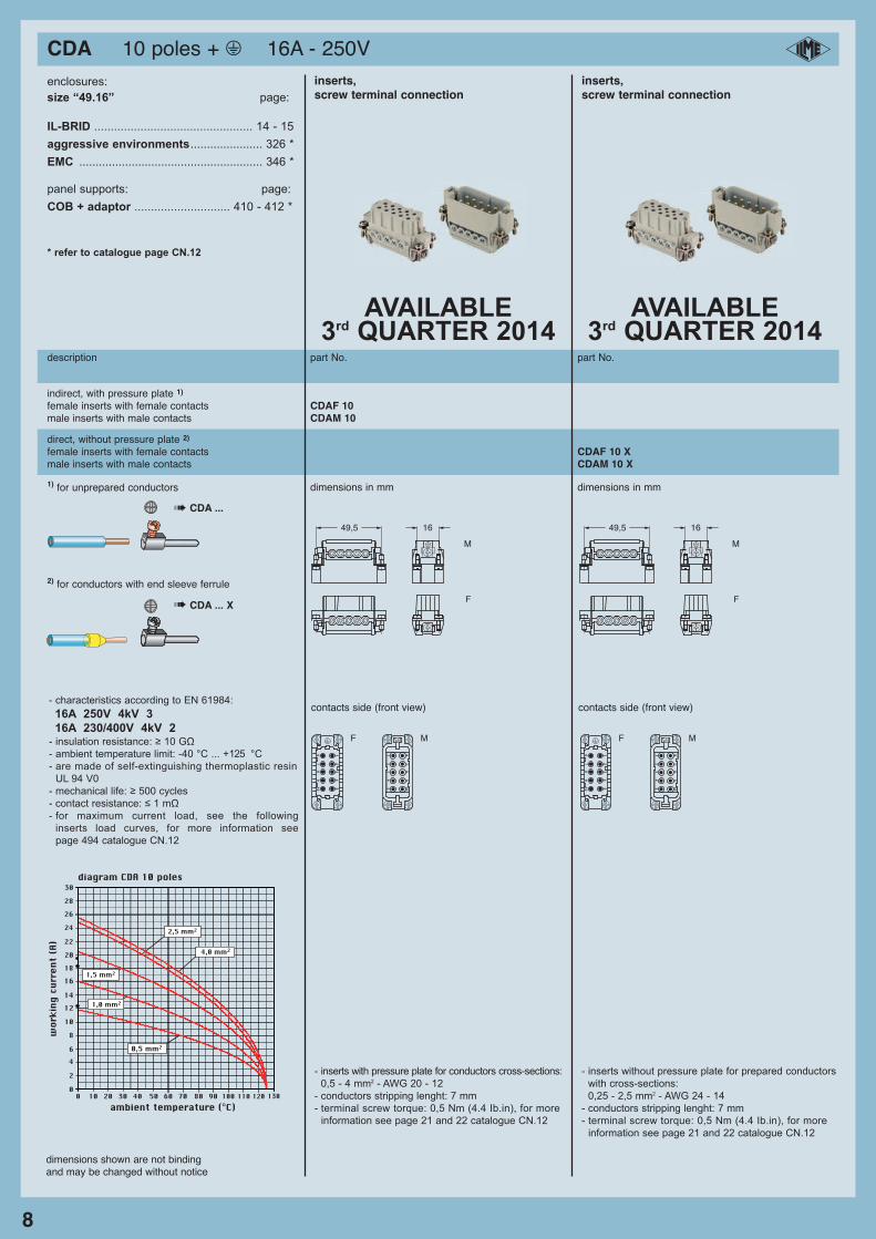
10A 10A 16A 70A40A16A10A5A
49.16 15 10 �*
66.16 25 38 16
CD CDD CDA, CDC MIXOenclosures
size
rated current
insert series
insert polarity + m
�* = number of modular inserts that may be inserted in the enclosures (CX 01 T frame)
CDA 10 poles + m 16A - 250V
8
dimensions shown are not bindingand may be changed without notice
enclosures:
size “49.16” page:
IL-BRID ................................................ 14 - 15
aggressive environments...................... 326 *
EMC ........................................................ 346 *
panel supports: page:
COB + adaptor ............................. 410 - 412 *
* refer to catalogue page CN.12
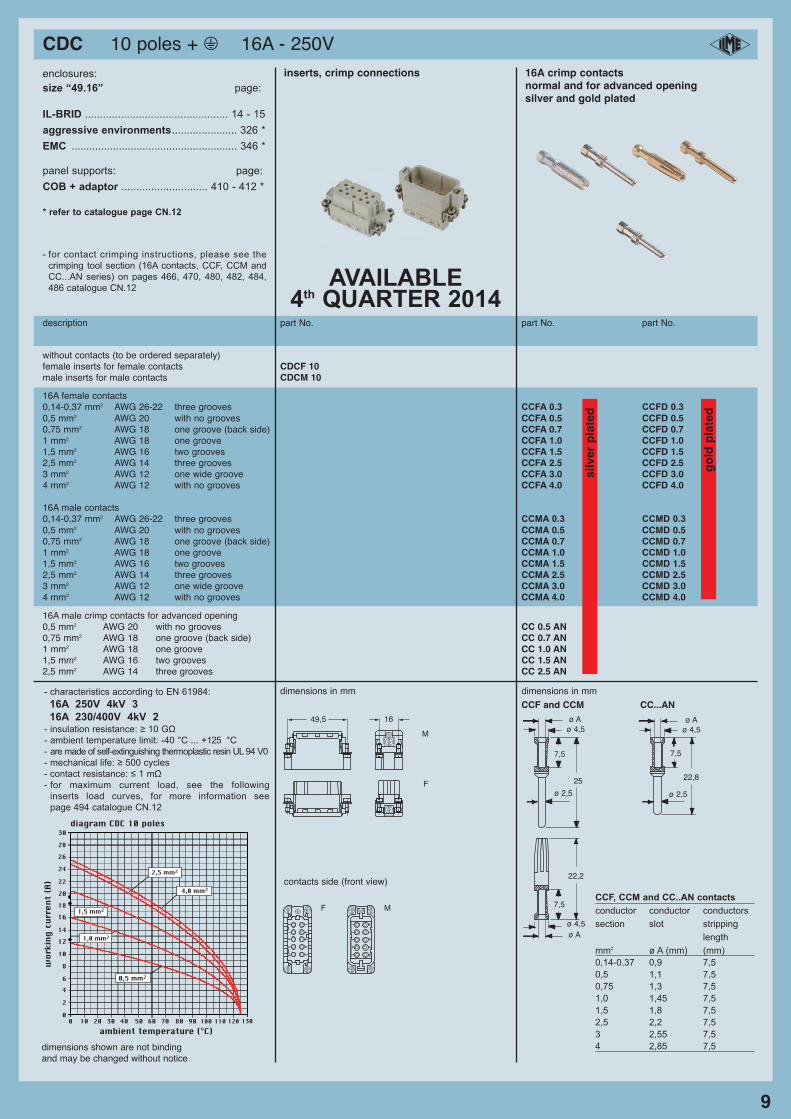
description part No. part No.
inserts, inserts, screw terminal connection screw terminal connection
direct, without pressure plate 2)
female inserts with female contacts CDAF 10 Xmale inserts with male contacts CDAM 10 X
indirect, with pressure plate 1)
female inserts with female contacts CDAF 10male inserts with male contacts CDAM 10
dimensions in mm dimensions in mm
contacts side (front view) contacts side (front view)
1) for unprepared conductors
2) for conductors with end sleeve ferrule
➠ CDA ...
➠ CDA ... X
- characteristics according to EN 61984:
16A 250V 4kV 3
16A 230/400V 4kV 2- insulation resistance: ≥ 10 GΩ
- ambient temperature limit: -40 °C ... +125 °C
- are made of self-extinguishing thermoplastic resin
UL 94 V0
- mechanical life: ≥ 500 cycles
- contact resistance: ≤ 1 mΩ
- for maximum current load, see the following
inserts load curves, for more information see
page 494 catalogue CN.12
10 20 30 40 50 60 70 80 90 100 1100 120 1300
2
46
10
8
1214
16
30
20
2826
24
22
18
2,5 mm2
1,5 mm2
1,0 mm2
0,5 mm2
4,0 mm2
ambient temperature (°C)
wor
king
cur
rent
(A)
diagram CDA 10 poles
i
12
34
5
67
89
10
12
34
5
67
89
10
49,5
M
F
16
F M
- inserts with pressure plate for conductors cross-sections:
0,5 - 4 mm2 - AWG 20 - 12
- conductors stripping lenght: 7 mm
- terminal screw torque: 0,5 Nm (4.4 Ib.in), for more
information see page 21 and 22 catalogue CN.12
- inserts without pressure plate for prepared conductors
with cross-sections:
0,25 - 2,5 mm2 - AWG 24 - 14
- conductors stripping lenght: 7 mm
- terminal screw torque: 0,5 Nm (4.4 Ib.in), for more
information see page 21 and 22 catalogue CN.12
AVAILABLE 3rd QUARTER 2014
AVAILABLE 3rd QUARTER 2014
12
34
5
67
89
10
12
34
5
67
89
10
49,5
M
F
16
F M
CDC 10 poles + m 16A - 250V
9
enclosures:
size “49.16” page:
IL-BRID ................................................ 14 - 15
aggressive environments...................... 326 *
EMC ........................................................ 346 *
panel supports: page:
COB + adaptor ............................. 410 - 412 *
* refer to catalogue page CN.12
description part No. part No. part No.
inserts, crimp connections 16A crimp contactsnormal and for advanced openingsilver and gold plated
without contacts (to be ordered separately)female inserts for female contacts CDCF 10male inserts for male contacts CDCM 10
contacts side (front view)
16A female contacts0,14-0,37 mm2 AWG 26-22 three grooves CCFA 0.3 CCFD 0.3
0,5 mm2 AWG 20 with no grooves CCFA 0.5 CCFD 0.50,75 mm2 AWG 18 one groove (back side) CCFA 0.7 CCFD 0.71 mm2 AWG 18 one groove CCFA 1.0 CCFD 1.01,5 mm2 AWG 16 two grooves CCFA 1.5 CCFD 1.52,5 mm2 AWG 14 three grooves CCFA 2.5 CCFD 2.53 mm2 AWG 12 one wide groove CCFA 3.0 CCFD 3.04 mm2 AWG 12 with no grooves CCFA 4.0 CCFD 4.0
16A male contacts 0,14-0,37 mm2 AWG 26-22 three grooves CCMA 0.3 CCMD 0.3
0,5 mm2 AWG 20 with no grooves CCMA 0.5 CCMD 0.50,75 mm2 AWG 18 one groove (back side) CCMA 0.7 CCMD 0.71 mm2 AWG 18 one groove CCMA 1.0 CCMD 1.01,5 mm2 AWG 16 two grooves CCMA 1.5 CCMD 1.52,5 mm2 AWG 14 three grooves CCMA 2.5 CCMD 2.53 mm2 AWG 12 one wide groove CCMA 3.0 CCMD 3.04 mm2 AWG 12 with no grooves CCMA 4.0 CCMD 4.0
silv
er p
late
d
go
ld p
late
d
16A male crimp contacts for advanced opening0,5 mm2 AWG 20 with no grooves CC 0.5 AN0,75 mm2 AWG 18 one groove (back side) CC 0.7 AN1 mm2 AWG 18 one groove CC 1.0 AN1,5 mm2 AWG 16 two grooves CC 1.5 AN2,5 mm2 AWG 14 three grooves CC 2.5 AN
dimensions in mm dimensions in mm
CCF and CCM CC...AN
- for contact crimping instructions, please see the
crimping tool section (16A contacts, CCF, CCM and
CC...AN series) on pages 466, 470, 480, 482, 484,
486 catalogue CN.12
- characteristics according to EN 61984:
16A 250V 4kV 3
16A 230/400V 4kV 2- insulation resistance: ≥ 10 GΩ
- ambient temperature limit: -40 °C ... +125 °C
- are made of self-extinguishing thermoplastic resin UL 94 V0
- mechanical life: ≥ 500 cycles
- contact resistance: ≤ 1 mΩ
- for maximum current load, see the following
inserts load curves, for more information see
page 494 catalogue CN.12
10 20 30 40 50 60 70 80 90 100 1100 120 1300
2
46
10
8
1214
16
30
20
2826
24
22
18
2,5 mm2
1,5 mm2
1,0 mm2
0,5 mm2
4,0 mm2
ambient temperature (°C)
wor
king
cur
rent
(A)
diagram CDC 10 poles
i
12
34
5
67
89
10
12
34
5
67
89
10
49,5
M
F
16
F M
22,2
25
7,5
7,5
ø 2,5
ø Aø 4,5
ø Aø 4,5
22,8
7,5
ø 2,5
ø Aø 4,5
CCF, CCM and CC..AN contacts
conductor conductor conductors
section slot stripping
length
mm2 ø A (mm) (mm)
0,14-0,37 0,9 7,5
0,5 1,1 7,5
0,75 1,3 7,5
1,0 1,45 7,5
1,5 1,8 7,5
2,5 2,2 7,5
3 2,55 7,5
4 2,85 7,5dimensions shown are not bindingand may be changed without notice
AVAILABLE 4th QUARTER 2014
CDA 16 poles + m 16A - 250V
10
dimensions shown are not bindingand may be changed without notice
enclosures:
size “66.16” page:
IL-BRID ................................................ 16 - 18
aggressive environments...................... 327 *
EMC ........................................................ 347 *
panel supports: page:
COB + adaptor ............................. 410 - 412 *
* refer to catalogue page CN.12
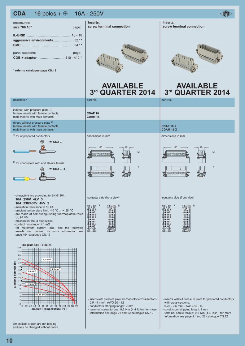
description part No. part No.
inserts, inserts, screw terminal connection screw terminal connection
direct, without pressure plate 2)
female inserts with female contacts CDAF 16 Xmale inserts with male contacts CDAM 16 X
indirect, with pressure plate 1)
female inserts with female contacts CDAF 16male inserts with male contacts CDAM 16
contacts side (front view) contacts side (front view)
2,5 mm2
1,5 mm2
1,0 mm2
0,5 m-m2
4,0 mm2
0
2
46
10
8
1214
16
30
20
2826
24
22
18
10 20 30 40 50 60 70 80 90 100 1100 120 130ambient temperature (°C)
wor
king
cur
rent
(A)
diagram CDA 16 poles
- characteristics according to EN 61984:
16A 250V 4kV 3
16A 230/400V 4kV 2- insulation resistance: ≥ 10 GΩ
- ambient temperature limit: -40 °C ... +125 °C
- are made of self-extinguishing thermoplastic resin
UL 94 V0
- mechanical life: ≥ 500 cycles
- contact resistance: ≤ 1 mΩ
- for maximum current load, see the following
inserts load curves, for more information see
page 494 catalogue CN.12
i
12
34
56
78
910
11
12
13
14
15
16
12
34
56
78
910
11
12
13
14
15
16
66
M
F
16
F M
- inserts with pressure plate for conductors cross-sections:
0,5 - 4 mm2 - AWG 20 - 12
- conductors stripping lenght: 7 mm
- terminal screw torque: 0,5 Nm (4.4 Ib.in), for more
information see page 21 and 22 catalogue CN.12
- inserts without pressure plate for prepared conductors
with cross-sections:
0,25 - 2,5 mm2 - AWG 24 - 14
- conductors stripping lenght: 7 mm
- terminal screw torque: 0,5 Nm (4.4 Ib.in), for more
information see page 21 and 22 catalogue CN.12
dimensions in mm dimensions in mm1) for unprepared conductors
2) for conductors with end sleeve ferrule
➠ CDA ...
➠ CDA ... X
AVAILABLE 3rd QUARTER 2014
AVAILABLE 3rd QUARTER 2014
12
34
56
78
910
11
12
13
14
15
16
12
34
56
78
910
11
12
13
14
15
16
66
M
F
16
F M
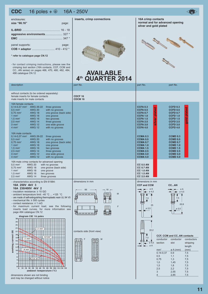
CDC 16 poles + m 16A - 250V
11
enclosures:
size “66.16” page:
IL-BRID ................................................ 16 - 18
aggressive environments...................... 327 *
EMC ........................................................ 347 *
panel supports: page:
COB + adaptor ............................. 410 - 412 *
* refer to catalogue page CN.12
description part No. part No. part No.
without contacts (to be ordered separately)female inserts for female contacts CDCF 16male inserts for male contacts CDCM 16
inserts, crimp connections 16A crimp contactsnormal and for advanced openingsilver and gold plated
contacts side (front view)
16A female contacts0,14-0,37 mm2 AWG 26-22 three grooves CCFA 0.3 CCFD 0.3
0,5 mm2 AWG 20 with no grooves CCFA 0.5 CCFD 0.50,75 mm2 AWG 18 one groove (back side) CCFA 0.7 CCFD 0.71 mm2 AWG 18 one groove CCFA 1.0 CCFD 1.01,5 mm2 AWG 16 two grooves CCFA 1.5 CCFD 1.52,5 mm2 AWG 14 three grooves CCFA 2.5 CCFD 2.53 mm2 AWG 12 one wide groove CCFA 3.0 CCFD 3.04 mm2 AWG 12 with no grooves CCFA 4.0 CCFD 4.0
16A male contacts 0,14-0,37 mm2 AWG 26-22 three grooves CCMA 0.3 CCMD 0.3
0,5 mm2 AWG 20 with no grooves CCMA 0.5 CCMD 0.50,75 mm2 AWG 18 one groove (back side) CCMA 0.7 CCMD 0.71 mm2 AWG 18 one groove CCMA 1.0 CCMD 1.01,5 mm2 AWG 16 two grooves CCMA 1.5 CCMD 1.52,5 mm2 AWG 14 three grooves CCMA 2.5 CCMD 2.53 mm2 AWG 12 one wide groove CCMA 3.0 CCMD 3.04 mm2 AWG 12 with no grooves CCMA 4.0 CCMD 4.0
silv
er p
late
d
go
ld p
late
d
16A male crimp contacts for advanced opening0,5 mm2 AWG 20 with no grooves CC 0.5 AN0,75 mm2 AWG 18 one groove (back side) CC 0.7 AN1 mm2 AWG 18 one groove CC 1.0 AN1,5 mm2 AWG 16 two grooves CC 1.5 AN2,5 mm2 AWG 14 three grooves CC 2.5 AN
dimensions in mm dimensions in mm
CCF and CCM CC...AN
- for contact crimping instructions, please see the
crimping tool section (16A contacts, CCF, CCM and
CC...AN series) on pages 466, 470, 480, 482, 484,
486 catalogue CN.12
- characteristics according to EN 61984:
16A 250V 4kV 3
16A 230/400V 4kV 2- insulation resistance: ≥ 10 GΩ
- ambient temperature limit: -40 °C ... +125 °C
- are made of self-extinguishing thermoplastic resin UL 94 V0
- mechanical life: ≥ 500 cycles
- contact resistance: ≤ 1 mΩ
- for maximum current load, see the following
inserts load curves, for more information see
page 494 catalogue CN.12
2,5 mm2
1,5 mm2
1,0 mm2
0,5 m-m2
4,0 mm2
0
2
46
10
8
1214
16
30
20
2826
24
22
18
10 20 30 40 50 60 70 80 90 100 1100 120 130ambient temperature (°C)
wor
king
cur
rent
(A)
diagram CDC 16 poles
i
12
34
56
78
910
11
12
13
14
15
16
12
34
56
78
910
11
12
13
14
15
16
66
M
F
16
F M
22,2
25
7,5
7,5
ø 2,5
ø Aø 4,5
ø Aø 4,5
22,8
7,5
ø 2,5
ø Aø 4,5
CCF, CCM and CC..AN contacts
conductor conductor conductors
section slot stripping
length
mm2 ø A (mm) (mm)
0,14-0,37 0,9 7,5
0,5 1,1 7,5
0,75 1,3 7,5
1,0 1,45 7,5
1,5 1,8 7,5
2,5 2,2 7,5
3 2,55 7,5
4 2,85 7,5dimensions shown are not bindingand may be changed without notice
AVAILABLE 4th QUARTER 2014
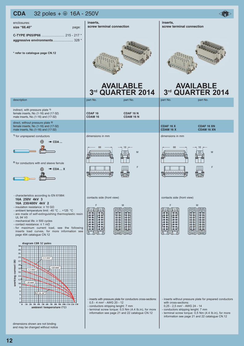
CDA 32 poles + m 16A - 250V
12
dimensions shown are not bindingand may be changed without notice
enclosures:
size “66.40” page:
C-TYPE IP65/IP66 ......................... 215 - 217 *
aggressive environments...................... 328 *
* refer to catalogue page CN.12
description part No. part No. part No. part No.
inserts, inserts, screw terminal connection screw terminal connection
direct, without pressure plate 2)
female inserts, No. (1-16) and (17-32) CDAF 16 X CDAF 16 XNmale inserts, No. (1-16) and (17-32) CDAM 16 X CDAM 16 XN
indirect, with pressure plate 1)
female inserts, No. (1-16) and (17-32) CDAF 16 CDAF 16 Nmale inserts, No. (1-16) and (17-32) CDAM 16 CDAM 16 N
contacts side (front view) contacts side (front view)
- inserts with pressure plate for conductors cross-sections:
0,5 - 4 mm2 - AWG 20 - 12
- conductors stripping lenght: 7 mm
- terminal screw torque: 0,5 Nm (4.4 Ib.in), for more
information see page 21 and 22 catalogue CN.12
- inserts without pressure plate for prepared conductors
with cross-sections:
0,25 - 2,5 mm2 - AWG 24 - 14
- conductors stripping lenght: 7 mm
- terminal screw torque: 0,5 Nm (4.4 Ib.in), for more
information see page 21 and 22 catalogue CN.12
1725
26
27
28
29
30
31
32
12
34
56
78
910
11
12
13
14
15
16
12
34
56
78
910
11
12
13
14
15
16
18
19
20
21
22
23
24
17
18
19
20
21
22
23
24
25
26
27
28
29
30
31
32
F M
- characteristics according to EN 61984:
16A 250V 4kV 3
16A 230/400V 4kV 2- insulation resistance: ≥ 10 GΩ
- ambient temperature limit: -40 °C ... +125 °C
- are made of self-extinguishing thermoplastic resin
UL 94 V0
- mechanical life: ≥ 500 cycles
- contact resistance: ≤ 1 mΩ
- for maximum current load, see the following
inserts load curves, for more information see
page 494 catalogue CN.12
2,5 mm2
1,5 mm2
1,0 mm2
0,5 m-m2
4,0 mm2
0
2
46
10
8
1214
16
30
20
2826
24
22
18
10 20 30 40 50 60 70 80 90 100 1100 120 130ambient temperature (°C)
wor
king
cur
rent
(A)
diagram CDA 32 poles
i
dimensions in mm dimensions in mm1) for unprepared conductors
2) for conductors with end sleeve ferrule
➠ CDA ...
➠ CDA ... X
AVAILABLE 3rd QUARTER 2014
AVAILABLE 3rd QUARTER 2014
66
M
F
16
66
M
F
16
1725
26
27
28
29
30
31
32
12
34
56
78
910
11
12
13
14
15
16
12
34
56
78
910
11
12
13
14
15
16
18
19
20
21
22
23
24
17
18
19
20
21
22
23
24
25
26
27
28
29
30
31
32
F M
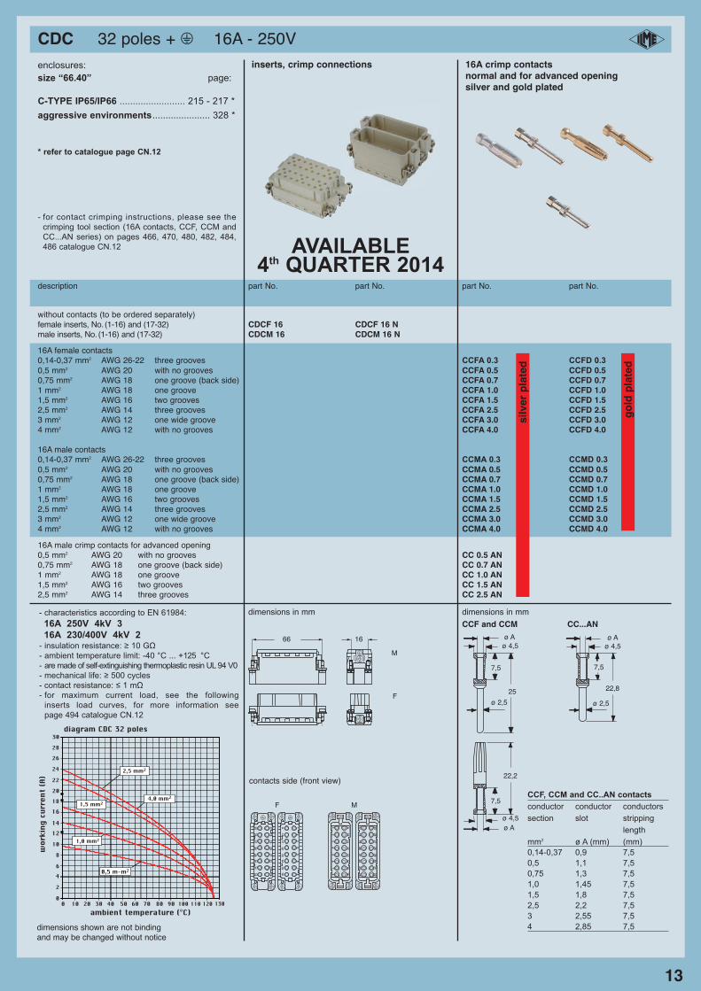
CDC 32 poles + m 16A - 250V
13
enclosures:
size “66.40” page:
C-TYPE IP65/IP66 ......................... 215 - 217 *
aggressive environments...................... 328 *
* refer to catalogue page CN.12
description part No. part No. part No. part No.
without contacts (to be ordered separately)female inserts, No. (1-16) and (17-32) CDCF 16 CDCF 16 Nmale inserts, No. (1-16) and (17-32) CDCM 16 CDCM 16 N
12
34
56
78
910
11
12
13
14
15
16
17
25
26
27
28
29
30
31
32
18
19
20
21
22
23
24
12
34
56
78
910
11
12
13
14
15
16
17
18
19
20
21
22
23
24
25
26
27
28
29
30
31
32
F M
inserts, crimp connections 16A crimp contactsnormal and for advanced openingsilver and gold plated
contacts side (front view)22,2
25
7,5
7,5
ø 2,5
ø Aø 4,5
ø Aø 4,5
22,8
7,5
ø 2,5
ø Aø 4,5
16A female contacts0,14-0,37 mm2 AWG 26-22 three grooves CCFA 0.3 CCFD 0.3
0,5 mm2 AWG 20 with no grooves CCFA 0.5 CCFD 0.50,75 mm2 AWG 18 one groove (back side) CCFA 0.7 CCFD 0.71 mm2 AWG 18 one groove CCFA 1.0 CCFD 1.01,5 mm2 AWG 16 two grooves CCFA 1.5 CCFD 1.52,5 mm2 AWG 14 three grooves CCFA 2.5 CCFD 2.53 mm2 AWG 12 one wide groove CCFA 3.0 CCFD 3.04 mm2 AWG 12 with no grooves CCFA 4.0 CCFD 4.0
16A male contacts 0,14-0,37 mm2 AWG 26-22 three grooves CCMA 0.3 CCMD 0.3
0,5 mm2 AWG 20 with no grooves CCMA 0.5 CCMD 0.50,75 mm2 AWG 18 one groove (back side) CCMA 0.7 CCMD 0.71 mm2 AWG 18 one groove CCMA 1.0 CCMD 1.01,5 mm2 AWG 16 two grooves CCMA 1.5 CCMD 1.52,5 mm2 AWG 14 three grooves CCMA 2.5 CCMD 2.53 mm2 AWG 12 one wide groove CCMA 3.0 CCMD 3.04 mm2 AWG 12 with no grooves CCMA 4.0 CCMD 4.0
silv
er p
late
d
go
ld p
late
d
16A male crimp contacts for advanced opening0,5 mm2 AWG 20 with no grooves CC 0.5 AN0,75 mm2 AWG 18 one groove (back side) CC 0.7 AN1 mm2 AWG 18 one groove CC 1.0 AN1,5 mm2 AWG 16 two grooves CC 1.5 AN2,5 mm2 AWG 14 three grooves CC 2.5 AN
dimensions in mm dimensions in mm
CCF and CCM CC...AN
CCF, CCM and CC..AN contacts
conductor conductor conductors
section slot stripping
length
mm2 ø A (mm) (mm)
0,14-0,37 0,9 7,5
0,5 1,1 7,5
0,75 1,3 7,5
1,0 1,45 7,5
1,5 1,8 7,5
2,5 2,2 7,5
3 2,55 7,5
4 2,85 7,5dimensions shown are not bindingand may be changed without notice
- for contact crimping instructions, please see the
crimping tool section (16A contacts, CCF, CCM and
CC...AN series) on pages 466, 470, 480, 482, 484,
486 catalogue CN.12
- characteristics according to EN 61984:
16A 250V 4kV 3
16A 230/400V 4kV 2- insulation resistance: ≥ 10 GΩ
- ambient temperature limit: -40 °C ... +125 °C
- are made of self-extinguishing thermoplastic resin UL 94 V0
- mechanical life: ≥ 500 cycles
- contact resistance: ≤ 1 mΩ
- for maximum current load, see the following
inserts load curves, for more information see
page 494 catalogue CN.12
2,5 mm2
1,5 mm2
1,0 mm2
0,5 m-m2
4,0 mm2
0
2
46
10
8
1214
16
30
20
2826
24
22
18
10 20 30 40 50 60 70 80 90 100 1100 120 130ambient temperature (°C)
wor
king
cur
rent
(A)
diagram CDC 32 poles
i
66
M
F
16
AVAILABLE 4th QUARTER 2014
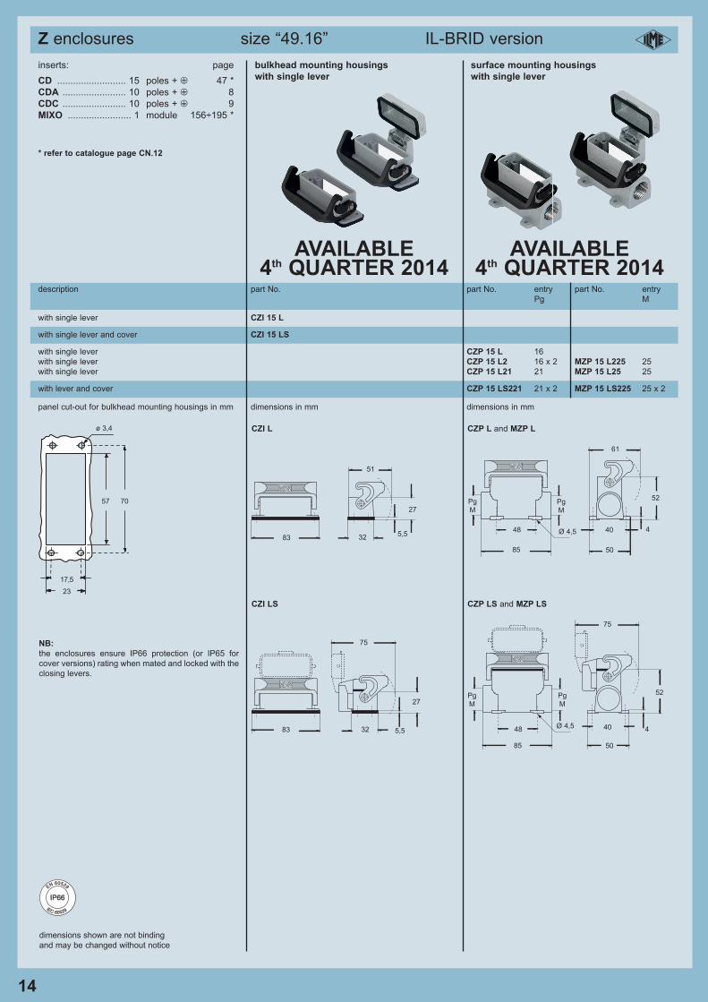
Z enclosures size “49.16” IL-BRID version
14
dimensions shown are not binding
and may be changed without notice
inserts: page
CD .......................... 15 poles + m 47 *
CDA ........................ 10 poles + m 8CDC ........................ 10 poles + m 9MIXO ........................ 1 module 156÷195 *
* refer to catalogue page CN.12
description part No. part No. entry part No. entry
Pg M
with single lever CZI 15 L
with single lever and cover CZI 15 LS
with lever and cover CZP 15 LS221 21 x 2 MZP 15 LS225 25 x 2
with single lever CZP 15 L 16
with single lever CZP 15 L2 16 x 2 MZP 15 L225 25
with single lever CZP 15 L21 21 MZP 15 L25 25
panel cut-out for bulkhead mounting housings in mm dimensions in mm dimensions in mm
CZI L CZP L and MZP L
CZI LS CZP LS and MZP LS
57 70
17,5
23
ø 3,4
NB:
the enclosures ensure IP66 protection (or IP65 for
cover versions) rating when mated and locked with the
closing levers.
IP66IP66
EN 60529
IEC 60529
i
83
75
32
27
75
48
85
Pg
M
Pg
M
40
50
4Ø 4,5
52
5,5
83
51
32
27
5,548
85
Pg
M
Pg
M
61
40
50
4
52
Ø 4,5
bulkhead mounting housings surface mounting housings
with single lever with single lever
AVAILABLE 4th QUARTER 2014
AVAILABLE 4th QUARTER 2014
15
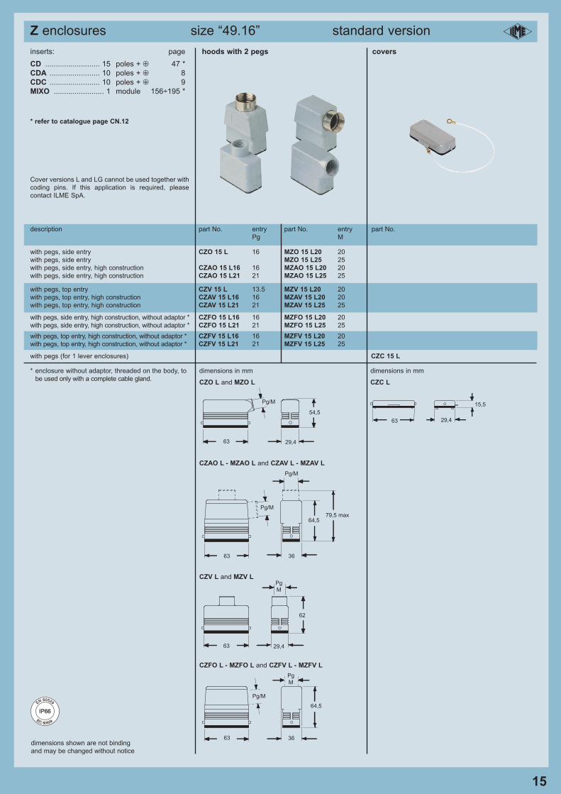
Z enclosures size “49.16” standard version
inserts: page
CD .......................... 15 poles + m 47 *
CDA ........................ 10 poles + m 8CDC ........................ 10 poles + m 9MIXO ........................ 1 module 156÷195 *
* refer to catalogue page CN.12
Cover versions L and LG cannot be used together with
coding pins. If this application is required, please
contact ILME SpA.
description part No. entry part No. entry part No.Pg M
hoods with 2 pegs covers
with pegs, side entry CZO 15 L 16 MZO 15 L20 20
with pegs, side entry MZO 15 L25 25
with pegs, side entry, high construction CZAO 15 L16 16 MZAO 15 L20 20
with pegs, side entry, high construction CZAO 15 L21 21 MZAO 15 L25 25
with pegs, top entry CZV 15 L 13.5 MZV 15 L20 20
with pegs, top entry, high construction CZAV 15 L16 16 MZAV 15 L20 20
with pegs, top entry, high construction CZAV 15 L21 21 MZAV 15 L25 25
with pegs, side entry, high construction, without adaptor * CZFO 15 L16 16 MZFO 15 L20 20
with pegs, side entry, high construction, without adaptor * CZFO 15 L21 21 MZFO 15 L25 25
with pegs, top entry, high construction, without adaptor * CZFV 15 L16 16 MZFV 15 L20 20
with pegs, top entry, high construction, without adaptor * CZFV 15 L21 21 MZFV 15 L25 25
with pegs (for 1 lever enclosures) CZC 15 L
dimensions in mm dimensions in mm
CZAO L - MZAO L and CZAV L - MZAV L
CZV L and MZV L
Pg/M
29,463
54,5
63
Pg
M
29,4
62
15,5
63 29,4
63
Pg
M
36
64,5
Pg/M
3663
64,5
CZFO L - MZFO L and CZFV L - MZFV L
Pg/M
79,5 max
Pg/M
dimensions shown are not binding
and may be changed without notice
* enclosure without adaptor, threaded on the body, to
be used only with a complete cable gland.
i
IP66IP66
EN 60529
IEC 60529
CZO L and MZO L CZC L
16
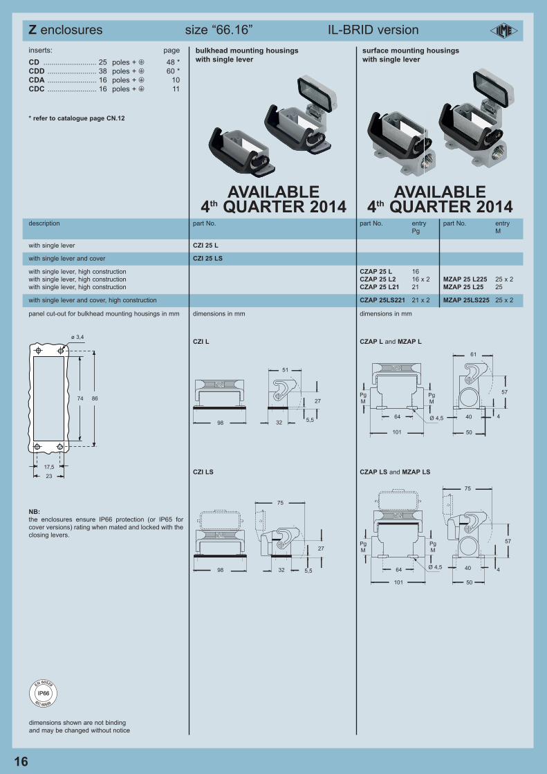
dimensions shown are not binding
and may be changed without notice
inserts: page
CD .......................... 25 poles + m 48 *
CDD ........................ 38 poles + m 60 *
CDA ........................ 16 poles + m 10
CDC ........................ 16 poles + m 11
* refer to catalogue page CN.12
description part No. part No. entry part No. entry
Pg M
with single lever CZI 25 L
with single lever and cover CZI 25 LS
with single lever and cover, high construction CZAP 25LS221 21 x 2 MZAP 25LS225 25 x 2
with single lever, high construction CZAP 25 L 16
with single lever, high construction CZAP 25 L2 16 x 2 MZAP 25 L225 25 x 2
with single lever, high construction CZAP 25 L21 21 MZAP 25 L25 25
panel cut-out for bulkhead mounting housings in mm dimensions in mm dimensions in mm
CZI L CZAP L and MZAP L
CZI LS CZAP LS and MZAP LS
74 86
17,5
23
ø 3,4
98
75
32
27
75
64
101
Pg
M
Pg
M
40
50
4Ø 4,5
57
5,5
NB:
the enclosures ensure IP66 protection (or IP65 for
cover versions) rating when mated and locked with the
closing levers.
Z enclosures size “66.16” IL-BRID version i
IP66IP66
EN 60529
IEC 60529
98
51
32
27
5,564
101
Pg
M
Pg
M
61
40
50
4
57
Ø 4,5
AVAILABLE 4th QUARTER 2014
AVAILABLE 4th QUARTER 2014
bulkhead mounting housings surface mounting housings
with single lever with single lever
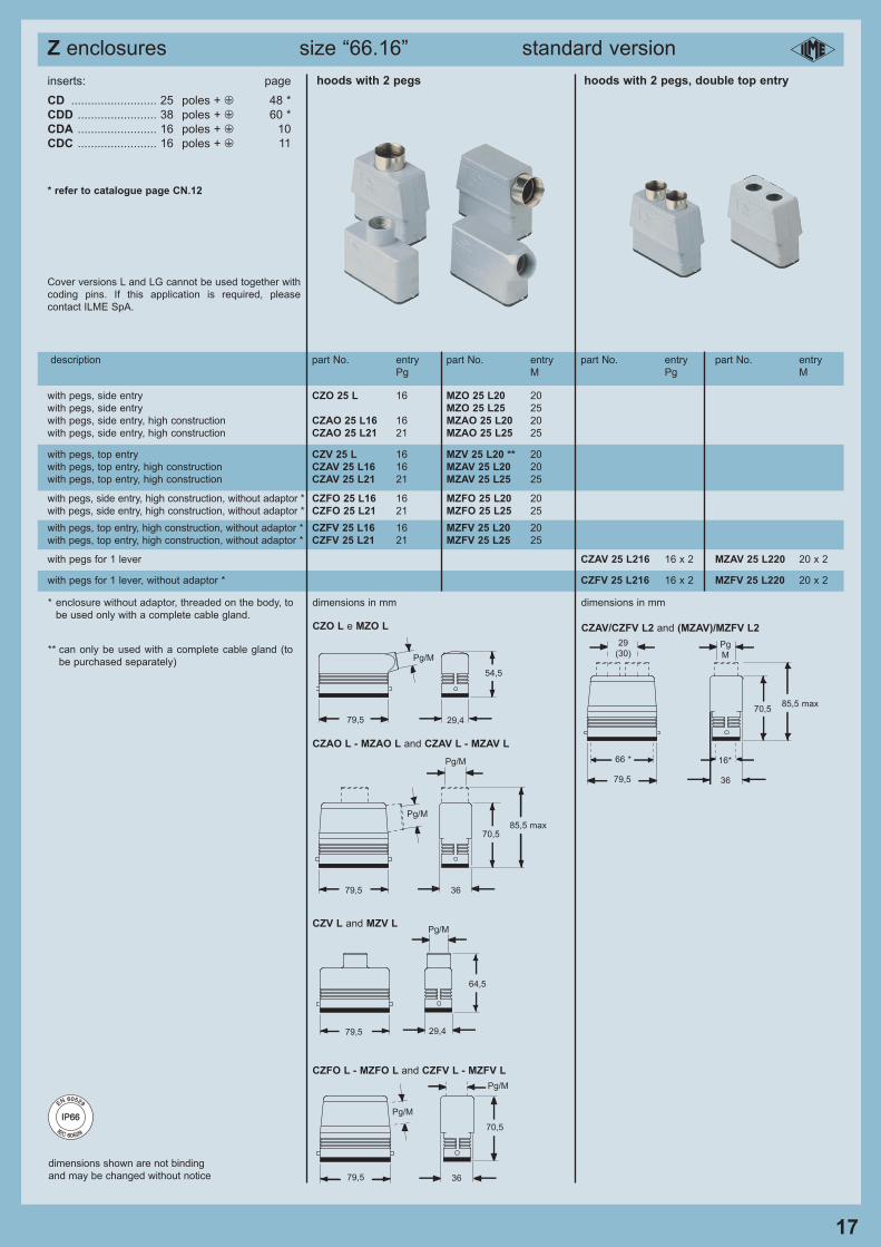
dimensions shown are not binding
and may be changed without notice
inserts: page
CD .......................... 25 poles + m 48 *
CDD ........................ 38 poles + m 60 *
CDA ........................ 16 poles + m 10
CDC ........................ 16 poles + m 11
* refer to catalogue page CN.12
Cover versions L and LG cannot be used together with
coding pins. If this application is required, please
contact ILME SpA.
description part No. entry part No. entry part No. entry part No. entry
Pg M Pg M
hoods with 2 pegs hoods with 2 pegs, double top entry
with pegs, side entry CZO 25 L 16 MZO 25 L20 20
with pegs, side entry MZO 25 L25 25
with pegs, side entry, high construction CZAO 25 L16 16 MZAO 25 L20 20
with pegs, side entry, high construction CZAO 25 L21 21 MZAO 25 L25 25
with pegs, top entry CZV 25 L 16 MZV 25 L20 ** 20
with pegs, top entry, high construction CZAV 25 L16 16 MZAV 25 L20 20
with pegs, top entry, high construction CZAV 25 L21 21 MZAV 25 L25 25
with pegs for 1 lever CZAV 25 L216 16 x 2 MZAV 25 L220 20 x 2
with pegs for 1 lever, without adaptor * CZFV 25 L216 16 x 2 MZFV 25 L220 20 x 2
dimensions in mm dimensions in mm
CZO L e MZO L CZAV/CZFV L2 and (MZAV)/MZFV L2
CZAO L - MZAO L and CZAV L - MZAV L
CZV L and MZV L
Pg/M
29,479,5
54,5
79,5
Pg/M
29,4
64,5
CZFO L - MZFO L and CZFV L - MZFV L
** can only be used with a complete cable gland (to
be purchased separately)
79,5
Pg/M
36
70,5
Pg/M
3679,5
70,5
Pg/M
85,5 max
Pg/M
with pegs, top entry, high construction, without adaptor * CZFV 25 L16 16 MZFV 25 L20 20
with pegs, top entry, high construction, without adaptor * CZFV 25 L21 21 MZFV 25 L25 25
with pegs, side entry, high construction, without adaptor * CZFO 25 L16 16 MZFO 25 L20 20
with pegs, side entry, high construction, without adaptor * CZFO 25 L21 21 MZFO 25 L25 25
* enclosure without adaptor, threaded on the body, to
be used only with a complete cable gland.
17
Pg
M
36
66 *
85,5 max70,5
29
(30)
79,5
16*
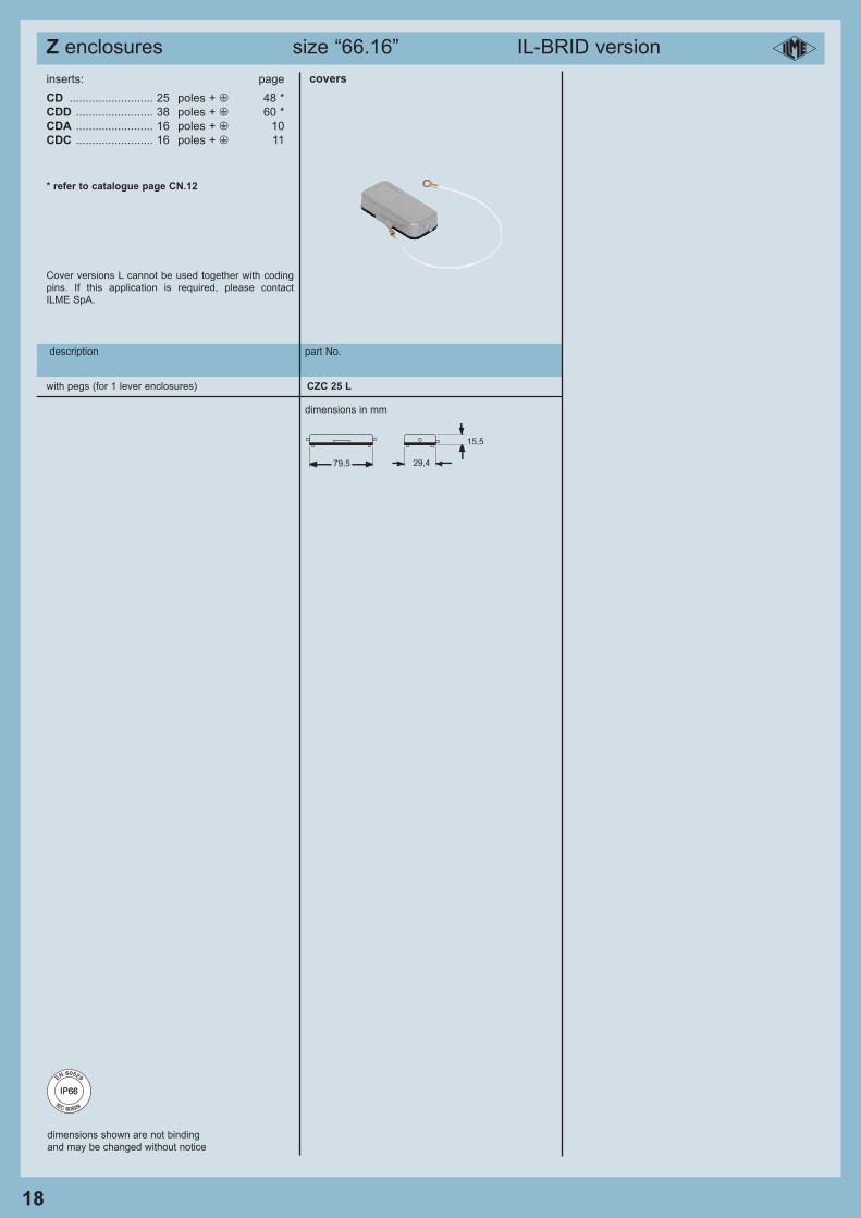
Z enclosures size “66.16” standard version i
IP66IP66
EN 60529
IEC 60529
dimensions shown are not binding
and may be changed without notice
inserts: page
CD .......................... 25 poles + m 48 *
CDD ........................ 38 poles + m 60 *
CDA ........................ 16 poles + m 10
CDC ........................ 16 poles + m 11
* refer to catalogue page CN.12
Cover versions L cannot be used together with coding
pins. If this application is required, please contact
ILME SpA.
description part No.
covers
dimensions in mm
18
15,5
79,5 29,4
Z enclosures size “66.16” IL-BRID version i
IP66IP66
EN 60529
IEC 60529
with pegs (for 1 lever enclosures) CZC 25 L

Notes i
ILME designs and manufactures complete solutions for heavy duty electrical power connections.
The connector (although offered to the user as a variety of elements, usually inserts and enclosures, to allow the
selection of the ideal combination) has been designed as a single part and tested to be compliant with the essential
safety requirements of the EU Low Voltage Directive 2006/95/EC and in particular the EN 61984 standard.
The design of this “modular” system guarantees that every approved combination of inserts, enclosures and accessories
cannot result as improper.
The products in this catalogue alone cannot guarantee the best functionality upon installation, as this depends also on
their correct “installation into service” which must be performed in compliance with the applicable system safety
standards and according to the “rule of the art”.
Therefore the effectiveness of the installation of the connector depends on the choices of the end user who must also
take into account the following safety requirements.
Connectors must not be connected or disconnected when live or under load.
After wiring the inserts it is necessary to verify the continuity of the protective earth connections.
The correct coupling of the inserts is guaranteed only if they are installed (with the four fixing screws supplied) inside the
corresponding enclosures or onto compatible accessories in this catalogue. I.L.M.E. SpA is not responsible for any
different application.
Wiring of screw-type terminal connections must be carried out applying the correct tightening torque in order to avoid
false contacts or damage to the conductor, the screw or the terminal.
Crimping tools and contacts used should preferably be supplied by the same manufacturer to avoid difficulties with the
insertion and retention of the contacts themselves.
Correct wiring of spring-clamp connection inserts is guaranteed only when the correct screwdriver indicated in the
specific catalogue, or possibly on the insert, is used.
Avoid forcing the contacts during connection and disconnection.
Connectors must be coupled and uncoupled in the axial direction with respect to the contacts, without bending and pulling
the attached conductor bundles or cables.
Installation of two inserts side by side, in enclosures with two bays, must respect the polarity drawing marked on the
insert (or the contact-side view, as shown in this catalogue) to avoid inverted coupling.
The installation of two or more identical connectors side by side is recommended only with the use of coding pins in
order to avoid mismatched couplings.
In order to keep the declared degree of protection (IP code), enclosures must be completed with cable glands and/or
other accessories with at least an equal protection rating.
Moreover, the IP protection rating (according to EN 60529) is guaranteed when the enclosures, complete with inserts,
are coupled and locked with their locking levers (or devices).
Finally, Please note:
- ILME cannot be held responsible for individual components in uses other than those described in this catalogue.
- ILME cannot be held responsible for incorrect connector selection in relation to the environmental conditions of the
application (e.g.: influence of ambient temperature, moisture, environmental pollution, etc.).
Connector inserts and their enclosures are generally compatible with similar/equivalent products from other
manufacturers, according to the last samples tested.
Full compatibility cannot be guaranteed in the event of technical changes made by other manufacturers. In particular,
maximum performance of IP68 enclosures (Series CG) cannot be guaranteed when coupled with other manufacturers’
products.
I.L.M.E. SpA takes no responsibility in verifying whether the components herein contained comply with any specific
regulations of fields of application.
IMPORTANT NOTES i
Sales organization
Subsidiaries
France
Germany
United Kingdom
Sweden and Nordic countries
Japan
China
ILME FRANCE S.A.R.L.
Rue Roland Garros - BP 125
Parc d'Activités de l'Aéroport
42163 Andrézieux-Bouthéon
☎ +33 (0) 4 77 36 23 36 - fax +33 (0) 4 77 36 97 97
e-mail: [email protected] - www.ilme.fr
ILME GmbH
Max-Planck-Straße 12 - 51674 Wiehl
☎ +49 (0)2261 - 7955-0
fax +49 (0)2261 - 7955-5 (Auftragsannahme) - +49 (0)2261 - 7955-9 (Vertrieb)
e-mail: [email protected] - www.ilme.de
ILME UK LIMITED
50 Evans Road, Venture Point
Speke, Merseyside L24 9PB
☎ +44 (0) 151 3369321 - fax +44 (0) 151 3369326
e-mail: [email protected] - www.ilmeuk.co.uk
ILME NORDIC AB
Transportvägen 18
24642 Löddeköpinge (Sweden)
☎ +46 46 18 28 00 - fax +46 46 18 28 10
e-mail: [email protected] - www.ilme.se
ILME JAPAN CO., LTD.
Kobe International Business Center 511 - 650-0047, 5-2, 5 - Chome,
Minatojima Minami-Machi - Chuo-Ku, Kobe Japan
☎ +81 7830 22005 - fax +81 7830 22060
www.ilmejapan.co.jp
ILME CHINA REP. OFFICE
Room 201 Universal Centre, no. 175 XiangYan NanLu, - 200031 Shanghai
☎ +86 - 21 - 62489961 - fax +86 - 21 - 62489961
www.ilmechina.com
Head office
I.L.M.E. SpA
via Marco Antonio Colonna, 9
20149 Milano - Italy
☎ +39 02345605.22 - fax +39 0233105813
www.ilme.com
i

w w w . i l m e . c o m
ca
talo
gu
es
XD
G IL
314-E
d. 03/2
014


