64

PG rev. 00 pag. 1The data specified into the catalogue are for product description purpose only and must not be interpreted as warranted characteristic in legal sense. Italgroup reserves the right to implement modifications without notice.
La famiglia di riduttori epicicloidali PG è offerta al mercato in 21 grandezze di base, selezionate in funzione dei momenti torcenti che possono essere trasmessi all’albero di uscita, che vanno da 0.05 kNm fino a 65 kNm. La modularità del prodotto permette l’accoppiamento ai riduttori epicicloidali di coppie coniche, riduttori vite senza fine, freni idraulici, diversi tipi di alberi di ingresso, nonchè di flange per l’accoppiamento diretto a motori idraulici o elettrici. Un altro grande vantaggio derivante dalla modularità dei riduttori epicicloidali è la possibilità del montaggio in serie di stadi di differenti grandezze, in modo da ottenere una vastissima gamma di rapporti di riduzione. La gamma di prodotti offre rapporti di riduzione da 3:1 a 7:1 per i riduttori a singolo stadio fino a 10.000:1 e oltre per i riduttori a 5 stadi di riduzione. Le diverse opzioni di albero e flangiatura in uscita semplificano l’installazione del riduttore su applicazioni mobili e impianti fissi industriali.
CARATTERISTICHE TECNICHE La conoscenza e l’esatta interpretazione dei dati riportati sul presente catalogo sono condizione indispensabile per la scelta e l’impiego corretto dei prodotti presentati. È importante quindi definire alcuni parametri caratteristici: RAPPORTO DI TRASMISSIONE iÈ il valore effettivo del rapporto tra la velocità di entrata n1 e la velocità di uscita n2. Viene indicato per ogni tipo di riduttore nella relativa scheda tecnica. VELOCITÀ MASSIMA IN ENTRATA n1max [min-1] Rappresenta il valore massimo accettabile per ogni grandezza di riduttore, in condizioni di funzionamento intermittente. Per applicazioni in servizio continuo o per velocità superiori a quelle indicate, il Servizio Tecnico Commerciale è a disposizione per ulteriori chiarimenti. I valori della velocità massima in entrata per ogni tipo di riduttore sono illustrati nelle singole schede tecniche. RENDIMENTO Nella trasmissione epicicloidale, il rendimento è generalmente elevato, mediamente 0,97- 0,98 per ogni stadio di riduzione. Questo dato indicativo si riduce nel caso di funzionamenti a velocità elevate o nel caso di riduttori in versione angolare. COPPIA CONTINUA Mc [kNm] È quella coppia per cui il valore delle sollecitazioni sugli ingranaggi è pari al valore limite secondo le norme internazionali ISO 6336. Questo valore convenzionale corrisponde ad una durata di vita teorica illimitata degli ingranaggi, tenendo conto sia della sollecitazione a flessione che della resistenza superficiale del dente (pressione di Hertz).
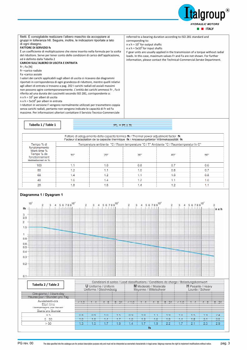
Ai fini della scelta del riduttore questo valore va posto in riferimento alla COSTANTE DI DURATA nxh espressa nel Diagramma 1 dove: n = velocità in uscita (min-1) h = durata di funzionamento (ore). Per semplicità di consultazione, nella scheda tecnica di prodotto sono riportati i valori di Mc corrispondenti ad un valore n2xh prefissato. COPPIA MASSIMA Mmax [kNm] È il valore massimo di coppia che il riduttore può trasmettere per breve tempo senza che si verifichino danneggiamenti ai suoi componenti interni ed alla sua struttura. Tale valore deve essere considerato come una coppia massima dovuta a picchi o spunti di avviamento e mai come coppia di lavoro; il valore Mmax deve inoltre essere opportunamente valutato in quegli azionamenti che comportano un elevato numero di avviamenti o inversioni. Il valore Mmax è indicato nelle schede tecniche di prodotto. TEMPERATURA DI FUNZIONAMENTO Le temperature dell’olio a cui i riduttori possono funzionare sono quelle comprese tra -20°C e + 90°C. Temperature al di fuori di questa fascia possono essere accettate se si prevedono particolari accorgimenti relativi ai tipi di lubrificante e di guarnizioni utilizzati. Tali accorgimenti possono essere decisi caso per caso, d’accordo con il Servizio Tecnico-Commerciale.POTENZA TERMICA Pt [kW] È la potenza massima trasmissibile dal riduttore in funzionamento continuo con lubrificazione normale a sbattimento, senza che l’olio superi la temperatura di 90°C. I valori di Pt riportati nelle singole schede tecniche di prodotto sono valori massimi espressi alle seguenti condizioni di impiego: • servizio continuo• velocità n1 = 1500 min- • olio ISO VG 150 • posizione di montaggio orizzontale • temperatura ambiente 20°C.
Qualora la potenza richiesta ecceda i valori indicati nella scheda tecnica
PG planetary gear units are divided into 21 basic groups depending on the different torques that are to be transmitted to the output shaft, which can vary from 0.05 to 65 kNm. In fact, the product modular construction permits the coupling of bevel gears, worm gears, hydraulic brakes and a variety of input shafts to the planetary units, as well as providing for a wide choise of coupling flanges for hydraulic or electric motors. Another advantage offered by the modular construction technique of the planetary gear units is the possibility to mount a series of stages of different sizes in order to obtain a vast range of reduction ratios. The product range provides reduction ratios from 3:1 to 7:1 on a single stage unit up to 10.000:1 and more on a 5 stage unit. The wide selection of output shafts and flanges simplifies the reduction unit mounting operation on industrial machinery or plants. GENERAL TECHNICAL INFORMATION The knowledge and correct interpretation of the information given in this catalogue are necessary starting-points for the best selection and use of the products. It is important to determine some distinctive parameters such as: REDUCTION RATIO iThis is the ratio of input speed n1 to output speed n2. The value for each planetary gear is shown in the relative technical card. MAXIMUM INPUT SPEED n1max [min-1] This is the maximum speed allowed for each size of planetary gear under conditions of intermittent work. In continuous duty or speeds greater than the onesindicated, please contact the Technical-Commercial Service Department. Maximum input values for each type of planetary gear are depicted in the single technical card. EFFICIENCY The efficiency is usually high in planetary transmission; i.e., the average value ranges between 0.97 and 0.98 for each reduction stage. This approximate value decreases under conditions of high speed or in applications with bevel gears. CONTINUOUS TORQUE Mc [kNm] This is the torque value related to the maximum value of the stress on the gears according to the international standards ISO 6336. This conventional torque value corresponds to the unlimited theoretic life of the gears, taking into consideration the bending stress as well as the surface strength of the tooth (Hertz pressure).
In regard to the selection of the planetary gear, this value represents the CONSTANT OF LIFETIME nxh as shown in Curve 1 where: n = output speed (min-1) h = working time (hours) In order to simplify your consultation, the single product technical cards show the Mc values referring to a fixed n2xh value. MAXIMUM TORQUE Mmax [kNm] This is the maximum output torque that the planetary unit can transmit in a short time without causing damage to the internal components and structure. This value must be considered as the maximum output torque due to working or starting peaks and never as the continuous working torque. It also must be carefully evaluated in those applications with a high number of starts or setting ups. The Mmax value is shown in the single product technical cards. WORKING TEMPERATURE The working oil temperature of the planetary gears should range between -20°C and + 90°C. Temperatures falling outside this range could be accepted only if special lubricants and gaskets are used. For further information, please contact the Technical-Commercial Service Department.THERMAL POWER Pt [kW] The thermal power is the maximum power the planetary unit can transmit in continuous duty with normal turbolence lubrication and without exceeding an oil temperature of 90°C. The Pt values shown in the single product technical card indicate the maximum values at the following duty conditions: • continuous duty • speed n1 = 1500 min-1 • oil ISO VG 150 • horizontal mounting position • room temperature 20°C.
If the required power exceeds the values indicated in the planetary gear technical card, a lubricant cooling system is needed. For foot mounted reduction units (from PG 100 serie to PG 1600 serie) the Pt value can be increased by 15%. If the duty characteristics differ, you can apply a corrective factor fk to the Pt values as indicated in the following Table 1: NOTE. Please note that the Pt refers to the power actually transmitted
pag. 2 PG rev. 00The data specified into the catalogue are for product description purpose only and must not be interpreted as warranted characteristic in legal sense. Italgroup reserves the right to implement modifications without notice.
del riduttore sarà necessario prevedere un sistema di raffreddamento del lubrificante. Per i riduttori con piedi (dalla grandezza PG 100 alla grandezza PG 1600) il valore di Pt può essere incrementato del 15%. Nel caso le caratteristiche di impiego siano diverse, si può applicare ai valori di Pt un fattore correttivo fk, come indica la Tabella 1, di seguito riportata:
N.B. Si noti che la Pt è riferita alla potenza effettivamente trasmessa dal riduttore, da non confondere quindi con la potenza del motore su di esso installato, che per vari motivi potrebbe essere superiore. Per ulteriori dettagli si prega di contattare il Servizio Tecnico-Commerciale.
NORME GENERALI PER L’INSTALLAZIONE E LA MANUTENZIONE Per garantire un buon funzionamento dei riduttori ed una miglior durata nel tempo è necessario un corretto accoppiamento alla struttura cui viene fissato il gruppo. Pertanto le superfici di tale struttura dovranno essere lavorate con centraggi in H8 ed in modo da garantire un’ottima planarità e perpendicolarità con l’asse del riduttore. Per il fissaggio del riduttore usare la bulloneria indicata sotto ogni disegno nelle schede tecniche di prodotto. Usare inoltre tutti i fori di fissaggio previsti sulle flange dei riduttori. Per gruppi installati all’aperto si consiglia, dove possibile, di proteggere i riduttori dalle intemperie, di trattarli con sistemi anticorrosivi e di proteggere i paraoli con grasso idrorepellente. Nelle applicazioni in cui possono verificarsi sovraccarichi accidentali tali da compromettere l’integrità della trasmissione, occorre prevedere un sistema di sicurezza (idraulico, meccanico) per salvaguardare il riduttore. L’abbinamento fra riduttori e motori, principalmente elettrici o idraulici, viene normalmente fatto mediante flangiatura diretta quando non si presentano particolari condizioni di criticità, che possono provocare danni dopo l’installazione. A tale proposito, ove è richiesto di installare motori molto pesanti, oltre i 100 Kg, consigliamo di contattare il nostro Servizio Tecnico-Commerciale, per meglio valutare l’applicazione in funzione della posizione di montaggio. In alternativa, si consiglia un montaggio separato dei due particolari collegati mediante giunto o pulegge. GRUPPI CON FISSAGGIO A FLANGIA AVANZATA O SENZA FLANGIA Riduttori con albero lentomaschio (M-P) Per tali gruppi, quando i carichi sono superiori del 50% rispetto a quelli indicati nei grafici riportati nelle singole schede di prodotto, si consiglia di utilizzare entrambi i centraggi previsti sulla scatola lato uscita. In tutti i casi, invece, devono essere utilizzati i centraggi previsti sugli alberi scanalati, soprattutto quando vengono montati dei pignoni dentati. Nelle applicazioni dove si verificano condizioni di forti carichi esterni agenti contemporaneamente sia sull’uscita che sull’entrata, si consiglia di contattare il nostro Servizio Tecnico-Commerciale. Riduttori con albero lento femmina (F) Per la tipologia di costruzione questi riduttori sono idonei alla trasmissione della pura coppia. Occorre quindi curare particolarmente la coassialità e l’ortogonalità nel collegamento con l’albero condotto. Riduttori a basamento con piedi (CPC) Anche per questi gruppi occorre che siano verificate le condizioni di fissaggio relative a coassialità ed ortogonalità già elencate all’inizio di questo capitolo. Occorre inoltre controllare adeguatamente l’allineamento del gruppo con la macchina da movimentare. Se si hanno dei dubbi sulla perfetta riuscita di tale operazione, utilizzare un collegamento non rigido fra riduttore e macchina, ad esempio un giunto elastico. Durante l’installazione considerare che il riduttore così montato non deve essere soggetto a fenomeni di vibrazione. Riduttori per montaggio pendolare (FS) Per l’installazione di questi riduttori si prescrive l’applicazione di un braccio di reazione che rispetti le lunghezze minime riportate a disegno per ogni singolo gruppo. Inoltre, si consiglia di ammortizzare il vincolo di reazione con elementi in gomma e/o ammortizzatori. In caso di applicazione di motori molto pesanti o di montaggio con cinghia sul lato entrata, contattare il nostro Servizio Tecnico-Commerciale per verificare l’installazione. In questi casi si producono, infatti, carichi esterni che, aggiungendosi a quelli della trasmissione, possono ridurre sensibilmente la vita dei cuscinetti, compromettere l’efficacia del serraggio dell’anello calettatore o influire sulla resistenza dell’albero. Per garantire un efficiente accoppiamento riduttore-utente, occorre sgrassare opportunamente la superficie interna dell’albero del riduttore e il relativo albero maschio di accoppiamento. Per un corretto serraggio dell’anello calettatore si raccomanda di “stringere” le viti in modo graduale ed uniforme, con sequenza continua. Per la rimozione, occorre svitare gradualmente le viti nello stesso modo in cui sono state avvitate, cioè con sequenza continua e graduale. Si consiglia di far compiere 1/3 di giro ad ogni vite nella prima sequenza di allentamento, in modo da evitare eventuali intraversamenti. Procedere poi allo sbloccaggio totale, ma sempre gradualmente e senza arrivare all’estrazione totale delle viti dai
by the planetary gear unit. Do not mistake it with the power of the motor mounted on it which for various reasons could be greater. For further details please contact the Technical-Commercial Service Department. GENERAL MOUNTING AND MAINTENANCE INSTRUCTIONS In order to ensure proper running and long life, the planetary unit must be mounted correctly. Always ensure that all mounting faces are flat and that the axis of the holes for spigot, which must have a tolerance H8, are perpendicular to the mounting face. To fasten gear unit use the bolt and nuts shown under each technical drawings in the product technical cards. Make sure that all the fixing holes on the flanges are used. We recommed to protect the gear units mounted in open air from bad weather by treating them with anticorrosive agents and to protect the oil seals with water-repellent grease. In operations in which there could be malfunctions due to accidental overloading a mechanical or hydraulic safety device must be used in order to safeguard the transmission. The assembly of the gear unit to the motors, electric or hydraulic, is usually done by means of direct flanges when no particularly critical conditions exist which could cause damage after installation. In connection with this, where the installation of heavy motors (over Kg 100) is required, please get in touch with our Technical-Commercial service Department, to evaluate the proper mounting position. In alternative, we suggest to separately mount the two units and to connect them by means of a coupling or pulley. UNITS WITH FLANGE CLAMPING OR WITHOUT FLANGE MOUNTING Planetary units with male output shaft (M-P) For these units, when the loads are 50% greater than the ones indicated in the single product technical card, we suggest the use of both spigots in the side flange. In all other cases, especially when toothed pinions are mounted, both spigots on splined output shafts must be used. In applications where heavy external load conditions simultaneously acting on the output and input exist, please contact our Technical-Commercial Service Department. Planetary units with female output shaft (F) These planetary units cannot accept external loads in any direction. Therefore always ensure that the shaft is concentric and in-line with the axis of the driven shaft. Foot mounted planetary units (CPC) The fastening conditions with respect to the concentricy and alignment as discussed in the beginning of this section, apply also to these units. Ensure that the unit is properly aligned with the machine to be operated. Should you have any doubts about the outcome of this operation, connect a flexible coupling between the planetary unit and the machine. Ensure that the mounted gear unit is not subject to vibrations. Reduction gears for shaft mounting (FS) Before installing these planetary units, you must prepare the torque arm by respecting the minimum lengths as shown on the drawing for each single unit. Furthermore, we recommend to cushion the reaction constraint using rubber elements and/or shock absorbers. For a correct application in case of particular mounting conditions due to the use of very heavy motors or to heavy radial load on the input, please contact our Technical –Commercial Service Department. These particular load conditions, together with the rotation reaction torque, could cosiderably reduce the lifetime of the bearings, and compromise the tightening of the shrink disc or affecting the shaft resistance. Before tightening the shrink disc, properly degrease the internal surface of the planetary unit shaft and its coupling male shaft. Then proceed to tighten the screws in a gradual and uniform manner without discontinuance. To remove the unit, gradually, unscrew the screws in the same order that you fasten them; i.e., without discontinuance. We advise to give each screw one third turn during the first loosening sequence in order to avoid possible misalignments. Then proceed to completely unfasten the unit, always in a gradual manner without completely removing the screw from the threads. We suggest to use tolerance h6 for the male shafts to be connected to the units. Furthermore, we suggest to follow the instructions shown besides each drawings. SERVICE FACTOR fs Service factor fs is a multiplication coefficient introduced into the formula for the selection of the planetary gear. In that formula it takes into account the application load conditions. It is defined in Table 2. OUTPUT AND INPUT SHAFT LOADS Fr ; Fa [N] Fr = radial load Fa = axial load The load values that output shafts can bear are indicated on the load curves shown on each gear box size; the load values relevant to input shafts are shown at page 202. Radial and axial loads are the maximum values permitted but must not occur simultaneously. The values of permitted loads Fr, Fa are
PG rev. 00 pag. 3The data specified into the catalogue are for product description purpose only and must not be interpreted as warranted characteristic in legal sense. Italgroup reserves the right to implement modifications without notice.
filetti. È consigliabile realizzare l’albero maschio da accoppiare ai gruppi in tolleranza h6. Seguire, inoltre, le indicazioni riportate a lato di ogni disegno. FATTORE DI SERVIZIO fs È un coefficiente di moltiplicazione che viene inserito nella formula per la scelta del riduttore. Serve per tener conto delle condizioni di carico dell’applicazione, ed è definito dalla Tabella 2 CARICHI SULL’ALBERO DI USCITA E ENTRATA Fr ; Fa [N] Fr =carico radiale Fa =carico assiale I valori dei carichi applicabili sugli alberi di uscita si ricavano dai diagrammi riportati in corrispondenza di ogni grandezza di riduttore, mentre quelli relativi agli alberi di entrata si trovano a pag. 202 I carichi radiali ed assiali massimi non possono agire contemporaneamente. L’entità dei carichi ammessi Fr , Fa è riferita ad una durata dei cuscinetti secondo ISO 281, corrispondente a: n x h = 105 per alberi di uscita n x h = 5x10⁶ per alberi in entrata I riduttori in versione F vengono normalmente utilizzati per trasmettere coppia senza carichi radiali, pertanto non vengono indicate le capacità di Fr ed Fa massime. Per informazioni ulteriori contattare il Servizio Tecnico‐Commerciale
referred to a bearing duration according to ISO 281 standard andcorresponding to: n x h = 105 for output shafts n x h = 5x10⁶ for input shafts F gear units are usually applied in the transmission of a torque without radial loads. In this case, maximum values Fr and Fa are not shown. For further information, please contact the Technical-Commercial.Service Department.
Diagramma 1 / Dyagram 1
Tabella 1 / Table 1
Tabella 2 / Table 2
pag. 4 PG rev. 00The data specified into the catalogue are for product description purpose only and must not be interpreted as warranted characteristic in legal sense. Italgroup reserves the right to implement modifications without notice.
PG rev. 00 pag. 5The data specified into the catalogue are for product description purpose only and must not be interpreted as warranted characteristic in legal sense. Italgroup reserves the right to implement modifications without notice.
pag. 6 PG rev. 00The data specified into the catalogue are for product description purpose only and must not be interpreted as warranted characteristic in legal sense. Italgroup reserves the right to implement modifications without notice.
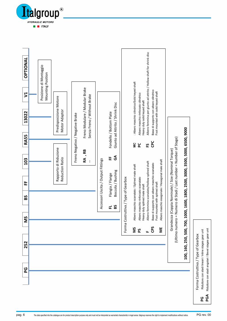
PG
252
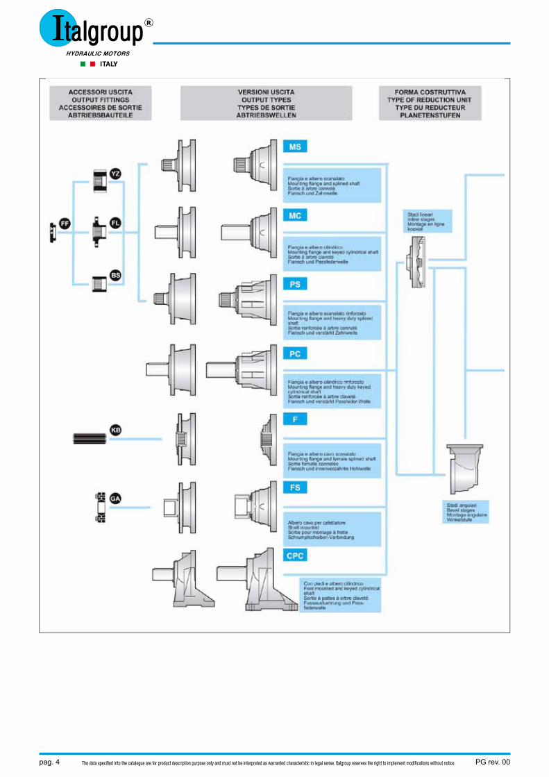
MS
BSFF
103
RA
5513
022
V1
OPT
IONAL
Form
a Co
struttiva / Type
of G
earbox
PG
Rid
utto
re c
on s
tadi
line
ari /
Inlin
e st
ages
gea
r uni
t
PGA
Rid
utto
re c
on s
tadi
ang
olar
i / B
evel
sta
ges
gear
uni
t
Grand
ezza (C
oppia Nom
inale) / Size (Nom
inal Torqu
e)
(Ultimo nu
mero = Num
ero di Stadi / Last n
umbe
r = Num
ber of Stage)
100, 160, 250, 500, 700, 1000, 1600, 1800, 2500, 3000, 3500, 5000, 6500, 9000
Form
a Co
struttiva / Type
of G
earbox
MS
Alb
ero
mas
chio
sca
nala
to /
Spl
ined
mal
e sh
aft
M
C
: Alb
ero
mas
chio
cili
ndric
o/S
olid
key
ed s
haft
PSA
lber
o m
asch
io ri
nfor
zato
sca
nala
to
PC
Alb
ero
mas
chio
rinf
orza
to c
ilind
rico
Hea
vy d
uty
splin
ed m
ale
shaf
t
Hea
vy d
uty
solid
key
ed s
haft
F
Albero femmina scanalato/Hollow splined
shaft
FS
Albero femmina pe
r giunto ad
attrito / Hollow shaft fo
r shrink
disc
CPS
Bas
e di
sup
porto
con
alb
ero
mas
chio
sca
nala
to
CP
C B
ase
di s
uppo
rto c
on a
lber
o ci
lindr
ico
Foot
mou
nted
with
spl
ined
sha
ft
Foot
mou
nted
with
sol
id k
eyed
sha
ft
ME
Alb
ero
mas
chio
esa
gona
le /
Hex
agon
al m
ale
shaf
t
Accessori Uscita
/ Outpu
t Fittings
FL
Flangia / Flange
FF
Fond
ello / Bottom Plate
BS
Boccola / Bu
shing
GA
Giunto ad
Attrito / Shrink Disc
Rapp
orto di Riduzione
Re
duction Ra
tio
Fren
o Negativo / Negative Brake
RA , RB
Fren
o Mod
ulare / Mod
ular Brake
‐‐
Senza Fren
o / With
out B
rake
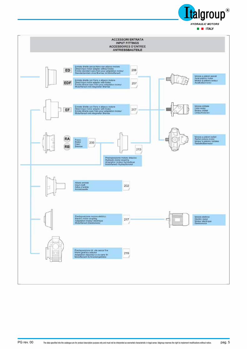
Pred
ispo
sizion
e Motore
Motor Adaptor
Posizion
e di M
ontaggio
Mou
nting Po
sitio
n
PG rev. 00 pag. 7The data specified into the catalogue are for product description purpose only and must not be interpreted as warranted characteristic in legal sense. Italgroup reserves the right to implement modifications without notice.
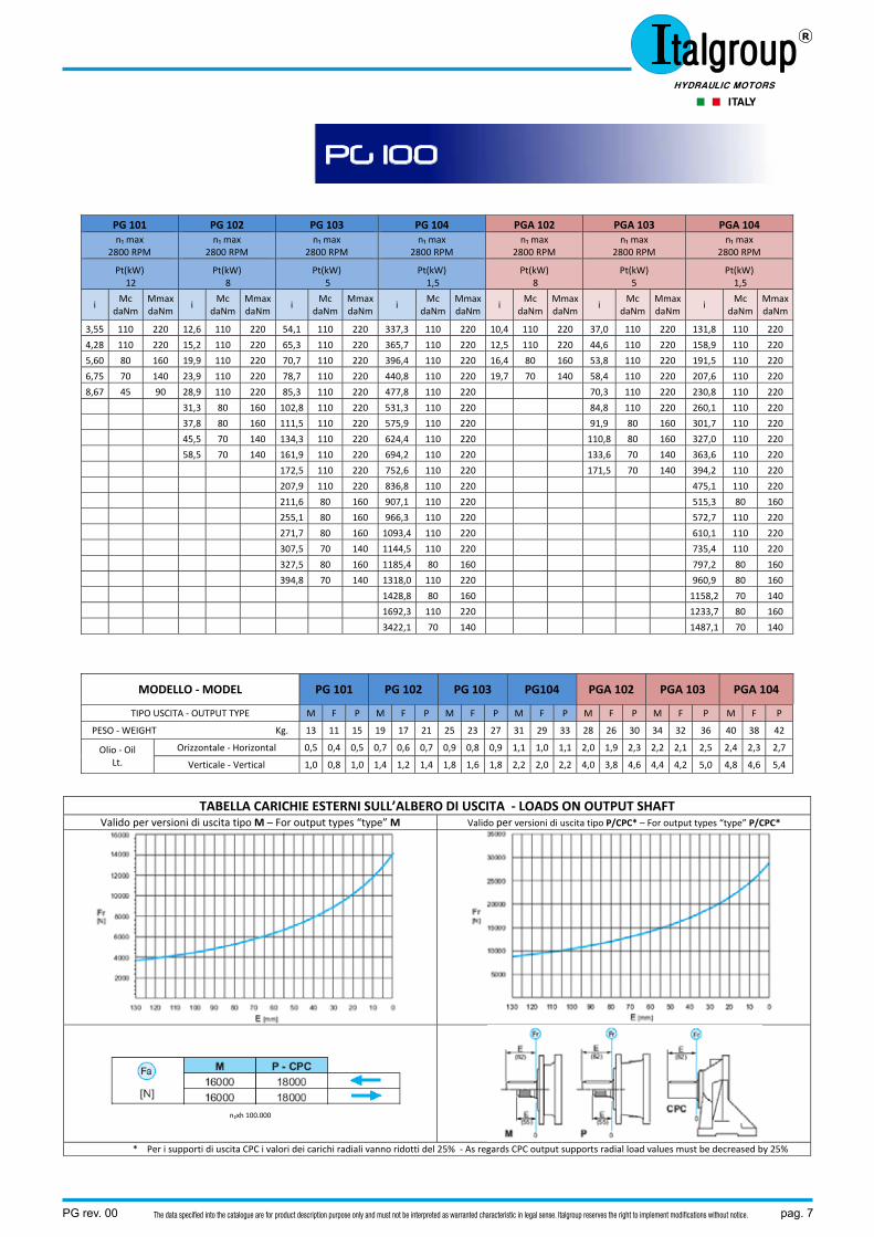
PG 101 PG 102 PG 103 PG 104 PGA 102 PGA 103 PGA 104 n₁ max
2800 RPM n₁ max
2800 RPM n₁ max
2800 RPM n₁ max
2800 RPM n₁ max
2800 RPM n₁ max
2800 RPM n₁ max
2800 RPM
Pt(kW) 12
Pt(kW) 8
Pt(kW) 5
Pt(kW) 1,5
Pt(kW) 8
Pt(kW) 5
Pt(kW) 1,5
i Mc
daNm Mmax daNm
i Mc
daNm Mmax daNm
i Mc
daNm Mmax daNm
i Mc
daNmMmax daNm
i Mc
daNmMmax daNm
i Mc
daNm Mmax daNm
i Mc
daNmMmax daNm
3,55 110 220 12,6 110 220 54,1 110 220 337,3 110 220 10,4 110 220 37,0 110 220 131,8 110 220
4,28 110 220 15,2 110 220 65,3 110 220 365,7 110 220 12,5 110 220 44,6 110 220 158,9 110 220
5,60 80 160 19,9 110 220 70,7 110 220 396,4 110 220 16,4 80 160 53,8 110 220 191,5 110 220
6,75 70 140 23,9 110 220 78,7 110 220 440,8 110 220 19,7 70 140 58,4 110 220 207,6 110 220
8,67 45 90 28,9 110 220 85,3 110 220 477,8 110 220 70,3 110 220 230,8 110 220
31,3 80 160 102,8 110 220 531,3 110 220 84,8 110 220 260,1 110 220
37,8 80 160 111,5 110 220 575,9 110 220 91,9 80 160 301,7 110 220
45,5 70 140 134,3 110 220 624,4 110 220 110,8 80 160 327,0 110 220
58,5 70 140 161,9 110 220 694,2 110 220 133,6 70 140 363,6 110 220
172,5 110 220 752,6 110 220 171,5 70 140 394,2 110 220
207,9 110 220 836,8 110 220 475,1 110 220
211,6 80 160 907,1 110 220 515,3 80 160
255,1 80 160 966,3 110 220 572,7 110 220
271,7 80 160 1093,4 110 220 610,1 110 220
307,5 70 140 1144,5 110 220 735,4 110 220
327,5 80 160 1185,4 80 160 797,2 80 160
394,8 70 140 1318,0 110 220 960,9 80 160
1428,8 80 160 1158,2 70 140
1692,3 110 220 1233,7 80 160
3422,1 70 140 1487,1 70 140
MODELLO ‐ MODEL PG 101 PG 102 PG 103 PG104 PGA 102 PGA 103 PGA 104
TIPO USCITA ‐ OUTPUT TYPE M F P M F P M F P M F P M F P M F P M F P
PESO ‐ WEIGHT Kg. 13 11 15 19 17 21 25 23 27 31 29 33 28 26 30 34 32 36 40 38 42
Olio ‐ Oil Lt.
Orizzontale ‐ Horizontal 0,5 0,4 0,5 0,7 0,6 0,7 0,9 0,8 0,9 1,1 1,0 1,1 2,0 1,9 2,3 2,2 2,1 2,5 2,4 2,3 2,7
Verticale ‐ Vertical 1,0 0,8 1,0 1,4 1,2 1,4 1,8 1,6 1,8 2,2 2,0 2,2 4,0 3,8 4,6 4,4 4,2 5,0 4,8 4,6 5,4
TABELLA CARICHIE ESTERNI SULL’ALBERO DI USCITA ‐ LOADS ON OUTPUT SHAFT Valido per versioni di uscita tipo M – For output types “type” M Valido per versioni di uscita tipo P/CPC* – For output types “type” P/CPC*
n₂xh 100.000
* Per i supporti di uscita CPC i valori dei carichi radiali vanno ridotti del 25% ‐ As regards CPC output supports radial load values must be decreased by 25%
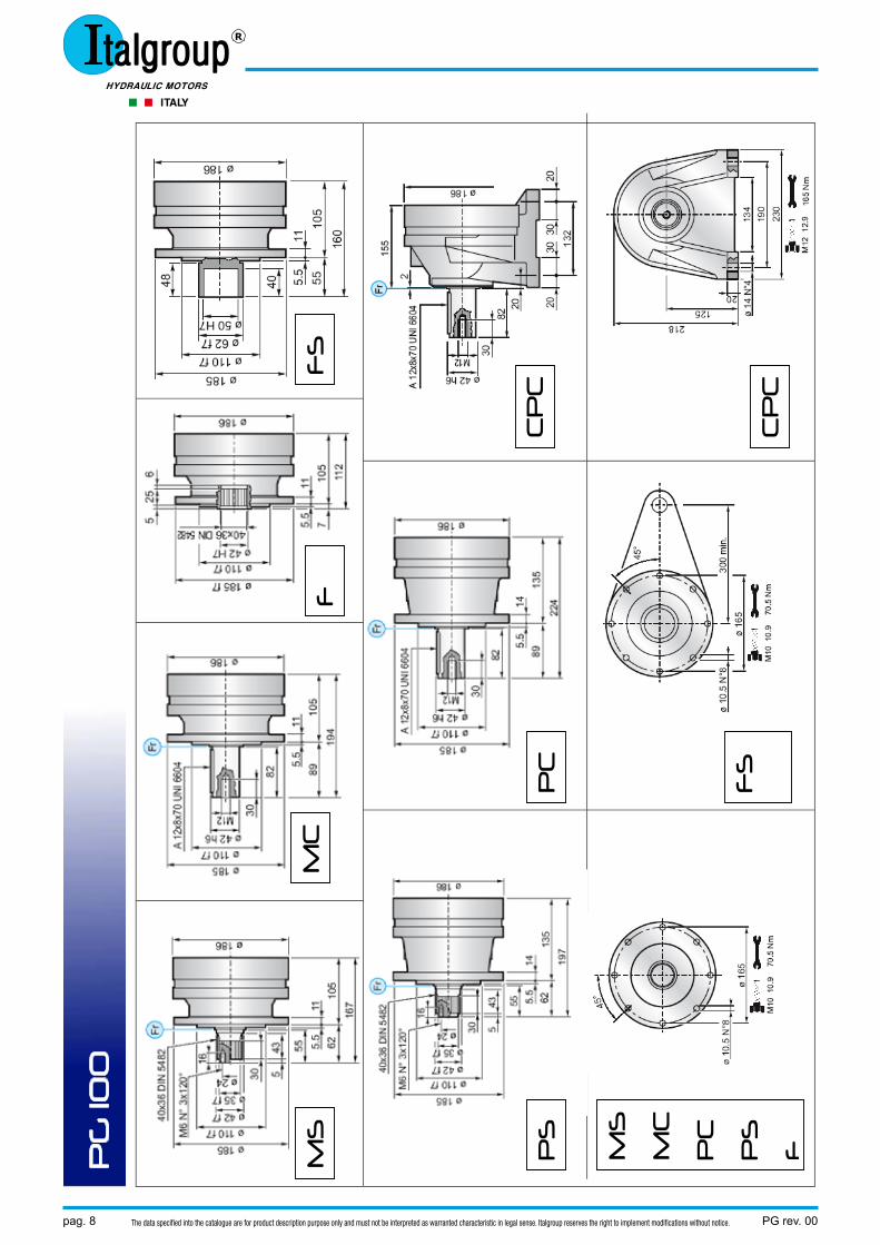
PG 100
pag. 8 PG rev. 00The data specified into the catalogue are for product description purpose only and must not be interpreted as warranted characteristic in legal sense. Italgroup reserves the right to implement modifications without notice.
PG
100
MS
M
C
F
FS
PS
P
C
CP
C
MS
MC
PC
PS
F
FS
C
PC
PG rev. 00 pag. 9The data specified into the catalogue are for product description purpose only and must not be interpreted as warranted characteristic in legal sense. Italgroup reserves the right to implement modifications without notice.
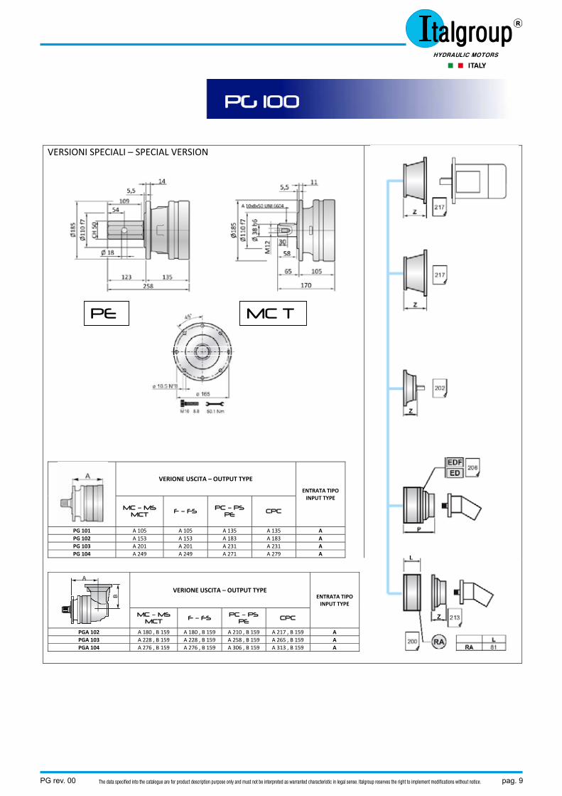
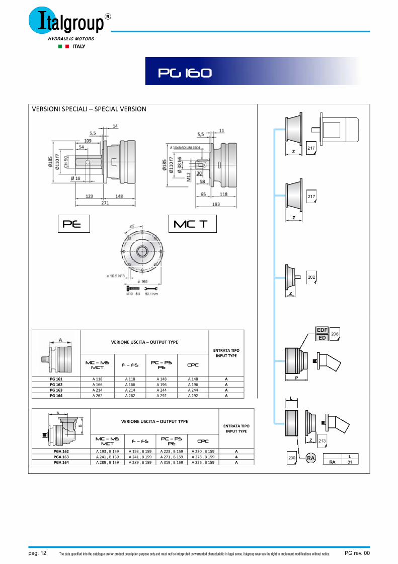
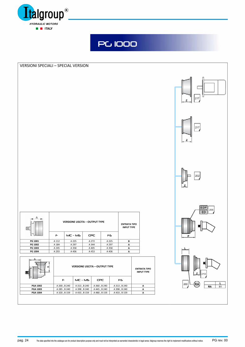
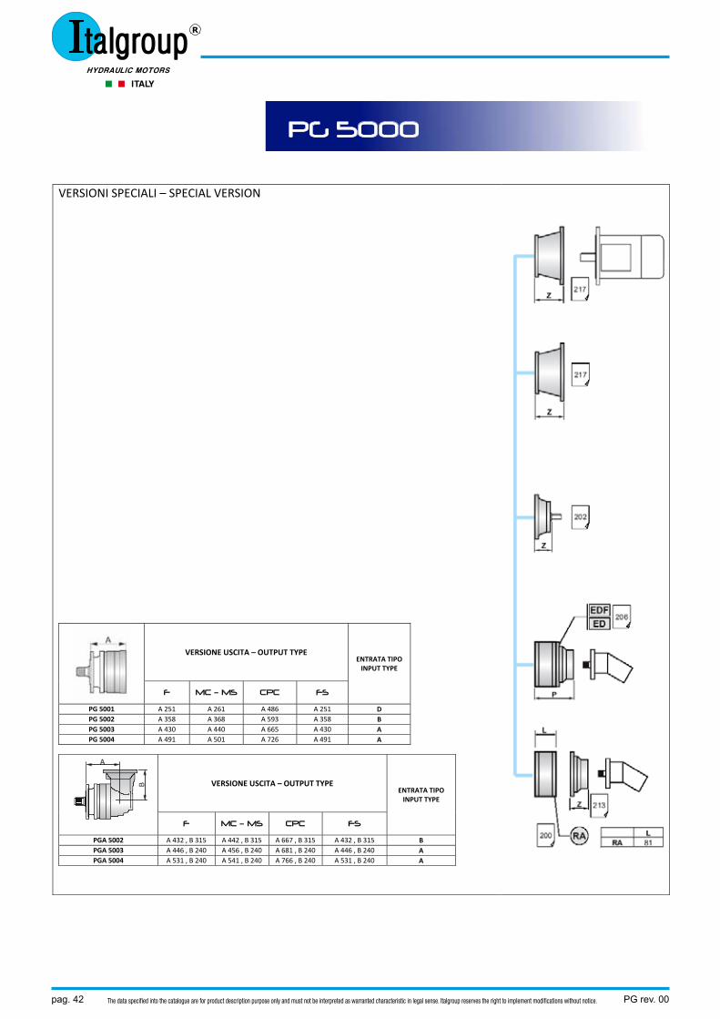
VERSIONI SPECIALI – SPECIAL VERSION
VERIONE USCITA – OUTPUT TYPE
ENTRATA TIPO INPUT TYPE
MC – MS MCT F – FS PC – PS
PE CPC
PG 101 A 105 A 105 A 135 A 135 A PG 102 A 153 A 153 A 183 A 183 A PG 103 A 201 A 201 A 231 A 231 A PG 104 A 249 A 249 A 271 A 279 A
VERIONE USCITA – OUTPUT TYPE ENTRATA TIPO INPUT TYPE
MC – MS MCT F – FS PC – PS
PE CPC
PGA 102 A 180 , B 159 A 180 , B 159 A 210 , B 159 A 217 , B 159 A PGA 103 A 228 , B 159 A 228 , B 159 A 258 , B 159 A 265 , B 159 A PGA 104 A 276 , B 159 A 276 , B 159 A 306 , B 159 A 313 , B 159 A
MC T PE
PG 100
pag. 10 PG rev. 00The data specified into the catalogue are for product description purpose only and must not be interpreted as warranted characteristic in legal sense. Italgroup reserves the right to implement modifications without notice.
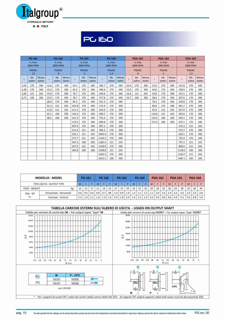
PG 161 PG 162 PG 163 PG 164 PGA 162 PGA 163 PGA 164 n₁ max
2800 RPM n₁ max
2800 RPM n₁ max
2800 RPM n₁ max
2800 RPM n₁ max
2800 RPM n₁ max
2800 RPM n₁ max
2800 RPM
Pt(kW) 12
Pt(kW) 8
Pt(kW) 5
Pt(kW) 1,5
Pt(kW) 8
Pt(kW) 5
Pt(kW) 1,5
i Mc
daNm Mmax daNm
i Mc
daNm Mmax daNm
i Mc
daNm Mmax daNm
i Mc
daNmMmaxdaNm
i Mc
daNmMmax daNm
i Mc
daNm Mmax daNm
i Mc
daNmMmaxdaNm
3,55 170 340 12,6 170 340 54.1 170 340 365.7 170 340 10,4 170 340 37,0 170 340 131.8 170 340
4,28 170 340 15,2 170 340 65.3 170 340 396.4 170 340 12,5 170 340 44,6 170 340 158.9 170 340
5,60 121 242 19,9 170 340 70.7 170 340 440.8 170 340 16,4 121 242 53,8 170 340 191.5 170 340
6,75 100 200 23,9 170 340 78.7 170 340 477.8 170 340 19,7 100 200 58,4 170 340 207.6 170 340
28,9 170 340 85.3 170 340 531.3 170 340 70,3 170 340 230.8 170 340
31,3 121 242 102.8 170 340 575.9 170 340 84,8 170 340 301.7 170 340
37,8 121 242 111.5 170 340 624.4 170 340 91,9 121 242 327.0 170 340
45,5 100 200 134.3 170 340 694.2 170 340 110,8 121 242 363.6 170 340
58,5 100 200 161.9 170 340 752.6 170 340 133,6 100 200 394.2 170 340
172.5 170 340 836.8 170 340 171,5 100 200 475.1 170 340
207.9 170 340 907.1 170 340 515.3 121 242
211.6 121 242 966.3 170 340 572.7 170 340
255.1 121 242 1093.4 170 340 610.1 170 340
271.7 121 242 1144.5 170 340 735.4 170 340
307.5 100 200 1185.4 121 242 797.2 121 242
327.5 121 242 1318.0 170 340 960.9 121 242
394.8 100 200 1428.8 121 242 1158.2 100 200
1692.3 170 340 1233.7 121 242
3422.1 100 200 1487.1 100 200
MODELLO ‐ MODEL PG 161 PG 162 PG 163 PG 164 PGA 162 PGA 163 PGA 164
TIPO USCITA ‐ OUTPUT TYPE M F P M F P M F P M F P M F P M F P M F P
PESO ‐ WEIGHT Kg. 15 13 17 21 19 23 27 25 29 33 31 35 30 28 32 36 34 38 42 40 44
Olio ‐ Oil Lt.
Orizzontale ‐ Horizontal 0.6 0.5 0.6 0.8 0.7 08 1.0 0.9 1.0 1.2 1.1 1.2 2.1 2.0 2.4 2.3 2.2 2.6 2.5 2.4 2.8
Verticale ‐ Vertical 1.2 1.0 1.2 1.6 1.4 1.6 2.0 1.8 2.0 2.4 2.2 2.4 4.2 4.0 4.8 4.6 4.4 5.2 5.0 4.8 5.6
TABELLA CARICHIE ESTERNI SULL’ALBERO DI USCITA ‐ LOADS ON OUTPUT SHAFT Valido per versioni di uscita tipo M – For output types “type” M Valido per versioni di uscita tipo P/CPC* – For output types “type” P/CPC*
n₂xh 100.000
* Per i supporti di uscita CPC i valori dei carichi radiali vanno ridotti del 25% ‐ As regards CPC output supports radial load values must be decreased by 25%
PG 160
PG rev. 00 pag. 11The data specified into the catalogue are for product description purpose only and must not be interpreted as warranted characteristic in legal sense. Italgroup reserves the right to implement modifications without notice.
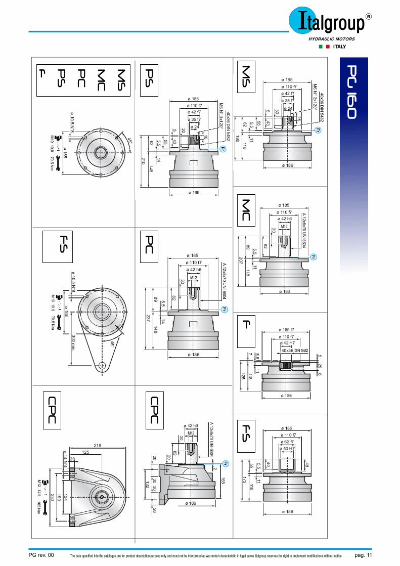
MS
M
C
F
FS
PS
P
C
CP
C
MS
MC
PC
PS
F
FS
C
PC
PG
160
pag. 12 PG rev. 00The data specified into the catalogue are for product description purpose only and must not be interpreted as warranted characteristic in legal sense. Italgroup reserves the right to implement modifications without notice.
VERSIONI SPECIALI – SPECIAL VERSION
VERIONE USCITA – OUTPUT TYPE
ENTRATA TIPO INPUT TYPE
MC – MS MCT F – FS PC – PS
PE CPC
PG 161 A 118 A 118 A 148 A 148 A PG 162 A 166 A 166 A 196 A 196 A PG 163 A 214 A 214 A 244 A 244 A PG 164 A 262 A 262 A 292 A 292 A
VERIONE USCITA – OUTPUT TYPE ENTRATA TIPO INPUT TYPE
MC – MS MCT F – FS PC – PS
PE CPC
PGA 162 A 193 , B 159 A 193 , B 159 A 223 , B 159 A 230 , B 159 A PGA 163 A 241 , B 159 A 241 , B 159 A 271 , B 159 A 278 , B 159 A PGA 164 A 289 , B 159 A 289 , B 159 A 319 , B 159 A 326 , B 159 A
MC T PE
PG 160
PG rev. 00 pag. 13The data specified into the catalogue are for product description purpose only and must not be interpreted as warranted characteristic in legal sense. Italgroup reserves the right to implement modifications without notice.
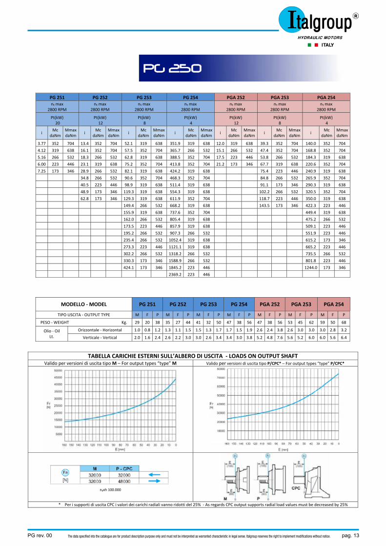
PG 251 PG 252 PG 253 PG 254 PGA 252 PGA 253 PGA 254 n₁ max
2800 RPM n₁ max
2800 RPM n₁ max
2800 RPM n₁ max
2800 RPM n₁ max
2800 RPM n₁ max
2800 RPM n₁ max
2800 RPM
Pt(kW) 20
Pt(kW) 12
Pt(kW) 8
Pt(kW) 4
Pt(kW) 12
Pt(kW) 8
Pt(kW) 4
i Mc
daNm Mmax daNm
i Mc
daNm Mmax daNm
i Mc
daNm Mmax daNm
i Mc
daNmMmax daNm
i Mc
daNmMmax daNm
i Mc
daNm Mmax daNm
i Mc
daNmMmax daNm
3.77 352 704 13.4 352 704 52.1 319 638 351.9 319 638 12.0 319 638 39.3 352 704 140.0 352 704
4.12 319 638 16.1 352 704 57.5 352 704 365.7 266 532 15.1 266 532 47.4 352 704 168.8 352 704
5.16 266 532 18.3 266 532 62.8 319 638 388.5 352 704 17.5 223 446 53.8 266 532 184.3 319 638
6.00 223 446 23.1 319 638 75.2 352 704 413.8 352 704 21.2 173 346 67.7 319 638 220.6 352 704
7.25 173 346 28.9 266 532 82.1 319 638 424.2 319 638 75.4 223 446 240.9 319 638
34.8 266 532 90.6 352 704 468.3 352 704 84.8 266 532 265.9 352 704
40.5 223 446 98.9 319 638 511.4 319 638 91.1 173 346 290.3 319 638
48.9 173 346 119.3 319 638 554.3 319 638 102.2 266 532 320.5 352 704
62.8 173 346 129.3 319 638 611.9 352 704 118.7 223 446 350.0 319 638
149.4 266 532 668.2 319 638 143.5 173 346 422.3 223 446
155.9 319 638 737.6 352 704 449.4 319 638
162.0 266 532 805.4 319 638 475.2 266 532
173.5 223 446 857.9 319 638 509.1 223 446
195.2 266 532 907.3 266 532 551.9 223 446
235.4 266 532 1052.4 319 638 615.2 173 346
273.3 223 446 1121.1 319 638 665.2 223 446
302.2 266 532 1318.2 266 532 735.5 266 532
330.3 173 346 1588.9 266 532 801.8 223 446
424.1 173 346 1845.2 223 446 1244.0 173 346
2369.2 223 446
MODELLO ‐ MODEL PG 251 PG 252 PG 253 PG 254 PGA 252 PGA 253 PGA 254
TIPO USCITA ‐ OUTPUT TYPE M F P M F P M F P M F P M F P M F P M F P
PESO ‐ WEIGHT Kg. 29 20 38 35 27 44 41 32 50 47 38 56 47 38 56 53 45 62 59 50 68
Olio ‐ Oil Lt.
Orizzontale ‐ Horizontal 1.0 0.8 1.2 1.3 1.1 1.5 1.5 1.3 1.7 1.7 1.5 1.9 2.6 2.4 3.8 2.6 3.0 3.0 3.0 2.8 3.2
Verticale ‐ Vertical 2.0 1.6 2.4 2.6 2.2 3.0 3.0 2.6 3.4 3.4 3.0 3.8 5.2 4.8 7.6 5.6 5.2 6.0 6.0 5.6 6.4
TABELLA CARICHIE ESTERNI SULL’ALBERO DI USCITA ‐ LOADS ON OUTPUT SHAFT Valido per versioni di uscita tipo M – For output types “type” M Valido per versioni di uscita tipo P/CPC* – For output types “type” P/CPC*
n₂xh 100.000
* Per i supporti di uscita CPC i valori dei carichi radiali vanno ridotti del 25% ‐ As regards CPC output supports radial load values must be decreased by 25%
PG 250
pag. 14 PG rev. 00The data specified into the catalogue are for product description purpose only and must not be interpreted as warranted characteristic in legal sense. Italgroup reserves the right to implement modifications without notice.
PG
25
0
MS
M
C
F
FS
PS
P
C
CP
C
MS
-MC
F
S
PS
-PC
F
PG rev. 00 pag. 15The data specified into the catalogue are for product description purpose only and must not be interpreted as warranted characteristic in legal sense. Italgroup reserves the right to implement modifications without notice.
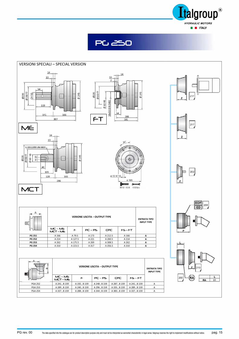
VERSIONI SPECIALI – SPECIAL VERSION
VERIONE USCITA – OUTPUT TYPE ENTRATA TIPO INPUT TYPE
MC – MS MCT - ME F PC – PS CPC FS - FT
PG 251 A 166 A 79.5 A 173 A 212.5 A 166 A PG 252 A 214 A 127.5 A 221 A 260.5 A 214 A PG 253 A 262 A 175.5 A 269 A 308.5 A 262 A PG 254 A 310 A 223.5 A 317 A 356.5 A 310 A
VERIONE USCITA – OUTPUT TYPE ENTRATA TIPO INPUT TYPE
MC – MS MCT - ME F PC – PS CPC FS – FT
PGA 252 A 241 , B 159 A 192 , B 159 A 248 , B 159 A 287 , B 159 A 241 , B 159 A PGA 253 A 289 , B 159 A 240 , B 159 A 296 , B 159 A 335 , B 159 A 289 , B 159 A PGA 254 A 337 , B 159 A 288 , B 159 A 344 , B 159 A 383 , B 159 A 337 , B 159 A
PG 250
FT
MCT
ME
pag. 16 PG rev. 00The data specified into the catalogue are for product description purpose only and must not be interpreted as warranted characteristic in legal sense. Italgroup reserves the right to implement modifications without notice.
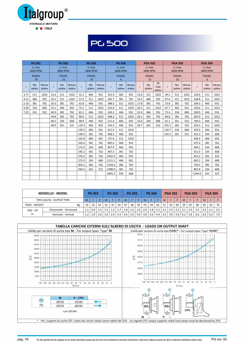
PG 501 PG 502 PG 503 PG 504 PGA 502 PGA 503 PGA 504 n₁ max
2800 RPM n₁ max
2800 RPM n₁ max
2800 RPM n₁ max
2800 RPM n₁ max
2800 RPM n₁ max
2800 RPM n₁ max
2800 RPM
Pt(kW) 20
Pt(kW) 15
Pt(kW) 10
Pt(kW) 6
Pt(kW) 15
Pt(kW) 10
Pt(kW) 6
i Mc
daNm Mmax daNm
i Mc
daNm Mmax daNm
i Mc
daNm Mmax daNm
i Mc
daNmMmaxdaNm
i Mc
daNm
M max daNm
i Mc
daNm Mmax daNm
i Mc
daNmMmax daNm
3.77 511 1022 13.4 511 1022 52.1 466 932 351.9 466 932 13.0 511 1022 39.3 511 1022 140.0 511 1022
4.12 466 932 16.1 511 1022 57.5 511 1022 365.7 381 762 14.2 466 932 47.4 511 1022 168.8 511 1022
5.16 381 762 18.3 381 762 62.8 466 932 388.5 511 1022 17.8 381 762 53.8 381 762 184.3 466 932
6.00 334 668 23.1 466 932 75.2 511 1022 413.8 511 1022 20.5 511 1022 67.7 466 932 220.6 511 1022
7.25 261 522 28.9 381 762 82.1 466 932 424.2 466 932 22.4 466 932 75.4 334 668 240.9 466 932
34.8 381 762 90.6 511 1022 468.3 511 1022 28.1 381 762 84.8 381 762 265.9 511 1022
40.5 334 668 98.9 466 932 511.4 466 932 32.6 334 668 91.1 261 522 290.3 466 932
48.9 261 522 119.3 466 932 554.3 466 932 39.7 261 522 102.2 381 762 320.5 511 1022
129.3 466 932 611.9 511 1022 118.7 334 668 350.0 466 932
149.4 381 762 668.2 466 932 143.5 261 522 422.3 334 668
155.9 466 932 737.6 511 1022 449.4 466 932
162.0 381 762 805.4 466 932 475.2 381 762
173.5 334 668 857.9 466 932 509.1 334 668
195.2 381 762 907.3 381 762 551.9 334 668
235.4 381 762 1052.4 466 932 615.2 261 522
273.3 334 668 1121.1 466 932 665.2 334 668
302.2 381 762 1318.2 381 762 735.5 381 762
330.3 261 522 1588.9 381 762 801.8 334 668
1845.2 334 668 1244.0 261 522
MODELLO ‐ MODEL PG 501 PG 502 PG 503 PG 504 PGA 502 PGA 503 PGA 504
TIPO USCITA ‐ OUTPUT TYPE M F P M F P M F P M F P M F P M F P M F P
PESO ‐ WEIGHT Kg. 33 25 42 41 32 50 47 38 56 53 44 62 51 43 60 59 50 68 65 56 74
Olio ‐ Oil Lt.
Orizzontale ‐ Horizontal 1.1 0.9 1.3 1.5 1.3 1.7 1.8 1.6 2.0 2.0 1.8 2.2 3.1 2.9 3.3 3.1 2.9 3.3 3.3 3.1 3.5
Verticale ‐ Vertical 2.2 1.8 2.6 3.0 2.6 3.4 3.6 3.2 4.0 4.0 3.6 4.4 4.2 3.8 4.6 6.2 5.8 6.6 6.6 6.2 7.0
TABELLA CARICHIE ESTERNI SULL’ALBERO DI USCITA ‐ LOADS ON OUTPUT SHAFT Valido per versioni di uscita tipo M – For output types “type” M Valido per versioni di uscita tipo P/CPC* – For output types “type” P/CPC*
n₂xh 100.000
* Per i supporti di uscita CPC i valori dei carichi radiali vanno ridotti del 25% ‐ As regards CPC output supports radial load values must be decreased by 25%
PG 500
PG rev. 00 pag. 17The data specified into the catalogue are for product description purpose only and must not be interpreted as warranted characteristic in legal sense. Italgroup reserves the right to implement modifications without notice.
PG
50
0
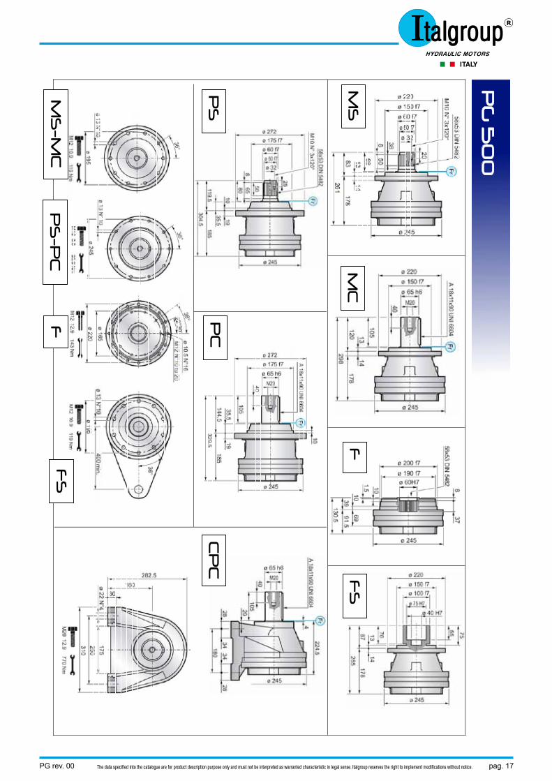
MS
M
C
F
FS
PS
P
C
CP
C
MS
-MC
F
S
PS
-PC
F
pag. 18 PG rev. 00The data specified into the catalogue are for product description purpose only and must not be interpreted as warranted characteristic in legal sense. Italgroup reserves the right to implement modifications without notice.
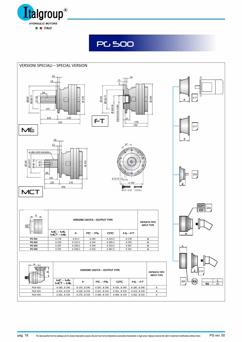
VERSIONI SPECIALI – SPECIAL VERSION
VERIONE USCITA – OUTPUT TYPE ENTRATA TIPO INPUT TYPE
MC – MS MCT - ME F PC – PS CPC FS - FT
PG 501 A 178 A 91.5 A 185 A 224.5 A 178 A PG 502 A 239 A 152.5 A 245 A 285.5 A 239 A PG 503 A 287 A 200.5 A 294 A 333.5 A 287 A PG 504 A 335 A 248.5 A 342 A 381.5 A 335 A
VERIONE USCITA – OUTPUT TYPE ENTRATA TIPO INPUT TYPE
MC – MS MCT – ME F PC – PS CPC FS – FT
PGA 502 A 280 , B 240 A 193 , B 240 A 287 , B 240 A 326 , B 240 A 280 , B 240 A PGA 503 A 314 , B 159 A 228 , B 159 A 321 , B 159 A 361 , B 159 A 314 , B 159 A PGA 504 A 362 , B 159 A 276 , B 159 A 369 , B 159 A 409 , B 159 A 362 , B 159 A
PG 500
FT
MCT
ME
PG rev. 00 pag. 19The data specified into the catalogue are for product description purpose only and must not be interpreted as warranted characteristic in legal sense. Italgroup reserves the right to implement modifications without notice.
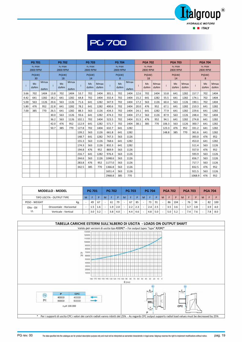
PG 701 PG 702 PG 703 PG 704 PGA 702 PGA 703 PGA 704 n₁ max
2800 RPM n₁ max
2800 RPM n₁ max
2800 RPM n₁ max
2800 RPM n₁ max
2800 RPM n₁ max
2800 RPM n₁ max
2800 RPM
Pt(kW) 30
Pt(kW) 18
Pt(kW) 14
Pt(kW) 8
Pt(kW) 18
Pt(kW) 14
Pt(kW) 8
i Mc
daNm
Mmax
daNm i
Mc daNm
Mmax
daNm i
Mc daNm
Mmax daNm
i Mc
daNm
Mmax
daNmi
Mc daNm
Mmax daNm
i Mc
daNm Mmax daNm
i Mc
daNmMmax daNm
3.66 702 1404 13.8 702 1404 53.7 702 1404 301.1 702 1404 12.6 702 1404 53.8 641 1282 157.7 702 1404
4.42 641 1282 18.2 641 1282 64.8 702 1404 332.4 702 1404 15.2 641 1282 55.5 641 1282 174.1 702 1404
5.00 563 1126 20.6 563 1126 71.6 641 1282 347.9 702 1404 17.2 563 1126 60.4 563 1126 190.1 702 1404
5.80 476 952 22.8 641 1282 78.2 641 1282 400.6 702 1404 20.0 476 952 67.1 641 1282 210.3 641 1282
7.00 385 770 26.5 641 1282 88.3 563 1126 434.3 702 1404 24.1 641 1282 77.9 641 1282 229.6 641 1282
30.0 563 1126 93.6 641 1282 474.3 702 1404 27.2 563 1126 87.9 563 1126 248.4 702 1404
36.2 563 1126 102.1 702 1404 523.5 702 1404 31.5 476 952 94.1 641 1282 274.8 641 1282
42.0 476 952 112.9 641 1282 571.7 702 1404 38.1 385 770 106.3 563 1126 300.7 641 1282
50.7 385 770 127.8 702 1404 632.7 641 1282 123.3 476 952 331.2 641 1282
139.2 563 1126 661.8 641 1282 148.8 385 770 361.6 641 1282
148.7 641 1282 747.3 563 1126 393.0 476 952
155.3 563 1126 768.6 641 1282 453.0 641 1282
174.3 563 1126 832.3 641 1282 511.4 563 1126
194.8 476 952 869.9 563 1126 557.0 476 952
216.7 641 1282 976.4 563 1126 593.9 563 1126
244.6 563 1126 1048.6 563 1126 656.7 563 1126
283.8 476 952 1177.0 563 1126 717.7 563 1126
342.5 385 770 1366.8 563 1126 832.5 476 952
1651.4 563 1126 921.5 563 1126
2968.8 385 770 1068.9 476 952
MODELLO ‐ MODEL PG 701 PG 702 PG 703 PG 704 PGA 702 PGA 703 PGA 704
TIPO USCITA ‐ OUTPUT TYPE M F P M F P M F P M F P M F P M F P M F P
PESO ‐ WEIGHT Kg. ‐ 49 67 ‐ 61 79 ‐ 67 85 ‐ 73 91 ‐ 86 104 ‐ 76 94 ‐ 82 100
Olio ‐ Oil Lt.
Orizzontale ‐ Horizontal ‐ 1.5 1.6 ‐ 1.9 2.0 ‐ 2.2 2.3 ‐ 2.4 2.5 ‐ 3.5 3.6 ‐ 3.7 3.8 ‐ 3.9 4.0
Verticale ‐ Vertical ‐ 3.0 3.2 ‐ 3.8 4.0 ‐ 4.4 4.6 ‐ 4.8 5.0 ‐ 5.0 5.2 ‐ 7.4 7.6 ‐ 7.8 8.0
TABELLA CARICHIE ESTERNI SULL’ALBERO DI USCITA ‐ LOADS ON OUTPUT SHAFT Valido per versioni di uscita tipo P/CPC* – For output types “type” P/CPC*
n₂xh 100.000
* Per i supporti di uscita CPC i valori dei carichi radiali vanno ridotti del 25% ‐ As regards CPC output supports radial load values must be decreased by 25%
PG 700
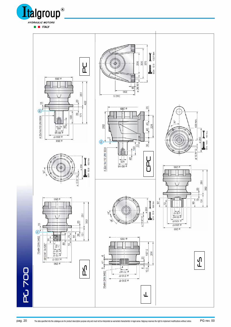
pag. 20 PG rev. 00The data specified into the catalogue are for product description purpose only and must not be interpreted as warranted characteristic in legal sense. Italgroup reserves the right to implement modifications without notice.
PG
70
0
PS
P
C
CP
C
FS
F
PG rev. 00 pag. 21The data specified into the catalogue are for product description purpose only and must not be interpreted as warranted characteristic in legal sense. Italgroup reserves the right to implement modifications without notice.
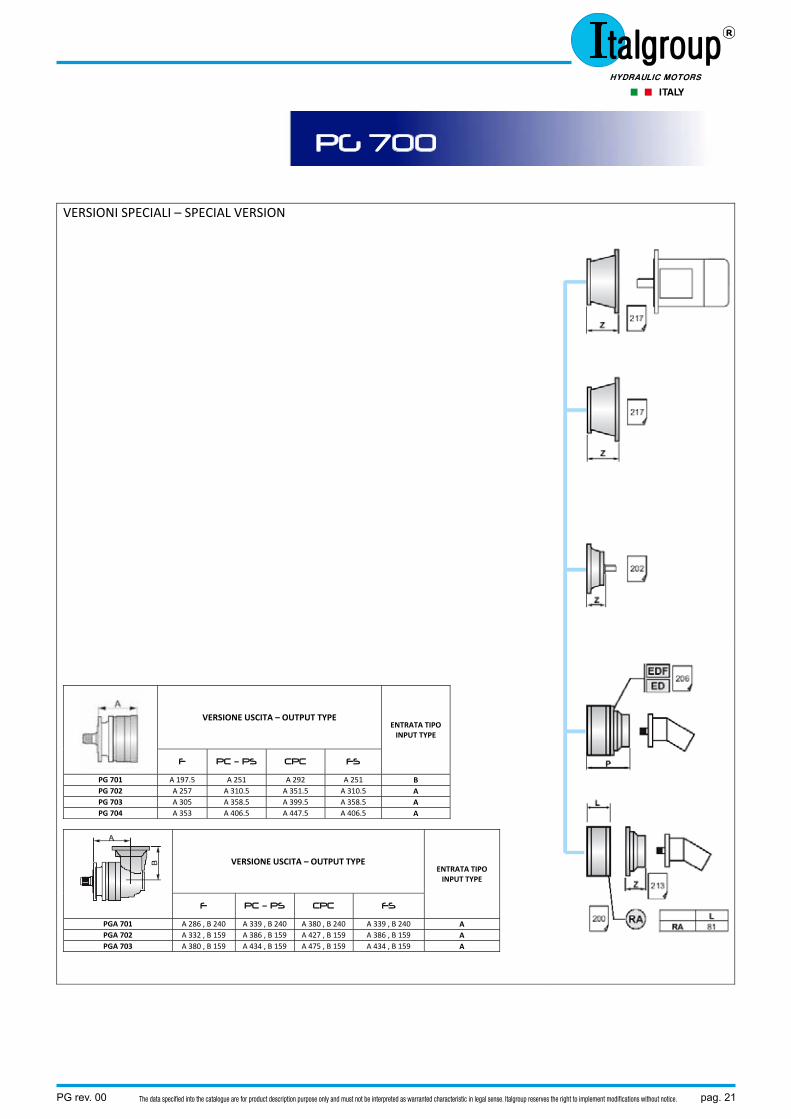
VERSIONI SPECIALI – SPECIAL VERSION
VERSIONE USCITA – OUTPUT TYPE ENTRATA TIPO INPUT TYPE
F PC – PS CPC FS
PG 701 A 197.5 A 251 A 292 A 251 B PG 702 A 257 A 310.5 A 351.5 A 310.5 A PG 703 A 305 A 358.5 A 399.5 A 358.5 A PG 704 A 353 A 406.5 A 447.5 A 406.5 A
VERSIONE USCITA – OUTPUT TYPE ENTRATA TIPO INPUT TYPE
F PC – PS CPC FS
PGA 701 A 286 , B 240 A 339 , B 240 A 380 , B 240 A 339 , B 240 A PGA 702 A 332 , B 159 A 386 , B 159 A 427 , B 159 A 386 , B 159 A PGA 703 A 380 , B 159 A 434 , B 159 A 475 , B 159 A 434 , B 159 A
PG 700
pag. 22 PG rev. 00The data specified into the catalogue are for product description purpose only and must not be interpreted as warranted characteristic in legal sense. Italgroup reserves the right to implement modifications without notice.
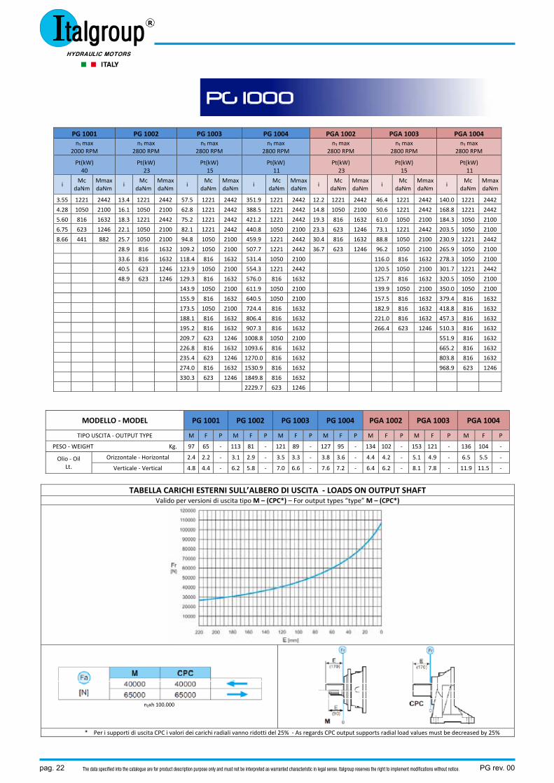
PG 1001 PG 1002 PG 1003 PG 1004 PGA 1002 PGA 1003 PGA 1004 n₁ max
2000 RPM n₁ max
2800 RPM n₁ max
2800 RPM n₁ max
2800 RPM n₁ max
2800 RPM n₁ max
2800 RPM n₁ max
2800 RPM
Pt(kW) 40
Pt(kW) 23
Pt(kW) 15
Pt(kW) 11
Pt(kW) 23
Pt(kW) 15
Pt(kW) 11
i Mc
daNm Mmax daNm
i Mc
daNm Mmax daNm
i Mc
daNm MmaxdaNm
i Mc
daNmMmaxdaNm
i Mc
daNmMmaxdaNm
i Mc
daNm Mmax daNm
i Mc
daNmMmaxdaNm
3.55 1221 2442 13.4 1221 2442 57.5 1221 2442 351.9 1221 2442 12.2 1221 2442 46.4 1221 2442 140.0 1221 2442
4.28 1050 2100 16.1 1050 2100 62.8 1221 2442 388.5 1221 2442 14.8 1050 2100 50.6 1221 2442 168.8 1221 2442
5.60 816 1632 18.3 1221 2442 75.2 1221 2442 421.2 1221 2442 19.3 816 1632 61.0 1050 2100 184.3 1050 2100
6.75 623 1246 22.1 1050 2100 82.1 1221 2442 440.8 1050 2100 23.3 623 1246 73.1 1221 2442 203.5 1050 2100
8.66 441 882 25.7 1050 2100 94.8 1050 2100 459.9 1221 2442 30.4 816 1632 88.8 1050 2100 230.9 1221 2442
28.9 816 1632 109.2 1050 2100 507.7 1221 2442 36.7 623 1246 96.2 1050 2100 265.9 1050 2100
33.6 816 1632 118.4 816 1632 531.4 1050 2100 116.0 816 1632 278.3 1050 2100
40.5 623 1246 123.9 1050 2100 554.3 1221 2442 120.5 1050 2100 301.7 1221 2442
48.9 623 1246 129.3 816 1632 576.0 816 1632 125.7 816 1632 320.5 1050 2100
143.9 1050 2100 611.9 1050 2100 139.9 1050 2100 350.0 1050 2100
155.9 816 1632 640.5 1050 2100 157.5 816 1632 379.4 816 1632
173.5 1050 2100 724.4 816 1632 182.9 816 1632 418.8 816 1632
188.1 816 1632 806.4 816 1632 221.0 816 1632 457.3 816 1632
195.2 816 1632 907.3 816 1632 266.4 623 1246 510.3 816 1632
209.7 623 1246 1008.8 1050 2100 551.9 816 1632
226.8 816 1632 1093.6 816 1632 665.2 816 1632
235.4 623 1246 1270.0 816 1632 803.8 816 1632
274.0 816 1632 1530.9 816 1632 968.9 623 1246
330.3 623 1246 1849.8 816 1632
2229.7 623 1246
MODELLO ‐ MODEL PG 1001 PG 1002 PG 1003 PG 1004 PGA 1002 PGA 1003 PGA 1004
TIPO USCITA ‐ OUTPUT TYPE M F P M F P M F P M F P M F P M F P M F P
PESO ‐ WEIGHT Kg. 97 65 ‐ 113 81 ‐ 121 89 ‐ 127 95 ‐ 134 102 ‐ 153 121 ‐ 136 104 ‐
Olio ‐ Oil Lt.
Orizzontale ‐ Horizontal 2.4 2.2 ‐ 3.1 2.9 ‐ 3.5 3.3 ‐ 3.8 3.6 ‐ 4.4 4.2 ‐ 5.1 4.9 ‐ 6.5 5.5 ‐
Verticale ‐ Vertical 4.8 4.4 ‐ 6.2 5.8 ‐ 7.0 6.6 ‐ 7.6 7.2 ‐ 6.4 6.2 ‐ 8.1 7.8 ‐ 11.9 11.5 ‐
TABELLA CARICHI ESTERNI SULL’ALBERO DI USCITA ‐ LOADS ON OUTPUT SHAFT Valido per versioni di uscita tipo M – (CPC*) – For output types “type” M – (CPC*)
n₂xh 100.000
* Per i supporti di uscita CPC i valori dei carichi radiali vanno ridotti del 25% ‐ As regards CPC output supports radial load values must be decreased by 25%
PG 1000
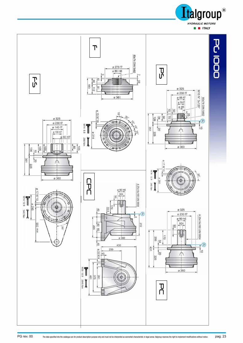
PG rev. 00 pag. 23The data specified into the catalogue are for product description purpose only and must not be interpreted as warranted characteristic in legal sense. Italgroup reserves the right to implement modifications without notice.
PG
100
0
PS
P
C
CP
C
FS
F
pag. 24 PG rev. 00The data specified into the catalogue are for product description purpose only and must not be interpreted as warranted characteristic in legal sense. Italgroup reserves the right to implement modifications without notice.
VERSIONI SPECIALI – SPECIAL VERSION
VERSIONE USCITA – OUTPUT TYPE ENTRATA TIPO INPUT TYPE
F MC – MS CPC FS
PG 1001 A 112 A 225 A 272 A 225 B PG 1002 A 184 A 297 A 344 A 297 A PG 1003 A 245 A 358 A 405 A 358 A PG 1004 A 293 A 406 A 453 A 406 A
VERSIONE USCITA – OUTPUT TYPE ENTRATA TIPO INPUT TYPE
F MC – MS CPC FS
PGA 1002 A 200 , B 240 A 313 , B 240 A 360 , B 240 A 313 , B 240 A PGA 1003 A 285 , B 240 A 398 , B 240 A 445 , B 240 A 398 , B 240 A PGA 1004 A 320 , B 159 A 433 , B 159 A 480 , B 159 A 433 , B 159 A
PG 1000
PG rev. 00 pag. 25The data specified into the catalogue are for product description purpose only and must not be interpreted as warranted characteristic in legal sense. Italgroup reserves the right to implement modifications without notice.
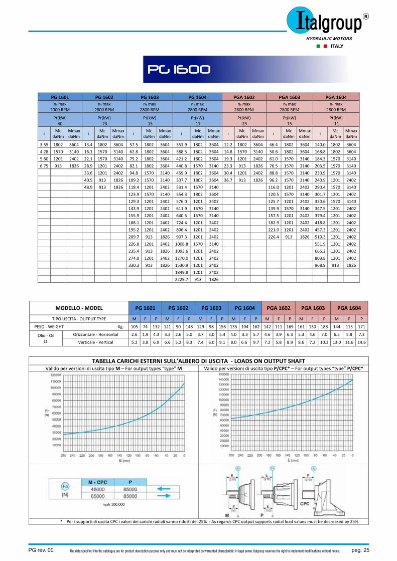
PG 1601 PG 1602 PG 1603 PG 1604 PGA 1602 PGA 1603 PGA 1604 n₁ max
2000 RPM n₁ max
2800 RPM n₁ max
2800 RPM n₁ max
2800 RPM n₁ max
2800 RPM n₁ max
2800 RPM n₁ max
2800 RPM
Pt(kW) 40
Pt(kW) 23
Pt(kW) 15
Pt(kW) 11
Pt(kW) 23
Pt(kW) 15
Pt(kW) 11
i Mc
daNm Mmax daNm
i Mc
daNm Mmax daNm
i Mc
daNm MmaxdaNm
i Mc
daNmMmaxdaNm
i Mc
daNmMmaxdaNm
i Mc
daNm Mmax daNm
i Mc
daNmMmaxdaNm
3.55 1802 3604 13.4 1802 3604 57.5 1802 3604 351.9 1802 3604 12.2 1802 3604 46.4 1802 3604 140.0 1802 3604
4.28 1570 3140 16.1 1570 3140 62.8 1802 3604 388.5 1802 3604 14.8 1570 3140 50.6 1802 3604 168.8 1802 3604
5.60 1201 2402 22.1 1570 3140 75.2 1802 3604 421.2 1802 3604 19.3 1201 2402 61.0 1570 3140 184.3 1570 3140
6.75 913 1826 28.9 1201 2402 82.1 1802 3604 440.8 1570 3140 23.3 913 1826 76.5 1570 3140 203.5 1570 3140
33.6 1201 2402 94.8 1570 3140 459.9 1802 3604 30.4 1201 2402 88.8 1570 3140 230.9 1570 3140
40.5 913 1826 109.2 1570 3140 507.7 1802 3604 36.7 913 1826 96.2 1570 3140 240.9 1201 2402
48.9 913 1826 118.4 1201 2402 531.4 1570 3140 116.0 1201 2402 290.4 1570 3140
123.9 1570 3140 554.3 1802 3604 120.5 1570 3140 301.7 1201 2402
129.3 1201 2402 576.0 1201 2402 125.7 1201 2402 320.6 1570 3140
143.9 1201 2402 611.9 1570 3140 139.9 1570 3140 347.5 1201 2402
155.9 1201 2402 640.5 1570 3140 157.5 1201 2402 379.4 1201 2402
188.1 1201 2402 724.4 1201 2402 182.9 1201 2402 418.8 1201 2402
195.2 1201 2402 806.4 1201 2402 221.0 1201 2402 457.3 1201 2402
209.7 913 1826 907.3 1201 2402 226.4 913 1826 510.3 1201 2402
226.8 1201 2402 1008.8 1570 3140 551.9 1201 2402
235.4 913 1826 1093.6 1201 2402 665.2 1201 2402
274.0 1201 2402 1270.0 1201 2402 803.8 1201 2402
330.3 913 1826 1530.9 1201 2402 968.9 913 1826
1849.8 1201 2402
2229.7 913 1826
MODELLO ‐ MODEL PG 1601 PG 1602 PG 1603 PG 1604 PGA 1602 PGA 1603 PGA 1604
TIPO USCITA ‐ OUTPUT TYPE M F P M F P M F P M F P M F P M F P M F P
PESO ‐ WEIGHT Kg. 105 74 132 121 90 148 129 98 156 135 104 162 142 111 169 161 130 188 144 113 171
Olio ‐ Oil Lt.
Orizzontale ‐ Horizontal 2.6 1.9 4.3 3.3 2.6 5.0 3.7 3.0 5.4 4.0 3.3 5.7 4.6 3.9 6.3 5.3 4.6 7.0 6.5 5.8 7.3
Verticale ‐ Vertical 5.2 3.8 6.9 6.6 5.2 8.3 7.4 6.0 9.1 8.0 6.6 9.7 7.2 5.8 8.9 8.6 7.2 10.3 13.0 11.6 14.6
TABELLA CARICHI ESTERNI SULL’ALBERO DI USCITA ‐ LOADS ON OUTPUT SHAFT Valido per versioni di uscita tipo M – For output types “type” M Valido per versioni di uscita tipo P/CPC* – For output types “type” P/CPC*
n₂xh 100.000
* Per i supporti di uscita CPC i valori dei carichi radiali vanno ridotti del 25% ‐ As regards CPC output supports radial load values must be decreased by 25%
PG 1600
pag. 26 PG rev. 00The data specified into the catalogue are for product description purpose only and must not be interpreted as warranted characteristic in legal sense. Italgroup reserves the right to implement modifications without notice.
PG
160
0
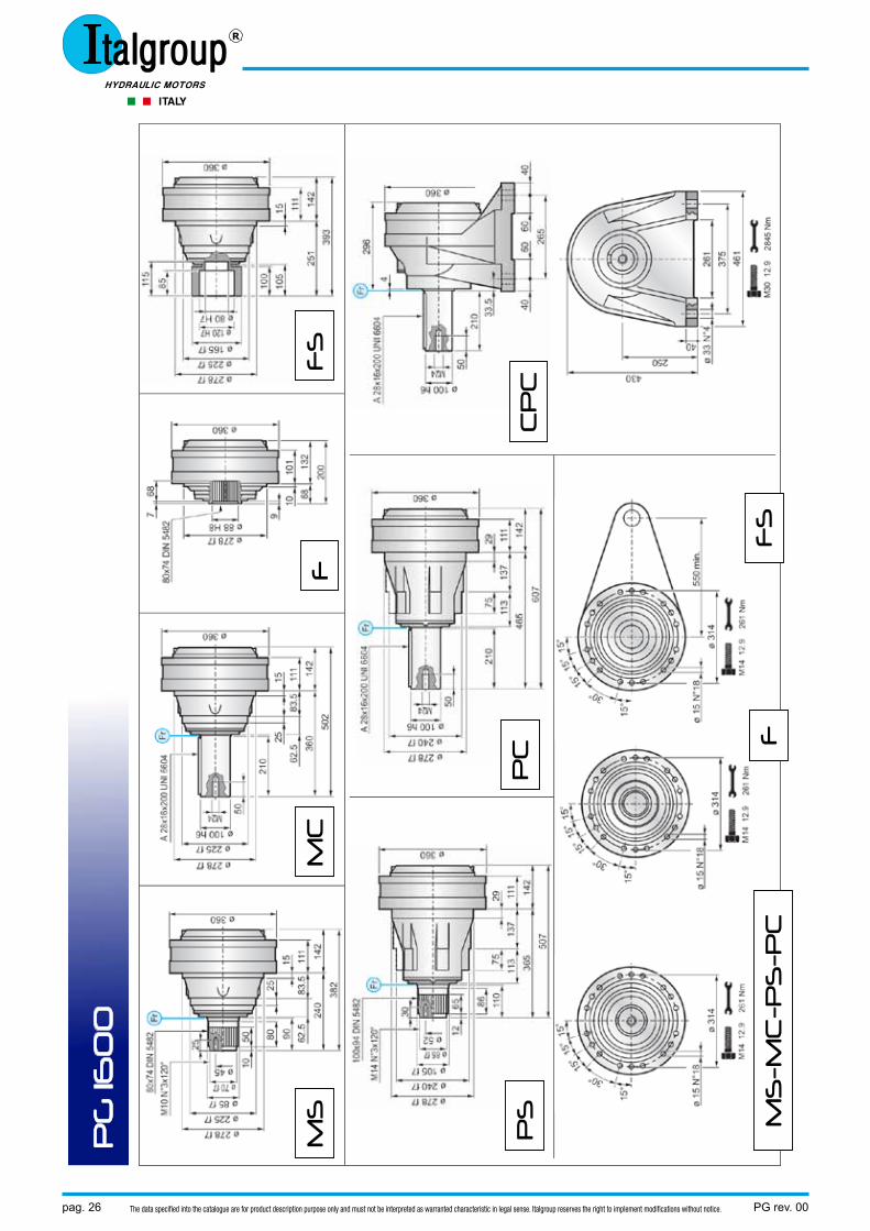
MS
M
C
F
FS
PS
P
C
CP
C
MS
-MC
-PS
-PC
F
S
F
PG rev. 00 pag. 27The data specified into the catalogue are for product description purpose only and must not be interpreted as warranted characteristic in legal sense. Italgroup reserves the right to implement modifications without notice.
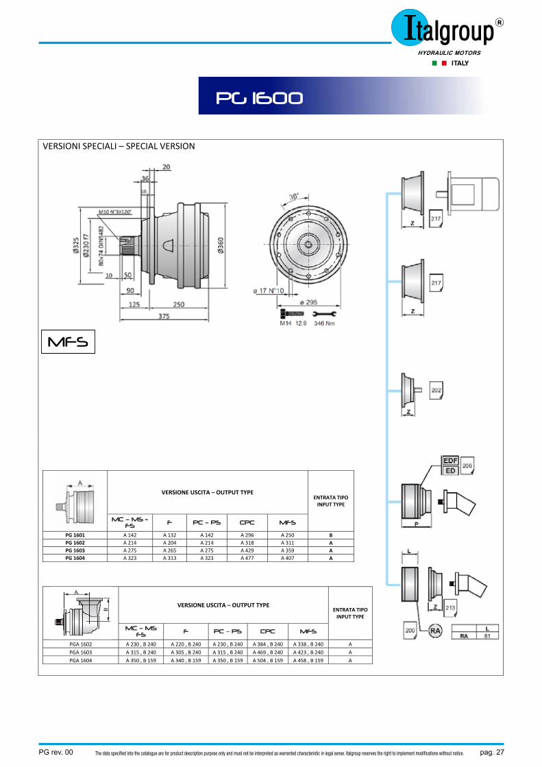
VERSIONI SPECIALI – SPECIAL VERSION
VERSIONE USCITA – OUTPUT TYPE ENTRATA TIPO INPUT TYPE
MC – MS - FS F PC – PS CPC MFS
PG 1601 A 142 A 132 A 142 A 296 A 250 B PG 1602 A 214 A 204 A 214 A 318 A 311 A PG 1603 A 275 A 265 A 275 A 429 A 359 A PG 1604 A 323 A 313 A 323 A 477 A 407 A
VERSIONE USCITA – OUTPUT TYPE ENTRATA TIPO INPUT TYPE
MC – MS FS F PC – PS CPC MFS
PGA 1602 A 230 , B 240 A 220 , B 240 A 230 , B 240 A 384 , B 240 A 338 , B 240 A PGA 1603 A 315 , B 240 A 305 , B 240 A 315 , B 240 A 469 , B 240 A 423 , B 240 A PGA 1604 A 350 , B 159 A 340 , B 159 A 350 , B 159 A 504 , B 159 A 458 , B 159 A
PG 1600
MFS
pag. 28 PG rev. 00The data specified into the catalogue are for product description purpose only and must not be interpreted as warranted characteristic in legal sense. Italgroup reserves the right to implement modifications without notice.
PG 1802 PG 1803 PG 1804 PGA 1802 PGA 1803 PGA 1804 n₁ max
2800 RPM n₁ max
2800 RPM n₁ max
2800 RPM n₁ max
2000 RPM n₁ max
2800 RPM n₁ max
2800 RPM
Pt(kW) 25
Pt(kW) 17
Pt(kW) 13
Pt(kW) 25
Pt(kW) 17
Pt(kW) 13
i Mc
daNm Mmax daNm
i Mc
daNm Mmax daNm
i Mc
daNm MmaxdaNm
i Mc
daNm MmaxdaNm
i Mc
daNm Mmax daNm
i Mc
daNm MmaxdaNm
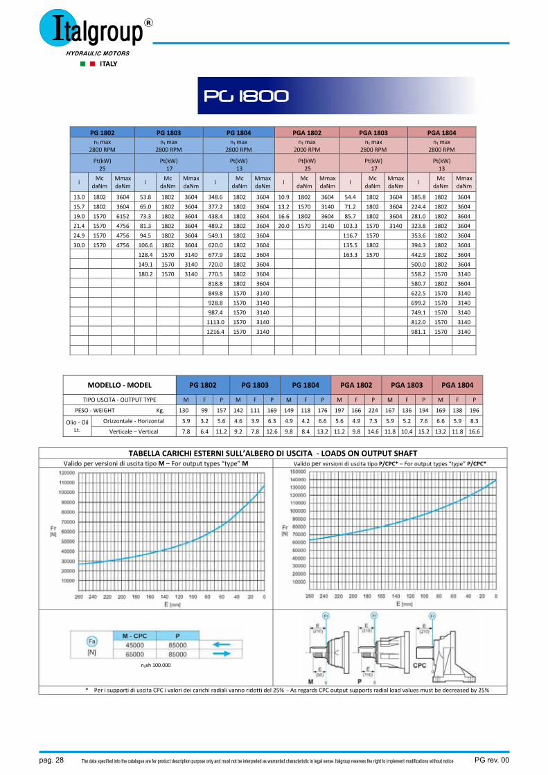
13.0 1802 3604 53.8 1802 3604 348.6 1802 3604 10.9 1802 3604 54.4 1802 3604 185.8 1802 3604
15.7 1802 3604 65.0 1802 3604 377.2 1802 3604 13.2 1570 3140 71.2 1802 3604 224.4 1802 3604
19.0 1570 6152 73.3 1802 3604 438.4 1802 3604 16.6 1802 3604 85.7 1802 3604 281.0 1802 3604
21.4 1570 4756 81.3 1802 3604 489.2 1802 3604 20.0 1570 3140 103.3 1570 3140 323.8 1802 3604
24.9 1570 4756 94.5 1802 3604 549.1 1802 3604 116.7 1570 353.6 1802 3604
30.0 1570 4756 106.6 1802 3604 620.0 1802 3604 135.5 1802 394.3 1802 3604
128.4 1570 3140 677.9 1802 3604 163.3 1570 442.9 1802 3604
149.1 1570 3140 720.0 1802 3604 500.0 1802 3604
180.2 1570 3140 770.5 1802 3604 558.2 1570 3140
818.8 1802 3604 580.7 1802 3604
849.8 1570 3140 622.5 1570 3140
928.8 1570 3140 699.2 1570 3140
987.4 1570 3140 749.1 1570 3140
1113.0 1570 3140 812.0 1570 3140
1216.4 1570 3140 981.1 1570 3140
MODELLO ‐ MODEL PG 1802 PG 1803 PG 1804 PGA 1802 PGA 1803 PGA 1804
TIPO USCITA ‐ OUTPUT TYPE M F P M F P M F P M F P M F P M F P
PESO ‐ WEIGHT Kg. 130 99 157 142 111 169 149 118 176 197 166 224 167 136 194 169 138 196
Olio ‐ Oil Lt.
Orizzontale ‐ Horizontal 3.9 3.2 5.6 4.6 3.9 6.3 4.9 4.2 6.6 5.6 4.9 7.3 5.9 5.2 7.6 6.6 5.9 8.3
Verticale – Vertical 7.8 6.4 11.2 9.2 7.8 12.6 9.8 8.4 13.2 11.2 9.8 14.6 11.8 10.4 15.2 13.2 11.8 16.6
TABELLA CARICHI ESTERNI SULL’ALBERO DI USCITA ‐ LOADS ON OUTPUT SHAFT Valido per versioni di uscita tipo M – For output types “type” M Valido per versioni di uscita tipo P/CPC* – For output types “type” P/CPC*
n₂xh 100.000
* Per i supporti di uscita CPC i valori dei carichi radiali vanno ridotti del 25% ‐ As regards CPC output supports radial load values must be decreased by 25%
PG 1800
PG rev. 00 pag. 29The data specified into the catalogue are for product description purpose only and must not be interpreted as warranted characteristic in legal sense. Italgroup reserves the right to implement modifications without notice.
PG
180
0
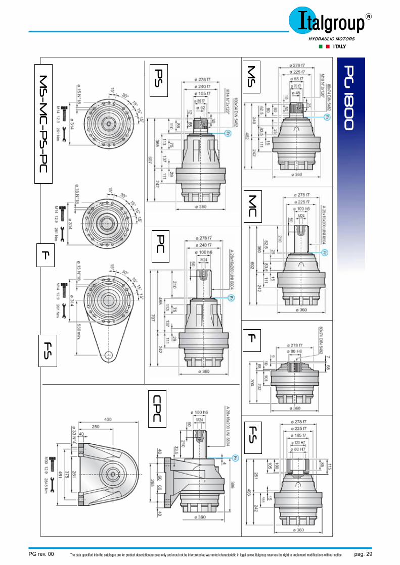
MS
M
C
F
FS
PS
P
C
CP
C
MS
-MC
-PS
-PC
F
S
F
pag. 30 PG rev. 00The data specified into the catalogue are for product description purpose only and must not be interpreted as warranted characteristic in legal sense. Italgroup reserves the right to implement modifications without notice.
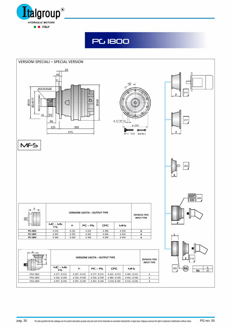
VERSIONI SPECIALI – SPECIAL VERSION
VERSIONE USCITA – OUTPUT TYPE ENTRATA TIPO INPUT TYPE
MC – MS FS F PC – PS CPC MFS
PG 1802 A 242 A 232 A 242 A 396 A 350 B PG 1803 A 302 A 292 A 302 A 456 A 410 A PG 1804 A 346 A 336 A 346 A 504 A 454 A
VERSIONE USCITA – OUTPUT TYPE ENTRATA TIPO INPUT TYPE
MC – MS FS F PC – PS CPC MFS
PGA 1802 A 277 , B 315 A 267 , B 315 A 277 , B 315 A 431 , B 315 A 385 , B 315 A PGA 1803 A 334 , B 240 A 324 , B 240 A 334 , B 240 A 484 , B 240 A 442 , B 240 A PGA 1804 A 407 , B 240 A 397 , B 240 A 407 , B 240 A 544, B 240 A 515 , B 240 A
PG 1800
MFS
PG rev. 00 pag. 31The data specified into the catalogue are for product description purpose only and must not be interpreted as warranted characteristic in legal sense. Italgroup reserves the right to implement modifications without notice.
PG 2501 PG 2502 PG 2503 PG 2504 PGA 2502 PGA 2503 PGA 2504 n₁ max
1500 RPM n₁ max
2800 RPM n₁ max
2800 RPM n₁ max
2800 RPM n₁ max
2000 RPM n₁ max
2800 RPM n₁ max
2800 RPM
Pt(kW) 50
Pt(kW) 30
Pt(kW) 20
Pt(kW) 15
Pt(kW) 30
Pt(kW) 20
Pt(kW) 15
i Mc
daNm Mmax daNm
i Mc
daNm Mmax daNm
i Mc
daNm MmaxdaNm
i Mc
daNmMmaxdaNm
i Mc
daNmMmaxdaNm
i Mc
daNm Mmax daNm
i Mc
daNmMmaxdaNm
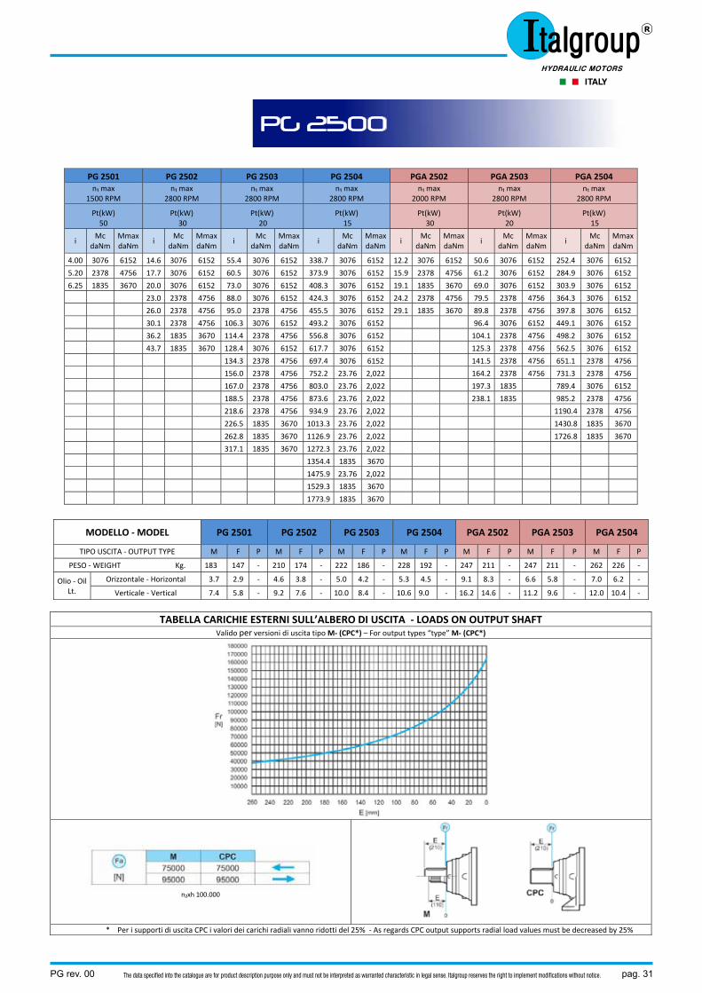
4.00 3076 6152 14.6 3076 6152 55.4 3076 6152 338.7 3076 6152 12.2 3076 6152 50.6 3076 6152 252.4 3076 6152
5.20 2378 4756 17.7 3076 6152 60.5 3076 6152 373.9 3076 6152 15.9 2378 4756 61.2 3076 6152 284.9 3076 6152
6.25 1835 3670 20.0 3076 6152 73.0 3076 6152 408.3 3076 6152 19.1 1835 3670 69.0 3076 6152 303.9 3076 6152
23.0 2378 4756 88.0 3076 6152 424.3 3076 6152 24.2 2378 4756 79.5 2378 4756 364.3 3076 6152
26.0 2378 4756 95.0 2378 4756 455.5 3076 6152 29.1 1835 3670 89.8 2378 4756 397.8 3076 6152
30.1 2378 4756 106.3 3076 6152 493.2 3076 6152 96.4 3076 6152 449.1 3076 6152
36.2 1835 3670 114.4 2378 4756 556.8 3076 6152 104.1 2378 4756 498.2 3076 6152
43.7 1835 3670 128.4 3076 6152 617.7 3076 6152 125.3 2378 4756 562.5 3076 6152
134.3 2378 4756 697.4 3076 6152 141.5 2378 4756 651.1 2378 4756
156.0 2378 4756 752.2 23.76 2,022 164.2 2378 4756 731.3 2378 4756
167.0 2378 4756 803.0 23.76 2,022 197.3 1835 789.4 3076 6152
188.5 2378 4756 873.6 23.76 2,022 238.1 1835 985.2 2378 4756
218.6 2378 4756 934.9 23.76 2,022 1190.4 2378 4756
226.5 1835 3670 1013.3 23.76 2,022 1430.8 1835 3670
262.8 1835 3670 1126.9 23.76 2,022 1726.8 1835 3670
317.1 1835 3670 1272.3 23.76 2,022
1354.4 1835 3670
1475.9 23.76 2,022
1529.3 1835 3670
1773.9 1835 3670
MODELLO ‐ MODEL PG 2501 PG 2502 PG 2503 PG 2504 PGA 2502 PGA 2503 PGA 2504
TIPO USCITA ‐ OUTPUT TYPE M F P M F P M F P M F P M F P M F P M F P
PESO ‐ WEIGHT Kg. 183 147 ‐ 210 174 ‐ 222 186 ‐ 228 192 ‐ 247 211 ‐ 247 211 ‐ 262 226 ‐
Olio ‐ Oil Lt.
Orizzontale ‐ Horizontal 3.7 2.9 ‐ 4.6 3.8 ‐ 5.0 4.2 ‐ 5.3 4.5 ‐ 9.1 8.3 ‐ 6.6 5.8 ‐ 7.0 6.2 ‐
Verticale ‐ Vertical 7.4 5.8 ‐ 9.2 7.6 ‐ 10.0 8.4 ‐ 10.6 9.0 ‐ 16.2 14.6 ‐ 11.2 9.6 ‐ 12.0 10.4 ‐
TABELLA CARICHIE ESTERNI SULL’ALBERO DI USCITA ‐ LOADS ON OUTPUT SHAFT Valido per versioni di uscita tipo M‐ (CPC*) – For output types “type” M‐ (CPC*)
n₂xh 100.000
* Per i supporti di uscita CPC i valori dei carichi radiali vanno ridotti del 25% ‐ As regards CPC output supports radial load values must be decreased by 25%
PG 2500

pag. 32 PG rev. 00The data specified into the catalogue are for product description purpose only and must not be interpreted as warranted characteristic in legal sense. Italgroup reserves the right to implement modifications without notice.
PG
25
00
MS
M
C
CP
C
FS
F

PG rev. 00 pag. 33The data specified into the catalogue are for product description purpose only and must not be interpreted as warranted characteristic in legal sense. Italgroup reserves the right to implement modifications without notice.
VERSIONI SPECIALI – SPECIAL VERSION
VERSIONE USCITA – OUTPUT TYPE ENTRATA TIPO INPUT TYPE
F PC – PS CPC FS
PG 701 A 197.5 A 251 A 292 A 251 B PG 702 A 257 A 310.5 A 351.5 A 310.5 A PG 703 A 305 A 358.5 A 399.5 A 358.5 A PG 704 A 353 A 406.5 A 447.5 A 406.5 A
VERSIONE USCITA – OUTPUT TYPE ENTRATA TIPO INPUT TYPE
F PC – PS CPC FS
PGA 701 A 286 , B 240 A 339 , B 240 A 380 , B 240 A 339 , B 240 A PGA 702 A 332 , B 159 A 386 , B 159 A 427 , B 159 A 386 , B 159 A PGA 703 A 380 , B 159 A 434 , B 159 A 475 , B 159 A 434 , B 159 A
PG 2500
pag. 34 PG rev. 00The data specified into the catalogue are for product description purpose only and must not be interpreted as warranted characteristic in legal sense. Italgroup reserves the right to implement modifications without notice.
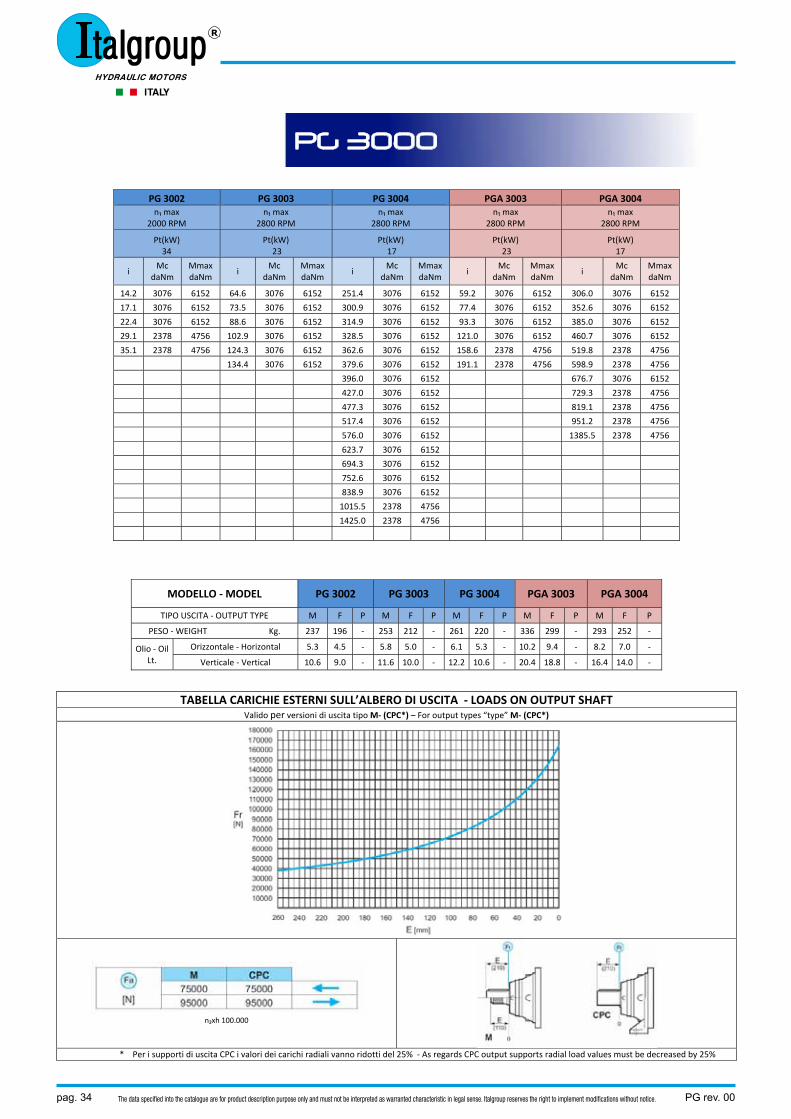
PG 3002 PG 3003 PG 3004 PGA 3003 PGA 3004 n₁ max
2000 RPM n₁ max
2800 RPM n₁ max
2800 RPM n₁ max
2800 RPM n₁ max
2800 RPM
Pt(kW) 34
Pt(kW) 23
Pt(kW) 17
Pt(kW) 23
Pt(kW) 17
i Mc
daNm Mmax daNm
i Mc
daNm Mmax daNm
i Mc
daNm MmaxdaNm
i Mc
daNm Mmax daNm
i Mc
daNm MmaxdaNm
14.2 3076 6152 64.6 3076 6152 251.4 3076 6152 59.2 3076 6152 306.0 3076 6152
17.1 3076 6152 73.5 3076 6152 300.9 3076 6152 77.4 3076 6152 352.6 3076 6152
22.4 3076 6152 88.6 3076 6152 314.9 3076 6152 93.3 3076 6152 385.0 3076 6152
29.1 2378 4756 102.9 3076 6152 328.5 3076 6152 121.0 3076 6152 460.7 3076 6152
35.1 2378 4756 124.3 3076 6152 362.6 3076 6152 158.6 2378 4756 519.8 2378 4756
134.4 3076 6152 379.6 3076 6152 191.1 2378 4756 598.9 2378 4756
396.0 3076 6152 676.7 3076 6152
427.0 3076 6152 729.3 2378 4756
477.3 3076 6152 819.1 2378 4756
517.4 3076 6152 951.2 2378 4756
576.0 3076 6152 1385.5 2378 4756
623.7 3076 6152
694.3 3076 6152
752.6 3076 6152
838.9 3076 6152
1015.5 2378 4756
1425.0 2378 4756
MODELLO ‐ MODEL PG 3002 PG 3003 PG 3004 PGA 3003 PGA 3004
TIPO USCITA ‐ OUTPUT TYPE M F P M F P M F P M F P M F P
PESO ‐ WEIGHT Kg. 237 196 ‐ 253 212 ‐ 261 220 ‐ 336 299 ‐ 293 252 ‐
Olio ‐ Oil Lt.
Orizzontale ‐ Horizontal 5.3 4.5 ‐ 5.8 5.0 ‐ 6.1 5.3 ‐ 10.2 9.4 ‐ 8.2 7.0 ‐
Verticale ‐ Vertical 10.6 9.0 ‐ 11.6 10.0 ‐ 12.2 10.6 ‐ 20.4 18.8 ‐ 16.4 14.0 ‐
TABELLA CARICHIE ESTERNI SULL’ALBERO DI USCITA ‐ LOADS ON OUTPUT SHAFT Valido per versioni di uscita tipo M‐ (CPC*) – For output types “type” M‐ (CPC*)
n₂xh 100.000
* Per i supporti di uscita CPC i valori dei carichi radiali vanno ridotti del 25% ‐ As regards CPC output supports radial load values must be decreased by 25%
PG 3000
PG rev. 00 pag. 35The data specified into the catalogue are for product description purpose only and must not be interpreted as warranted characteristic in legal sense. Italgroup reserves the right to implement modifications without notice.
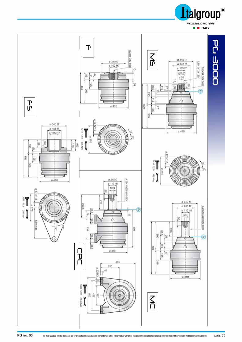
PG
30
00
MS
M
C
CP
C
FS
F
pag. 36 PG rev. 00The data specified into the catalogue are for product description purpose only and must not be interpreted as warranted characteristic in legal sense. Italgroup reserves the right to implement modifications without notice.
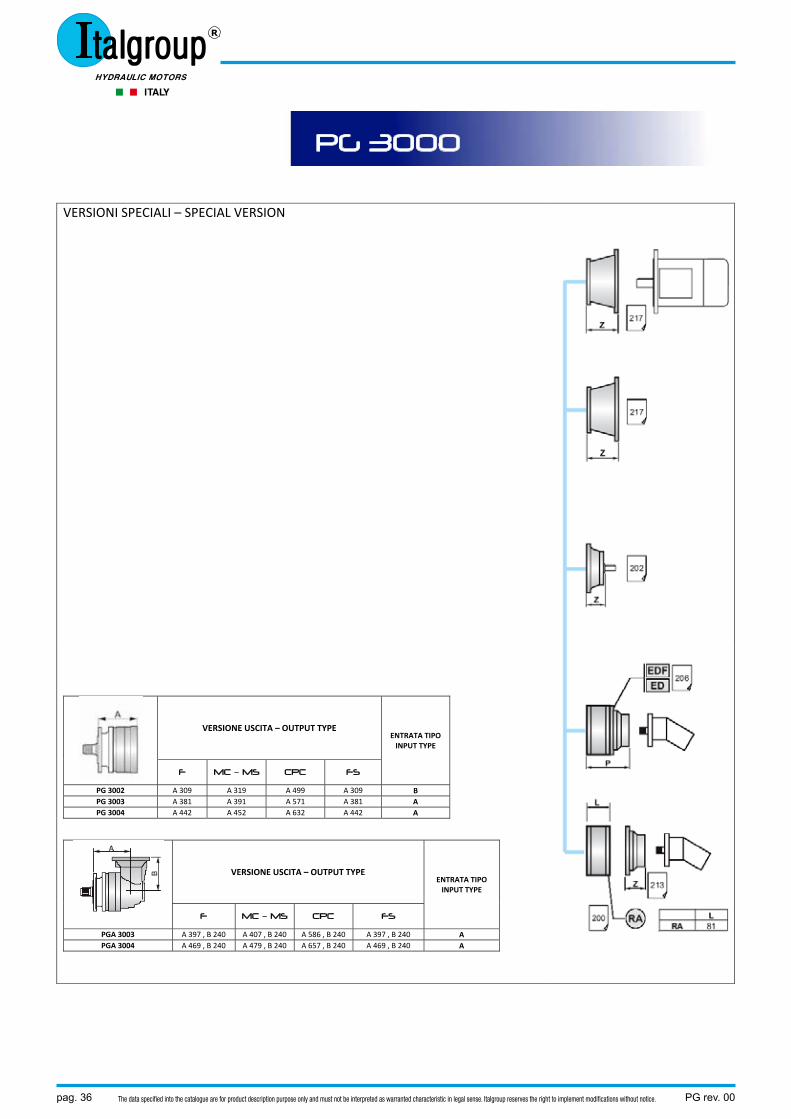
VERSIONI SPECIALI – SPECIAL VERSION
VERSIONE USCITA – OUTPUT TYPE ENTRATA TIPO INPUT TYPE
F MC – MS CPC FS
PG 3002 A 309 A 319 A 499 A 309 B PG 3003 A 381 A 391 A 571 A 381 A PG 3004 A 442 A 452 A 632 A 442 A
VERSIONE USCITA – OUTPUT TYPE ENTRATA TIPO INPUT TYPE
F MC – MS CPC FS
PGA 3003 A 397 , B 240 A 407 , B 240 A 586 , B 240 A 397 , B 240 A PGA 3004 A 469 , B 240 A 479 , B 240 A 657 , B 240 A 469 , B 240 A
PG 3000
PG rev. 00 pag. 37The data specified into the catalogue are for product description purpose only and must not be interpreted as warranted characteristic in legal sense. Italgroup reserves the right to implement modifications without notice.
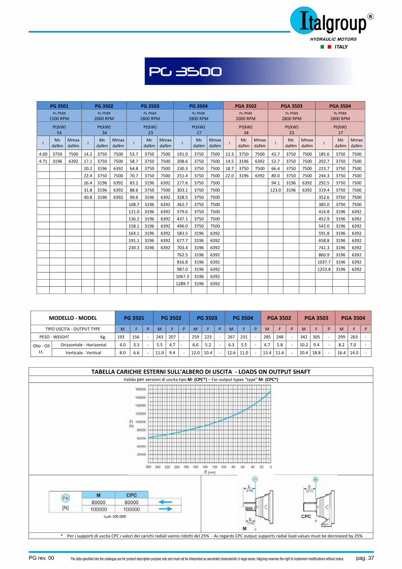
PG 3501 PG 3502 PG 3503 PG 3504 PGA 3502 PGA 3503 PGA 3504 n₁ max
1500 RPM n₁ max
2000 RPM n₁ max
2800 RPM n₁ max
2800 RPM n₁ max
2000 RPM n₁ max
2800 RPM n₁ max
2800 RPM
Pt(kW) 54
Pt(kW) 34
Pt(kW) 23
Pt(kW) 17
Pt(kW) 34
Pt(kW) 23
Pt(kW) 17
i Mc
daNm Mmax daNm
i Mc
daNm Mmax daNm
i Mc
daNm MmaxdaNm
i Mc
daNmMmaxdaNm
i Mc
daNmMmaxdaNm
i Mc
daNm Mmax daNm
i Mc
daNmMmaxdaNm
4.00 3750 7500 14.2 3750 7500 53.7 3750 7500 191.0 3750 7500 12.3 3750 7500 43.7 3750 7500 185.6 3750 7500
4.71 3196 6392 17.1 3750 7500 58.7 3750 7500 208.6 3750 7500 14.5 3196 6392 52.7 3750 7500 202.7 3750 7500
20.2 3196 6392 64.8 3750 7500 230.3 3750 7500 18.7 3750 7500 66.4 3750 7500 223.7 3750 7500
22.4 3750 7500 70.7 3750 7500 251.4 3750 7500 22.0 3196 6392 80.0 3750 7500 244.3 3750 7500
26.4 3196 6392 83.2 3196 6392 277.6 3750 7500 94.1 3196 6392 292.5 3750 7500
31.8 3196 6392 88.6 3750 7500 303.1 3750 7500 123.0 3196 6392 319.4 3750 7500
40.8 3196 6392 99.6 3196 6392 328.5 3750 7500 352.6 3750 7500
108.7 3196 6392 362.7 3750 7500 385.0 3750 7500
121.0 3196 6392 379.6 3750 7500 414.8 3196 6392
136.2 3196 6392 437.1 3750 7500 452.9 3196 6392
158.1 3196 6392 496.0 3750 7500 542.0 3196 6392
164.1 3196 6392 583.5 3196 6392 591.8 3196 6392
191.1 3196 6392 677.7 3196 6392 658.8 3196 6392
230.3 3196 6392 703.4 3196 6392 741.3 3196 6392
762.5 3196 6392 860.9 3196 6392
816.8 3196 6392 1037.7 3196 6392
987.0 3196 6392 1253.8 3196 6392
1067.3 3196 6392
1289.7 3196 6392
MODELLO ‐ MODEL PG 3501 PG 3502 PG 3503 PG 3504 PGA 3502 PGA 3503 PGA 3504
TIPO USCITA ‐ OUTPUT TYPE M F P M F P M F P M F P M F P M F P M F P
PESO ‐ WEIGHT Kg. 193 156 ‐ 243 207 ‐ 259 223 ‐ 267 231 ‐ 285 248 ‐ 342 305 ‐ 299 263 ‐
Olio ‐ Oil Lt.
Orizzontale ‐ Horizontal 4.0 3.3 ‐ 5.5 4.7 ‐ 6.0 5.2 ‐ 6.3 5.5 ‐ 6.7 5.8 ‐ 10.2 9.4 ‐ 8.2 7.0 ‐
Verticale ‐ Vertical 8.0 6.6 ‐ 11.0 9.4 ‐ 12.0 10.4 ‐ 12.6 11.0 ‐ 13.4 11.6 ‐ 20.4 18.8 ‐ 16.4 14.0 ‐
TABELLA CARICHIE ESTERNI SULL’ALBERO DI USCITA ‐ LOADS ON OUTPUT SHAFT Valido per versioni di uscita tipo M‐ (CPC*) – For output types “type” M‐ (CPC*)
n₂xh 100.000
* Per i supporti di uscita CPC i valori dei carichi radiali vanno ridotti del 25% ‐ As regards CPC output supports radial load values must be decreased by 25%
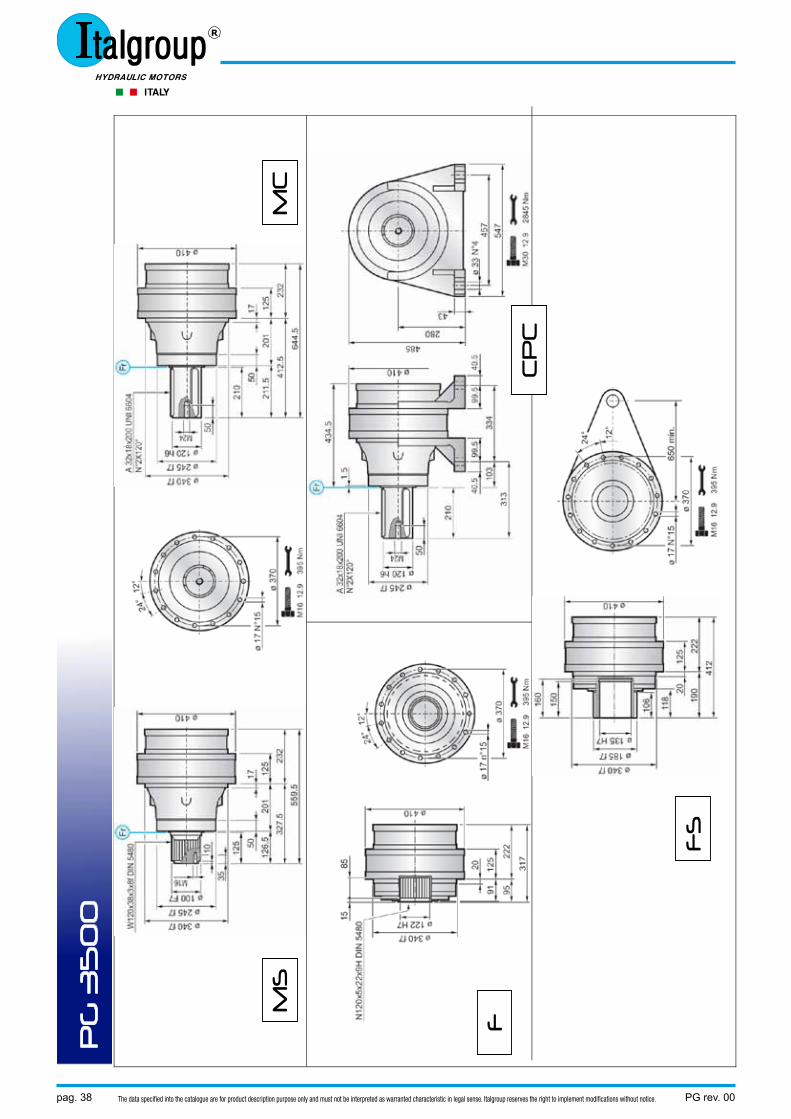
PG 3500
pag. 38 PG rev. 00The data specified into the catalogue are for product description purpose only and must not be interpreted as warranted characteristic in legal sense. Italgroup reserves the right to implement modifications without notice.
PG
35
00
MS
M
C
CP
C
FS
F
PG rev. 00 pag. 39The data specified into the catalogue are for product description purpose only and must not be interpreted as warranted characteristic in legal sense. Italgroup reserves the right to implement modifications without notice.
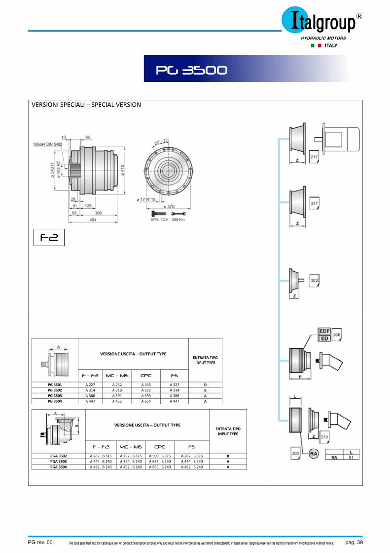
VERSIONI SPECIALI – SPECIAL VERSION
VERSIONE USCITA – OUTPUT TYPE ENTRATA TIPO INPUT TYPE
F – F2 MC – MS CPC FS
PG 3501 A 227 A 232 A 435 A 227 D PG 3502 A 314 A 319 A 522 A 314 B PG 3503 A 386 A 391 A 593 A 386 A PG 3504 A 447 A 452 A 654 A 447 A
VERSIONE USCITA – OUTPUT TYPE ENTRATA TIPO INPUT TYPE
F – F2 MC – MS CPC FS
PGA 3502 A 287 , B 315 A 297 , B 315 A 500 , B 315 A 287 , B 315 B PGA 3503 A 444 , B 240 A 454 , B 240 A 657 , B 240 A 444 , B 240 A PGA 3504 A 482 , B 240 A 492 , B 240 A 695 , B 240 A 482 , B 240 A
PG 3500
F2
pag. 40 PG rev. 00The data specified into the catalogue are for product description purpose only and must not be interpreted as warranted characteristic in legal sense. Italgroup reserves the right to implement modifications without notice.
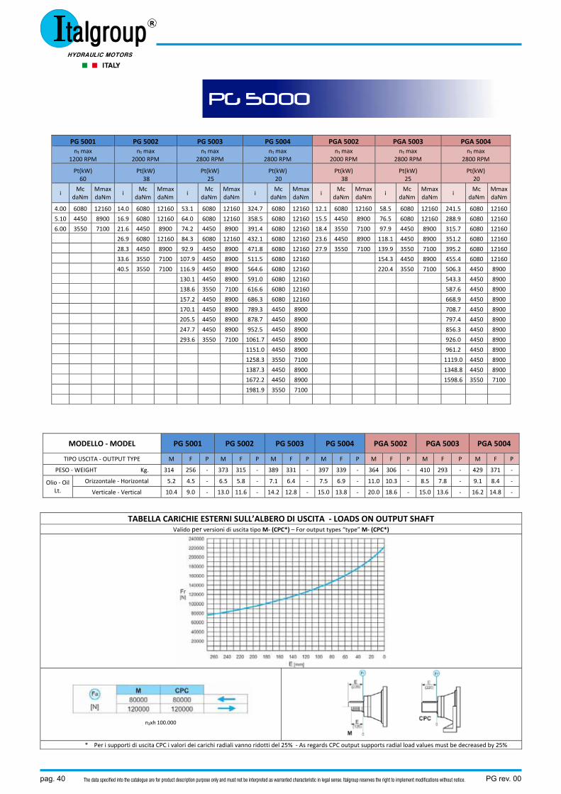
PG 5001 PG 5002 PG 5003 PG 5004 PGA 5002 PGA 5003 PGA 5004 n₁ max
1200 RPM n₁ max
2000 RPM n₁ max
2800 RPM n₁ max
2800 RPM n₁ max
2000 RPM n₁ max
2800 RPM n₁ max
2800 RPM
Pt(kW) 60
Pt(kW) 38
Pt(kW) 25
Pt(kW) 20
Pt(kW) 38
Pt(kW) 25
Pt(kW) 20
i Mc
daNm Mmax daNm
i Mc
daNm Mmax daNm
i Mc
daNm MmaxdaNm
i Mc
daNmMmaxdaNm
i Mc
daNmMmaxdaNm
i Mc
daNm Mmax daNm
i Mc
daNmMmaxdaNm
4.00 6080 12160 14.0 6080 12160 53.1 6080 12160 324.7 6080 12160 12.1 6080 12160 58.5 6080 12160 241.5 6080 12160
5.10 4450 8900 16.9 6080 12160 64.0 6080 12160 358.5 6080 12160 15.5 4450 8900 76.5 6080 12160 288.9 6080 12160
6.00 3550 7100 21.6 4450 8900 74.2 4450 8900 391.4 6080 12160 18.4 3550 7100 97.9 4450 8900 315.7 6080 12160
26.9 6080 12160 84.3 6080 12160 432.1 6080 12160 23.6 4450 8900 118.1 4450 8900 351.2 6080 12160
28.3 4450 8900 92.9 4450 8900 471.8 6080 12160 27.9 3550 7100 139.9 3550 7100 395.2 6080 12160
33.6 3550 7100 107.9 4450 8900 511.5 6080 12160 154.3 4450 8900 455.4 6080 12160
40.5 3550 7100 116.9 4450 8900 564.6 6080 12160 220.4 3550 7100 506.3 4450 8900
130.1 4450 8900 591.0 6080 12160 543.3 4450 8900
138.6 3550 7100 616.6 6080 12160 587.6 4450 8900
157.2 4450 8900 686.3 6080 12160 668.9 4450 8900
170.1 4450 8900 789.3 4450 8900 708.7 4450 8900
205.5 4450 8900 878.7 4450 8900 797.4 4450 8900
247.7 4450 8900 952.5 4450 8900 856.3 4450 8900
293.6 3550 7100 1061.7 4450 8900 926.0 4450 8900
1151.0 4450 8900 961.2 4450 8900
1258.3 3550 7100 1119.0 4450 8900
1387.3 4450 8900 1348.8 4450 8900
1672.2 4450 8900 1598.6 3550 7100
1981.9 3550 7100
MODELLO ‐ MODEL PG 5001 PG 5002 PG 5003 PG 5004 PGA 5002 PGA 5003 PGA 5004
TIPO USCITA ‐ OUTPUT TYPE M F P M F P M F P M F P M F P M F P M F P
PESO ‐ WEIGHT Kg. 314 256 ‐ 373 315 ‐ 389 331 ‐ 397 339 ‐ 364 306 ‐ 410 293 ‐ 429 371 ‐
Olio ‐ Oil Lt.
Orizzontale ‐ Horizontal 5.2 4.5 ‐ 6.5 5.8 ‐ 7.1 6.4 ‐ 7.5 6.9 ‐ 11.0 10.3 ‐ 8.5 7.8 ‐ 9.1 8.4 ‐
Verticale ‐ Vertical 10.4 9.0 ‐ 13.0 11.6 ‐ 14.2 12.8 ‐ 15.0 13.8 ‐ 20.0 18.6 ‐ 15.0 13.6 ‐ 16.2 14.8 ‐
TABELLA CARICHIE ESTERNI SULL’ALBERO DI USCITA ‐ LOADS ON OUTPUT SHAFT Valido per versioni di uscita tipo M‐ (CPC*) – For output types “type” M‐ (CPC*)
n₂xh 100.000
* Per i supporti di uscita CPC i valori dei carichi radiali vanno ridotti del 25% ‐ As regards CPC output supports radial load values must be decreased by 25%
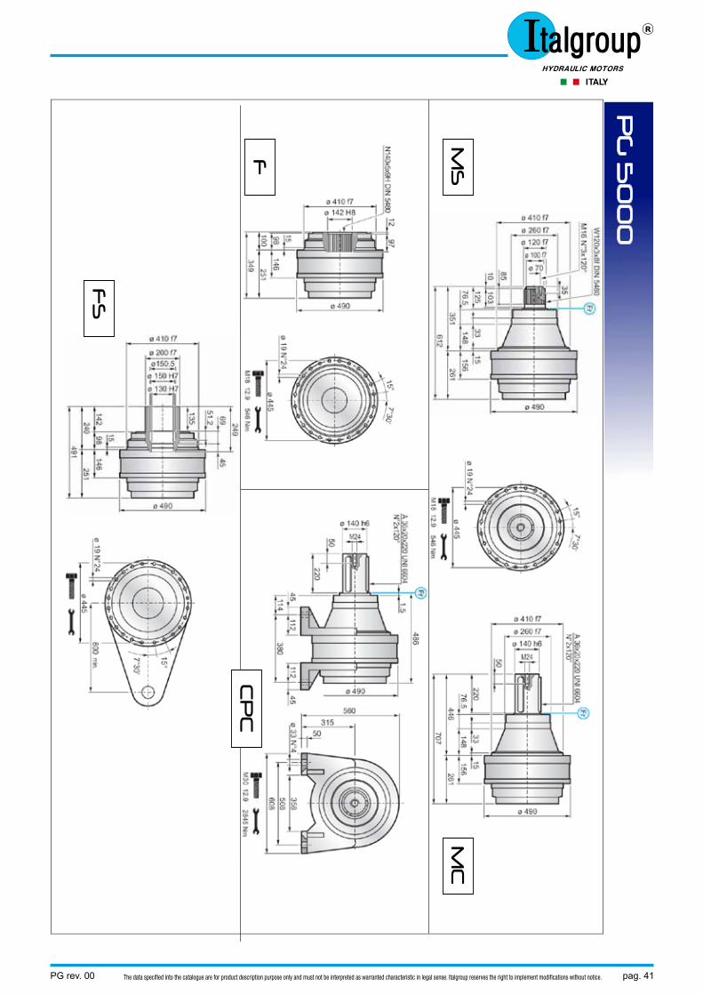
PG 5000
PG rev. 00 pag. 41The data specified into the catalogue are for product description purpose only and must not be interpreted as warranted characteristic in legal sense. Italgroup reserves the right to implement modifications without notice.
PG
50
00
MS
M
C
CP
C
FS
F
pag. 42 PG rev. 00The data specified into the catalogue are for product description purpose only and must not be interpreted as warranted characteristic in legal sense. Italgroup reserves the right to implement modifications without notice.
VERSIONI SPECIALI – SPECIAL VERSION
VERSIONE USCITA – OUTPUT TYPE ENTRATA TIPO INPUT TYPE
F MC – MS CPC FS
PG 5001 A 251 A 261 A 486 A 251 D PG 5002 A 358 A 368 A 593 A 358 B PG 5003 A 430 A 440 A 665 A 430 A PG 5004 A 491 A 501 A 726 A 491 A
VERSIONE USCITA – OUTPUT TYPE ENTRATA TIPO INPUT TYPE
F MC – MS CPC FS
PGA 5002 A 432 , B 315 A 442 , B 315 A 667 , B 315 A 432 , B 315 B PGA 5003 A 446 , B 240 A 456 , B 240 A 681 , B 240 A 446 , B 240 A PGA 5004 A 531 , B 240 A 541 , B 240 A 766 , B 240 A 531 , B 240 A
PG 5000
PG rev. 00 pag. 43The data specified into the catalogue are for product description purpose only and must not be interpreted as warranted characteristic in legal sense. Italgroup reserves the right to implement modifications without notice.
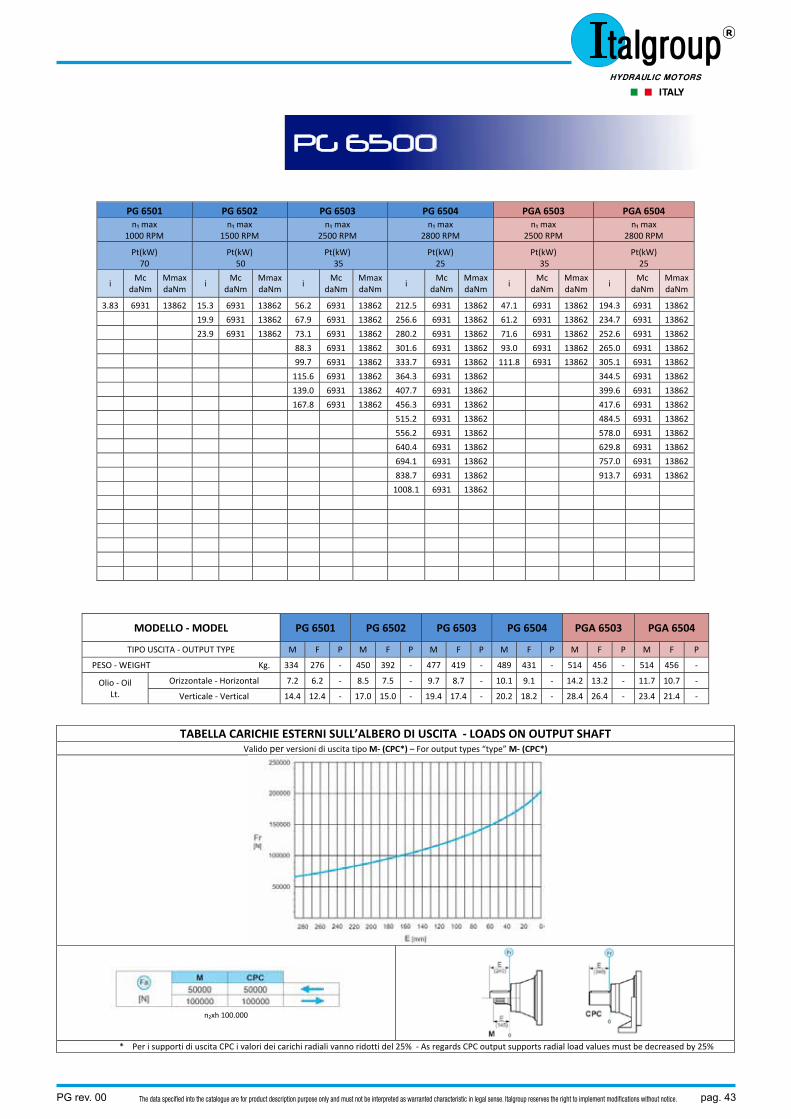
PG 6501 PG 6502 PG 6503 PG 6504 PGA 6503 PGA 6504 n₁ max
1000 RPM n₁ max
1500 RPM n₁ max
2500 RPM n₁ max
2800 RPM n₁ max
2500 RPM n₁ max
2800 RPM
Pt(kW) 70
Pt(kW) 50
Pt(kW) 35
Pt(kW) 25
Pt(kW) 35
Pt(kW) 25
i Mc
daNm Mmax daNm
i Mc
daNm Mmax daNm
i Mc
daNm MmaxdaNm
i Mc
daNm MmaxdaNm
i Mc
daNm Mmax daNm
i Mc
daNm MmaxdaNm
3.83 6931 13862 15.3 6931 13862 56.2 6931 13862 212.5 6931 13862 47.1 6931 13862 194.3 6931 13862
19.9 6931 13862 67.9 6931 13862 256.6 6931 13862 61.2 6931 13862 234.7 6931 13862
23.9 6931 13862 73.1 6931 13862 280.2 6931 13862 71.6 6931 13862 252.6 6931 13862
88.3 6931 13862 301.6 6931 13862 93.0 6931 13862 265.0 6931 13862
99.7 6931 13862 333.7 6931 13862 111.8 6931 13862 305.1 6931 13862
115.6 6931 13862 364.3 6931 13862 344.5 6931 13862
139.0 6931 13862 407.7 6931 13862 399.6 6931 13862
167.8 6931 13862 456.3 6931 13862 417.6 6931 13862
515.2 6931 13862 484.5 6931 13862
556.2 6931 13862 578.0 6931 13862
640.4 6931 13862 629.8 6931 13862
694.1 6931 13862 757.0 6931 13862
838.7 6931 13862 913.7 6931 13862
1008.1 6931 13862
MODELLO ‐ MODEL PG 6501 PG 6502 PG 6503 PG 6504 PGA 6503 PGA 6504
TIPO USCITA ‐ OUTPUT TYPE M F P M F P M F P M F P M F P M F P
PESO ‐ WEIGHT Kg. 334 276 ‐ 450 392 ‐ 477 419 ‐ 489 431 ‐ 514 456 ‐ 514 456 ‐
Olio ‐ Oil Lt.
Orizzontale ‐ Horizontal 7.2 6.2 ‐ 8.5 7.5 ‐ 9.7 8.7 ‐ 10.1 9.1 ‐ 14.2 13.2 ‐ 11.7 10.7 ‐
Verticale ‐ Vertical 14.4 12.4 ‐ 17.0 15.0 ‐ 19.4 17.4 ‐ 20.2 18.2 ‐ 28.4 26.4 ‐ 23.4 21.4 ‐
TABELLA CARICHIE ESTERNI SULL’ALBERO DI USCITA ‐ LOADS ON OUTPUT SHAFT Valido per versioni di uscita tipo M‐ (CPC*) – For output types “type” M‐ (CPC*)
n₂xh 100.000
* Per i supporti di uscita CPC i valori dei carichi radiali vanno ridotti del 25% ‐ As regards CPC output supports radial load values must be decreased by 25%
PG 6500
pag. 44 PG rev. 00The data specified into the catalogue are for product description purpose only and must not be interpreted as warranted characteristic in legal sense. Italgroup reserves the right to implement modifications without notice.
PG
65
00
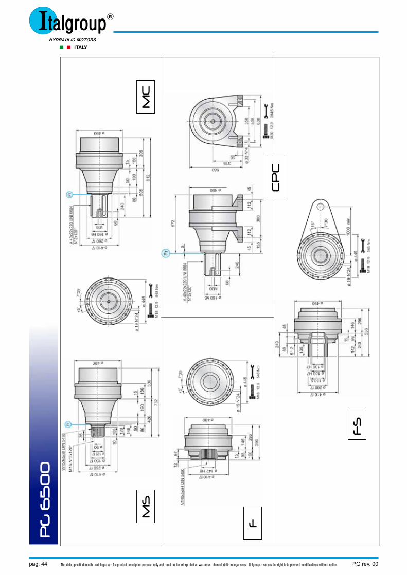
MS
M
C
CP
C
FS
F

PG rev. 00 pag. 45The data specified into the catalogue are for product description purpose only and must not be interpreted as warranted characteristic in legal sense. Italgroup reserves the right to implement modifications without notice.
VERSIONI SPECIALI – SPECIAL VERSION
VERSIONE USCITA – OUTPUT TYPE ENTRATA TIPO INPUT TYPE
F MC – MS CPC FS
PG 6501 A 296 A 306 A 572 A 296 ‐ PG 6502 A 478 A 488 A 754 A 478 C PG 6503 A 572 A 582 A 848 A 572 B PG 6504 A 632 A 642 A 908 A 632 A
VERSIONE USCITA – OUTPUT TYPE ENTRATA TIPO INPUT TYPE
F MC – MS CPC FS
PGA 6503 A 558 , B 315 A 568 , B 315 A 834 , B 315 A 558 , B 315 B PGA 6504 A 660 , B 240 A 670 , B 240 A 936 , B 240 A 660 , B 240 A
PG 6500
pag. 46 PG rev. 00The data specified into the catalogue are for product description purpose only and must not be interpreted as warranted characteristic in legal sense. Italgroup reserves the right to implement modifications without notice.
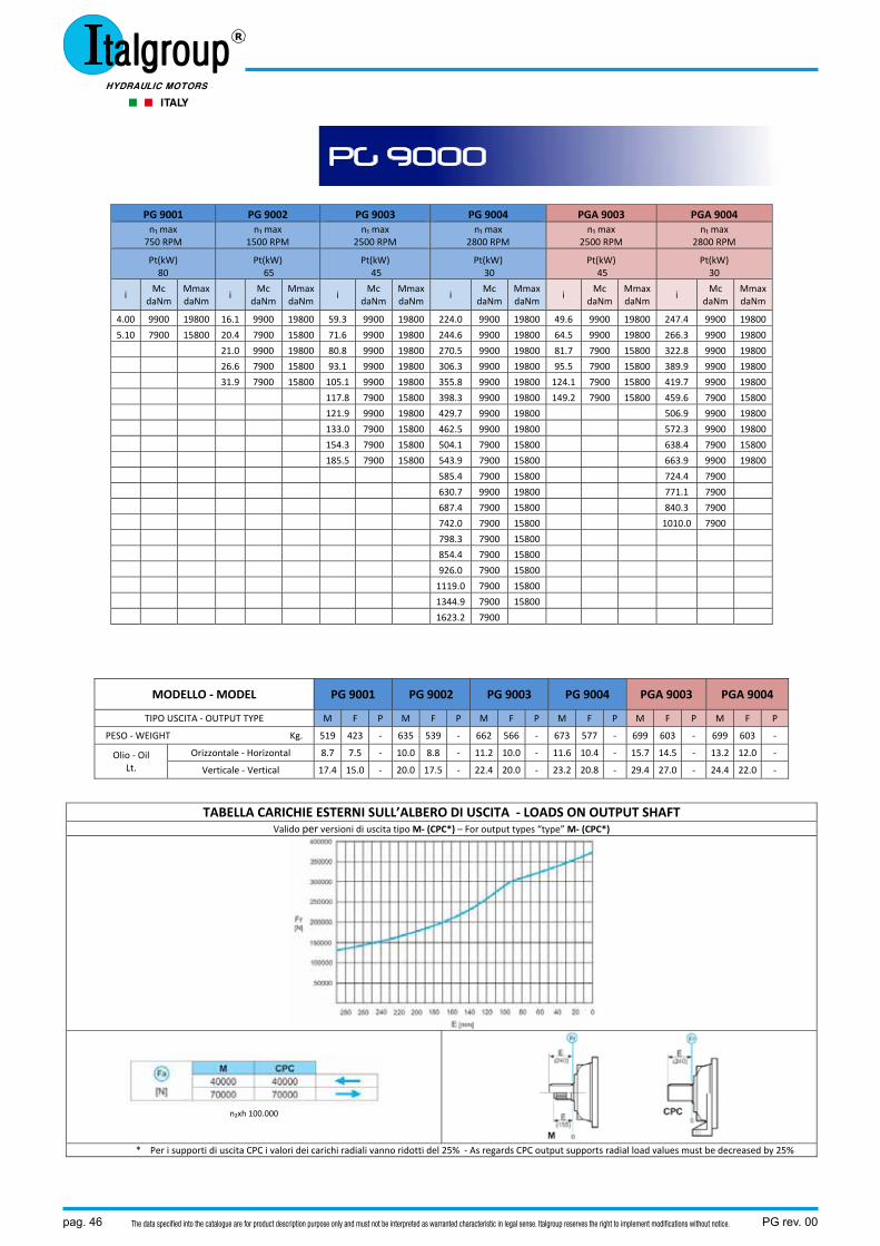
PG 9001 PG 9002 PG 9003 PG 9004 PGA 9003 PGA 9004 n₁ max 750 RPM
n₁ max 1500 RPM
n₁ max 2500 RPM
n₁ max 2800 RPM
n₁ max 2500 RPM
n₁ max 2800 RPM
Pt(kW) 80
Pt(kW) 65
Pt(kW) 45
Pt(kW) 30
Pt(kW) 45
Pt(kW) 30
i Mc
daNm Mmax daNm
i Mc
daNm Mmax daNm
i Mc
daNm MmaxdaNm
i Mc
daNm MmaxdaNm
i Mc
daNm Mmax daNm
i Mc
daNm MmaxdaNm
4.00 9900 19800 16.1 9900 19800 59.3 9900 19800 224.0 9900 19800 49.6 9900 19800 247.4 9900 19800
5.10 7900 15800 20.4 7900 15800 71.6 9900 19800 244.6 9900 19800 64.5 9900 19800 266.3 9900 19800
21.0 9900 19800 80.8 9900 19800 270.5 9900 19800 81.7 7900 15800 322.8 9900 19800
26.6 7900 15800 93.1 9900 19800 306.3 9900 19800 95.5 7900 15800 389.9 9900 19800
31.9 7900 15800 105.1 9900 19800 355.8 9900 19800 124.1 7900 15800 419.7 9900 19800
117.8 7900 15800 398.3 9900 19800 149.2 7900 15800 459.6 7900 15800
121.9 9900 19800 429.7 9900 19800 506.9 9900 19800
133.0 7900 15800 462.5 9900 19800 572.3 9900 19800
154.3 7900 15800 504.1 7900 15800 638.4 7900 15800
185.5 7900 15800 543.9 7900 15800 663.9 9900 19800
585.4 7900 15800 724.4 7900
630.7 9900 19800 771.1 7900
687.4 7900 15800 840.3 7900
742.0 7900 15800 1010.0 7900
798.3 7900 15800
854.4 7900 15800
926.0 7900 15800
1119.0 7900 15800
1344.9 7900 15800
1623.2 7900
MODELLO ‐ MODEL PG 9001 PG 9002 PG 9003 PG 9004 PGA 9003 PGA 9004
TIPO USCITA ‐ OUTPUT TYPE M F P M F P M F P M F P M F P M F P
PESO ‐ WEIGHT Kg. 519 423 ‐ 635 539 ‐ 662 566 ‐ 673 577 ‐ 699 603 ‐ 699 603 ‐
Olio ‐ Oil Lt.
Orizzontale ‐ Horizontal 8.7 7.5 ‐ 10.0 8.8 ‐ 11.2 10.0 ‐ 11.6 10.4 ‐ 15.7 14.5 ‐ 13.2 12.0 ‐
Verticale ‐ Vertical 17.4 15.0 ‐ 20.0 17.5 ‐ 22.4 20.0 ‐ 23.2 20.8 ‐ 29.4 27.0 ‐ 24.4 22.0 ‐
TABELLA CARICHIE ESTERNI SULL’ALBERO DI USCITA ‐ LOADS ON OUTPUT SHAFT Valido per versioni di uscita tipo M‐ (CPC*) – For output types “type” M‐ (CPC*)
n₂xh 100.000
* Per i supporti di uscita CPC i valori dei carichi radiali vanno ridotti del 25% ‐ As regards CPC output supports radial load values must be decreased by 25%
PG 9000
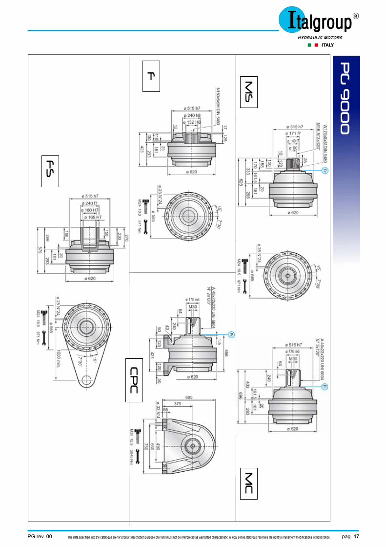
PG rev. 00 pag. 47The data specified into the catalogue are for product description purpose only and must not be interpreted as warranted characteristic in legal sense. Italgroup reserves the right to implement modifications without notice.
PG
90
00
MS
M
C
CP
C
FS
F

pag. 48 PG rev. 00The data specified into the catalogue are for product description purpose only and must not be interpreted as warranted characteristic in legal sense. Italgroup reserves the right to implement modifications without notice.
VERSIONI SPECIALI – SPECIAL VERSION
VERSIONE USCITA – OUTPUT TYPE ENTRATA TIPO INPUT TYPE
F MC – MS CPC FS
PG 9001 A 293 A 293 A 456 A 293 ‐ PG 9002 A 475 A 475 A 638 A 475 C PG 9003 A 569 A 569 A 732 A 569 B PG 9004 A 629 A 629 A 792 A 629 A
VERSIONE USCITA – OUTPUT TYPE ENTRATA TIPO INPUT TYPE
F MC – MS CPC FS
PGA 9003 A 555 , B 315 A 555 , B 315 A 718 , B 315 A 555 , B 315 B PGA 9004 A 657 , B 240 A 657 , B 240 A 820 , B 240 A 657 , B 240 A
PG 9000
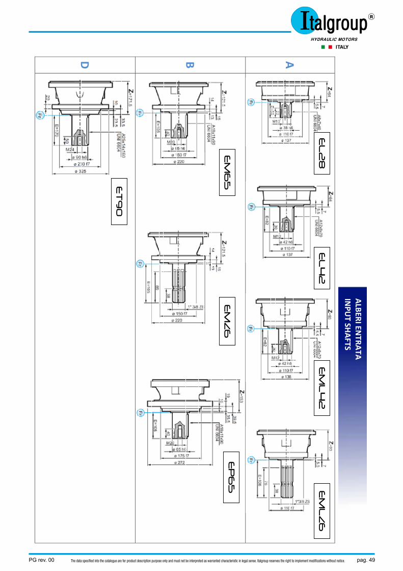
PG rev. 00 pag. 49The data specified into the catalogue are for product description purpose only and must not be interpreted as warranted characteristic in legal sense. Italgroup reserves the right to implement modifications without notice.
A
B
D
EL
28
EL
42
E
ML
42
E
ML
Z6
EM
65
E
MZ
6
EP
65
ET
90
ALBERI EN
TRATA
INPU
T SHAFTS
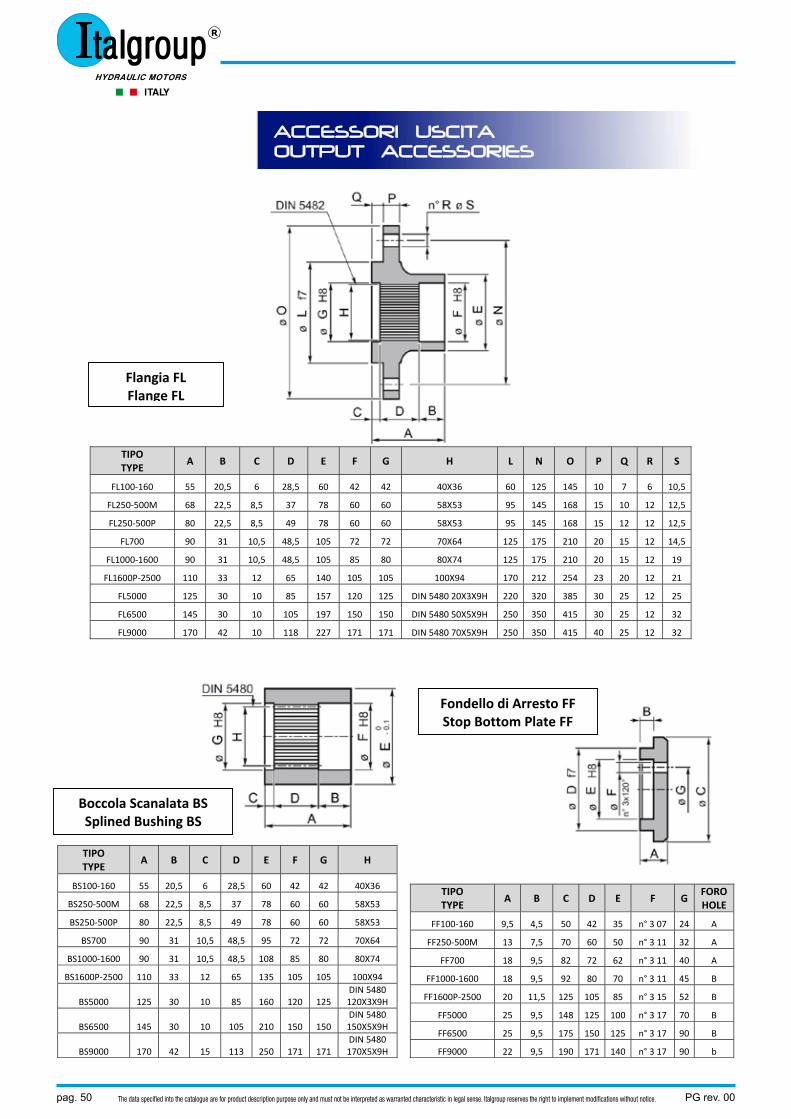
pag. 50 PG rev. 00The data specified into the catalogue are for product description purpose only and must not be interpreted as warranted characteristic in legal sense. Italgroup reserves the right to implement modifications without notice.
ACCESSORI USCITA OUTPUT ACCESSORIES
TIPO TYPE
A B C D E F G H L N O P Q R S
FL100‐160 55 20,5 6 28,5 60 42 42 40X36 60 125 145 10 7 6 10,5
FL250‐500M 68 22,5 8,5 37 78 60 60 58X53 95 145 168 15 10 12 12,5
FL250‐500P 80 22,5 8,5 49 78 60 60 58X53 95 145 168 15 12 12 12,5
FL700 90 31 10,5 48,5 105 72 72 70X64 125 175 210 20 15 12 14,5
FL1000‐1600 90 31 10,5 48,5 105 85 80 80X74 125 175 210 20 15 12 19
FL1600P‐2500 110 33 12 65 140 105 105 100X94 170 212 254 23 20 12 21
FL5000 125 30 10 85 157 120 125 DIN 5480 20X3X9H 220 320 385 30 25 12 25
FL6500 145 30 10 105 197 150 150 DIN 5480 50X5X9H 250 350 415 30 25 12 32
FL9000 170 42 10 118 227 171 171 DIN 5480 70X5X9H 250 350 415 40 25 12 32
TIPO TYPE
A B C D E F G H
BS100‐160 55 20,5 6 28,5 60 42 42 40X36
BS250‐500M 68 22,5 8,5 37 78 60 60 58X53
BS250‐500P 80 22,5 8,5 49 78 60 60 58X53
BS700 90 31 10,5 48,5 95 72 72 70X64
BS1000‐1600 90 31 10,5 48,5 108 85 80 80X74
BS1600P‐2500 110 33 12 65 135 105 105 100X94
BS5000 125 30 10 85 160 120 125 DIN 5480120X3X9H
BS6500 145 30 10 105 210 150 150 DIN 5480150X5X9H
BS9000 170 42 15 113 250 171 171 DIN 5480170X5X9H
TIPO TYPE
A B C D E F G FOROHOLE
FF100‐160 9,5 4,5 50 42 35 n° 3 07 24 A
FF250‐500M 13 7,5 70 60 50 n° 3 11 32 A
FF700 18 9,5 82 72 62 n° 3 11 40 A
FF1000‐1600 18 9,5 92 80 70 n° 3 11 45 B
FF1600P‐2500 20 11,5 125 105 85 n° 3 15 52 B
FF5000 25 9,5 148 125 100 n° 3 17 70 B
FF6500 25 9,5 175 150 125 n° 3 17 90 B
FF9000 22 9,5 190 171 140 n° 3 17 90 b
Flangia FL Flange FL
Fondello di Arresto FF Stop Bottom Plate FF
Boccola Scanalata BS Splined Bushing BS
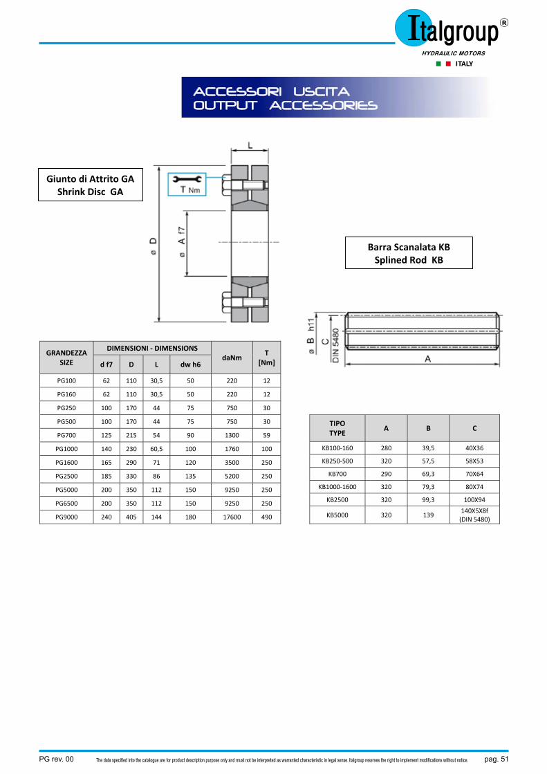
PG rev. 00 pag. 51The data specified into the catalogue are for product description purpose only and must not be interpreted as warranted characteristic in legal sense. Italgroup reserves the right to implement modifications without notice.
ACCESSORI USCITA OUTPUT ACCESSORIES
GRANDEZZA SIZE
DIMENSIONI ‐ DIMENSIONS daNm
T [Nm] d f7 D L dw h6
PG100 62 110 30,5 50 220 12
PG160 62 110 30,5 50 220 12
PG250 100 170 44 75 750 30
PG500 100 170 44 75 750 30
PG700 125 215 54 90 1300 59
PG1000 140 230 60,5 100 1760 100
PG1600 165 290 71 120 3500 250
PG2500 185 330 86 135 5200 250
PG5000 200 350 112 150 9250 250
PG6500 200 350 112 150 9250 250
PG9000 240 405 144 180 17600 490
TIPO TYPE
A B C
KB100‐160 280 39,5 40X36
KB250‐500 320 57,5 58X53
KB700 290 69,3 70X64
KB1000‐1600 320 79,3 80X74
KB2500 320 99,3 100X94
KB5000 320 139 140X5X8f(DIN 5480)
Barra Scanalata KB Splined Rod KB
Giunto di Attrito GA Shrink Disc GA
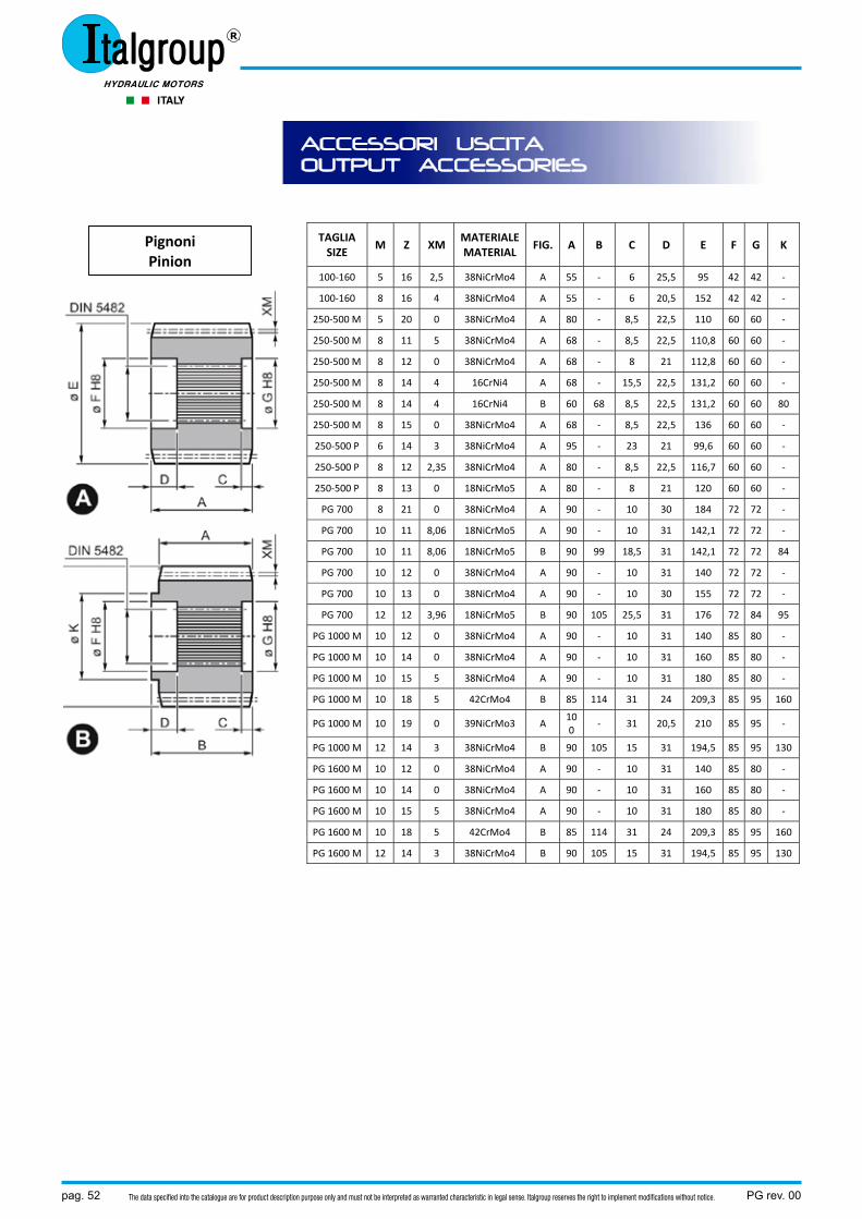
pag. 52 PG rev. 00The data specified into the catalogue are for product description purpose only and must not be interpreted as warranted characteristic in legal sense. Italgroup reserves the right to implement modifications without notice.
ACCESSORI USCITA OUTPUT ACCESSORIES
TAGLIA SIZE
M Z XM MATERIALEMATERIAL
FIG. A B C D E F G K
100‐160 5 16 2,5 38NiCrMo4 A 55 ‐ 6 25,5 95 42 42 ‐
100‐160 8 16 4 38NiCrMo4 A 55 ‐ 6 20,5 152 42 42 ‐
250‐500 M 5 20 0 38NiCrMo4 A 80 ‐ 8,5 22,5 110 60 60 ‐
250‐500 M 8 11 5 38NiCrMo4 A 68 ‐ 8,5 22,5 110,8 60 60 ‐
250‐500 M 8 12 0 38NiCrMo4 A 68 ‐ 8 21 112,8 60 60 ‐
250‐500 M 8 14 4 16CrNi4 A 68 ‐ 15,5 22,5 131,2 60 60 ‐
250‐500 M 8 14 4 16CrNi4 B 60 68 8,5 22,5 131,2 60 60 80
250‐500 M 8 15 0 38NiCrMo4 A 68 ‐ 8,5 22,5 136 60 60 ‐
250‐500 P 6 14 3 38NiCrMo4 A 95 ‐ 23 21 99,6 60 60 ‐
250‐500 P 8 12 2,35 38NiCrMo4 A 80 ‐ 8,5 22,5 116,7 60 60 ‐
250‐500 P 8 13 0 18NiCrMo5 A 80 ‐ 8 21 120 60 60 ‐
PG 700 8 21 0 38NiCrMo4 A 90 ‐ 10 30 184 72 72 ‐
PG 700 10 11 8,06 18NiCrMo5 A 90 ‐ 10 31 142,1 72 72 ‐
PG 700 10 11 8,06 18NiCrMo5 B 90 99 18,5 31 142,1 72 72 84
PG 700 10 12 0 38NiCrMo4 A 90 ‐ 10 31 140 72 72 ‐
PG 700 10 13 0 38NiCrMo4 A 90 ‐ 10 30 155 72 72 ‐
PG 700 12 12 3,96 18NiCrMo5 B 90 105 25,5 31 176 72 84 95
PG 1000 M 10 12 0 38NiCrMo4 A 90 ‐ 10 31 140 85 80 ‐
PG 1000 M 10 14 0 38NiCrMo4 A 90 ‐ 10 31 160 85 80 ‐
PG 1000 M 10 15 5 38NiCrMo4 A 90 ‐ 10 31 180 85 80 ‐
PG 1000 M 10 18 5 42CrMo4 B 85 114 31 24 209,3 85 95 160
PG 1000 M 10 19 0 39NiCrMo3 A 100
‐ 31 20,5 210 85 95 ‐
PG 1000 M 12 14 3 38NiCrMo4 B 90 105 15 31 194,5 85 95 130
PG 1600 M 10 12 0 38NiCrMo4 A 90 ‐ 10 31 140 85 80 ‐
PG 1600 M 10 14 0 38NiCrMo4 A 90 ‐ 10 31 160 85 80 ‐
PG 1600 M 10 15 5 38NiCrMo4 A 90 ‐ 10 31 180 85 80 ‐
PG 1600 M 10 18 5 42CrMo4 B 85 114 31 24 209,3 85 95 160
PG 1600 M 12 14 3 38NiCrMo4 B 90 105 15 31 194,5 85 95 130
Pignoni Pinion
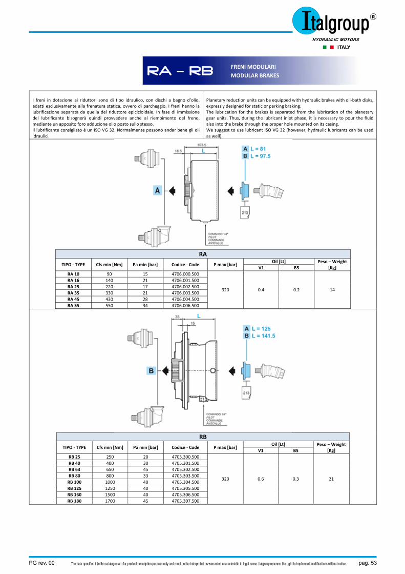
PG rev. 00 pag. 53The data specified into the catalogue are for product description purpose only and must not be interpreted as warranted characteristic in legal sense. Italgroup reserves the right to implement modifications without notice.
I freni in dotazione ai riduttori sono di tipo idraulico, con dischi a bagno d’olio, adatti esclusivamente alla frenatura statica, ovvero di parcheggio. I freni hanno la lubrificazione separata da quella del riduttore epicicloidale. In fase di immissione del lubrificante bisognerà quindi provvedere anche al riempimento del freno, mediante un apposito foro adduzione olio posto sullo stesso. Il lubrificante consigliato è un ISO VG 32. Normalmente possono andar bene gli oli idraulici.
Planetary reduction units can be equipped with hydraulic brakes with oil‐bath disks, expressly designed for static or parking braking. The lubrication for the brakes is separated from the lubrication of the planetary gear units. Thus, during the lubricant inlet phase, it is necessary to pour the fluid also into the brake through the proper hole mounted on its casing. We suggest to use lubricant ISO VG 32 (however, hydraulic lubricants can be used as well).
RA
TIPO ‐ TYPE Cfs min [Nm] Pa min [bar] Codice ‐ Code P max [bar] Oil [Lt] Peso – Weight
[Kg] V1 B5 RA 10 90 15 4706.000.500
320 0.4 0.2 14
RA 16 140 21 4706.001.500RA 25 220 17 4706.002.500RA 35 330 21 4706.003.500RA 45 430 28 4706.004.500RA 55 550 34 4706.006.500
RB
TIPO ‐ TYPE Cfs min [Nm] Pa min [bar] Codice ‐ Code P max [bar] Oil [Lt] Peso – Weight
[Kg] V1 B5 RB 25 250 20 4705.300.500
320 0.6 0.3 21
RB 40 400 30 4705.301.500RB 63 650 45 4705.302.500RB 80 800 33 4705.303.500RB 100 1000 40 4705.304.500RB 125 1250 40 4705.305.500RB 160 1500 40 4705.306.500RB 180 1700 45 4705.307.500
RA – RB FRENI MODULARI MODULAR BRAKES
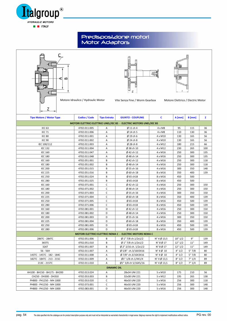
pag. 54 PG rev. 00The data specified into the catalogue are for product description purpose only and must not be interpreted as warranted characteristic in legal sense. Italgroup reserves the right to implement modifications without notice.
Predisposizione motori Motor Adaptors
Tipo Motore / Motor Type Codice / Code Tipo Entrata GIUNTO ‐ COUPLING C A [mm] B [mm] Z
MOTORI ELETTRICI ELETTRICI UNEL/IEC B5 ‐ ELECTRIC MOTORS UNEL/IEC B5
IEC 63 4702.011.005 A Ø 11 ch 4 4 x M8 95 115 36
IEC 71 4702.011.006 A Ø 14 ch 5 4 x M8 110 130 36
IEC 80 4702.011.001 A Ø 19 ch 6 4 x M10 130 165 56
IEC 90 4702.011.002 A Ø 24 ch 8 4 x M10 130 165 56
IEC 100/112 4702.011.003 A Ø 28 ch 8 4 x M12 180 215 66
IEC 132 4702.011.004 A Ø 38 ch 10 4 x M12 230 265 100
IEC 160 4702.011.047 A Ø 42 ch 12 4 x M16 250 300 135
IEC 180 4702.011.048 A Ø 48 ch 14 4 x M16 250 300 135
IEC 160 4702.051.001 B Ø 42 ch 12 4 x M16 250 300 118
IEC 180 4702.051.002 B Ø 48 ch 14 4 x M16 250 300 118
IEC 200 4702.051.015 B Ø 55 ch 16 4 x M16 300 350 148
IEC 225 4702.051.016 B Ø 60 ch 18 8 x M16 350 400 139
IEC 250 4702.051.024 B Ø 65 ch18 8 x M16 450 500
IEC 280 4702.051.025 B Ø 65 ch18 8 x M16 450 500
IEC 160 4702.071.001 C Ø 42 ch 12 4 x M16 250 300 150
IEC 180 4702.071.002 C Ø 48 ch 14 4 x M16 250 300 150
IEC 200 4702.071.003 C Ø 55 ch 16 4 x M16 300 350 150
IEC 225 4702.071.004 C Ø 60 ch 18 8 x M16 350 400 139
IEC 250 4702.071.005 C Ø 65 ch18 8 x M16 450 500 139
IEC 280 4702.071.006 C Ø 65 ch18 8 x M16 450 500 139
IEC 160 4702.081.001 D Ø 42 ch 12 4 x M16 250 300 150
IEC 180 4702.081.002 D Ø 48 ch 14 4 x M16 250 300 150
IEC 200 4702.081.003 D Ø 55 ch 16 4 x M16 300 350 150
IEC 225 4702.081.004 D Ø 60 ch 18 8 x M16 350 400 139
IEC 250 4702.081.005 D Ø 65 ch18 8 x M16 450 500 139
IEC 280 4702.081.006 D Ø 65 ch18 8 x M16 450 500 139
MOTORI ELETTRICI ELETTRICI NEMA C ‐ ELECTRIC MOTORS NEMA C
286TC ‐ 284TC 4702.051.006 B Ø 1" 7/8 ch.1/2x1/2 N° 4 Ø 13,5 10" 1/2 9" 139
365TS 4702.051.010 B Ø 1" 7/8 ch.1/2x1/2 N° 8 Ø 17 12" 1/2 11" 149
326T 4702.051.007 B Ø 2" 2/16 ch. 1/2x1/2 N° 8 Ø 17 12" 1/2 11" 149
56 ‐ 56H 4702.011.007 A Ø 5/8" ch.3/16X3X16 N° 4 Ø 10 4" 1/2 5" 7/8 80
143TC ‐ 145TC ‐ 182 ‐ 184C 4702.011.008 A Ø 7/8" ch.3/16X3X16 N° 4 Ø 10 4" 1/2 5" 7/8 80
182TC ‐ 184TC ‐ 213 ‐ 215C 4702.011.009 A Ø1" 1/8 ch.1/4X1/4 N° 4 Ø 13,5 8" 1/2 7" 1/4 89
213C ‐ 215TC 4702.011.010 A Ø1" 3/8 ch 5/16X5/16 N° 4 Ø 13,5 8" 1/2 7" 1/4 89
DINAMIC OIL
AH100 ‐ BH150 ‐ BH175 ‐ BH200 4702.013.024 A 28x34 UNI 221 5 x M10 175 210 56
CH250 ‐ DH300 ‐ DH350 4702.053.003 B 32x38 UNI 221 5 x M12 195 265 138
PH800 ‐ PH1250 ‐ MH 1000 4702.053.020 C 46x50 UNI 220 5 x M16 256 300 118
PH800 ‐ PH1250 ‐ MH 1000 4702.073.001 C 46x50 UNI 220 5 x M16 256 300 148
PH800 ‐ PH1250 ‐ MH 1000 4702.083.001 D 46x50 UNI 220 5 x M16 256 300 148
Vite Senza Fine / Worm Gearbox Motore Elettrico / Electric Motor Motore Idraulico / Hydraulic Motor
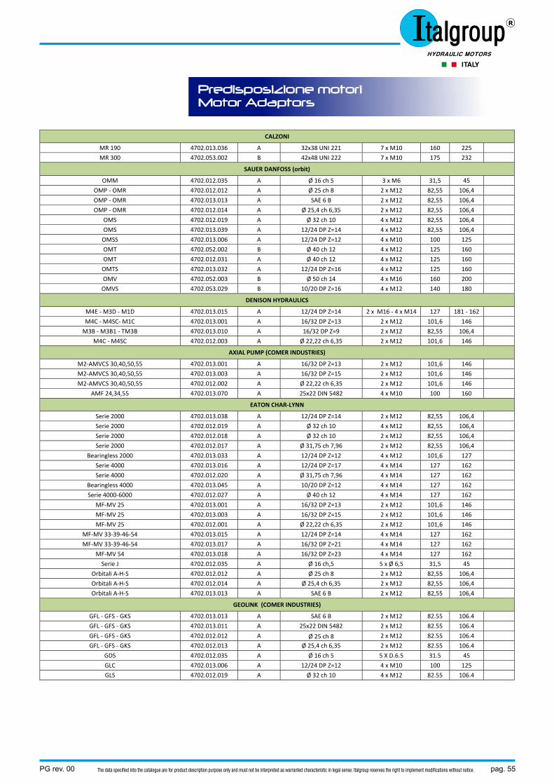
PG rev. 00 pag. 55The data specified into the catalogue are for product description purpose only and must not be interpreted as warranted characteristic in legal sense. Italgroup reserves the right to implement modifications without notice.
Predisposizione motori Motor Adaptors
CALZONI
MR 190 4702.013.036 A 32x38 UNI 221 7 x M10 160 225
MR 300 4702.053.002 B 42x48 UNI 222 7 x M10 175 232
SAUER DANFOSS (orbit)
OMM 4702.012.035 A Ø 16 ch 5 3 x M6 31,5 45
OMP ‐ OMR 4702.012.012 A Ø 25 ch 8 2 x M12 82,55 106,4
OMP ‐ OMR 4702.013.013 A SAE 6 B 2 x M12 82,55 106,4
OMP ‐ OMR 4702.012.014 A Ø 25,4 ch 6,35 2 x M12 82,55 106,4
OMS 4702.012.019 A Ø 32 ch 10 4 x M12 82,55 106,4
OMS 4702.013.039 A 12/24 DP Z=14 4 x M12 82,55 106,4
OMSS 4702.013.006 A 12/24 DP Z=12 4 x M10 100 125
OMT 4702.052.002 B Ø 40 ch 12 4 x M12 125 160
OMT 4702.012.031 A Ø 40 ch 12 4 x M12 125 160
OMTS 4702.013.032 A 12/24 DP Z=16 4 x M12 125 160
OMV 4702.052.003 B Ø 50 ch 14 4 x M16 160 200
OMVS 4702.053.029 B 10/20 DP Z=16 4 x M12 140 180
DENISON HYDRAULICS
M4E ‐ M3D ‐ M1D 4702.013.015 A 12/24 DP Z=14 2 x M16 ‐ 4 x M14 127 181 ‐ 162
M4C ‐ M4SC‐ M1C 4702.013.001 A 16/32 DP Z=13 2 x M12 101,6 146
M3B ‐ M3B1 ‐ TM3B 4702.013.010 A 16/32 DP Z=9 2 x M12 82,55 106,4
M4C ‐ M4SC 4702.012.003 A Ø 22,22 ch 6,35 2 x M12 101,6 146
AXIAL PUMP (COMER INDUSTRIES)
M2‐AMVCS 30,40,50,55 4702.013.001 A 16/32 DP Z=13 2 x M12 101,6 146
M2‐AMVCS 30,40,50,55 4702.013.003 A 16/32 DP Z=15 2 x M12 101,6 146
M2‐AMVCS 30,40,50,55 4702.012.002 A Ø 22,22 ch 6,35 2 x M12 101,6 146
AMF 24,34,55 4702.013.070 A 25x22 DIN 5482 4 x M10 100 160
EATON CHAR‐LYNN
Serie 2000 4702.013.038 A 12/24 DP Z=14 2 x M12 82,55 106,4
Serie 2000 4702.012.019 A Ø 32 ch 10 4 x M12 82,55 106,4
Serie 2000 4702.012.018 A Ø 32 ch 10 2 x M12 82,55 106,4
Serie 2000 4702.012.017 A Ø 31,75 ch 7,96 2 x M12 82,55 106,4
Bearingless 2000 4702.013.033 A 12/24 DP Z=12 4 x M12 101,6 127
Serie 4000 4702.013.016 A 12/24 DP Z=17 4 x M14 127 162
Serie 4000 4702.012.020 A Ø 31,75 ch 7,96 4 x M14 127 162
Bearingless 4000 4702.013.045 A 10/20 DP Z=12 4 x M14 127 162
Serie 4000‐6000 4702.012.027 A Ø 40 ch 12 4 x M14 127 162
MF‐MV 25 4702.013.001 A 16/32 DP Z=13 2 x M12 101,6 146
MF‐MV 25 4702.013.003 A 16/32 DP Z=15 2 x M12 101,6 146
MF‐MV 25 4702.012.001 A Ø 22,22 ch 6,35 2 x M12 101,6 146
MF‐MV 33‐39‐46‐54 4702.013.015 A 12/24 DP Z=14 4 x M14 127 162
MF‐MV 33‐39‐46‐54 4702.013.017 A 16/32 DP Z=21 4 x M14 127 162
MF‐MV 54 4702.013.018 A 16/32 DP Z=23 4 x M14 127 162
Serie J 4702.012.035 A Ø 16 ch,5 5 x Ø 6,5 31,5 45
Orbitali A‐H‐S 4702.012.012 A Ø 25 ch 8 2 x M12 82,55 106,4
Orbitali A‐H‐S 4702.012.014 A Ø 25,4 ch 6,35 2 x M12 82,55 106,4
Orbitali A‐H‐S 4702.013.013 A SAE 6 B 2 x M12 82,55 106,4
GEOLINK (COMER INDUSTRIES)
GFL ‐ GFS ‐ GKS 4702.013.013 A SAE 6 B 2 x M12 82.55 106.4
GFL ‐ GFS ‐ GKS 4702.013.011 A 25x22 DIN 5482 2 x M12 82.55 106.4
GFL ‐ GFS ‐ GKS 4702.012.012 A Ø 25 ch 8 2 x M12 82.55 106.4
GFL ‐ GFS ‐ GKS 4702.012.013 A Ø 25,4 ch 6,35 2 x M12 82.55 106.4
GDS 4702.012.035 A Ø 16 ch 5 5 X D.6.5 31.5 45
GLC 4702.013.006 A 12/24 DP Z=12 4 x M10 100 125
GLS 4702.012.019 A Ø 32 ch 10 4 x M12 82.55 106.4
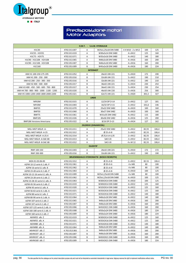
pag. 56 PG rev. 00The data specified into the catalogue are for product description purpose only and must not be interpreted as warranted characteristic in legal sense. Italgroup reserves the right to implement modifications without notice.
Predisposizione motori Motor Adaptors
H.M.T. ‐ S.A.M. HYDRAULIK
H1C30 4702.013.007 A W25x1,25x18 DIN 5480 4 X M10 ‐ 2 x M12 100 125
H1C55 ‐ H2V55 4702.013.019 A W30x2x14 DIN 5480 4 x M12 125 160
H1C75 ‐ H2V75 4702.013.071 A W35x2x16 DIN 5480 4 x M12 140 180
H1C90 ‐ H1C108 ‐ H2V108 4702.013.065 A N40x2x18 DIN 5480 4 x M16 160 200
H1C90 ‐ H1C108 ‐ H2V108 4702.053.007 B N40x2x18 DIN 5480 4 x M16 160 200
H1C160 4702.053.009 B W45x2x18 DIN 5480 4 x M16 180 224
INTERMOT
IAM H1 100‐150‐175‐195 4702.013.052 A 26x32 UNI 221 5 x M10 172 190
IAM H1 200 ‐ 250 ‐ 300 4702.053.016 B 32x38 UNI 221 5 x M12 190 210
IAM H2 200 ‐ 250 ‐ 300 ‐ 350 4702.053.016 B 32x38 UNI 221 5 x M12 190 210
IAM H2 400 ‐ 500 ‐ 600 4702.053.017 B 36x42 UNI 221 5 x M14 230 254
IAM H3 400 ‐ 450 ‐ 500 ‐ 600 ‐ 700 ‐ 800 4702.053.017 B 36x42 UNI 221 5 x M14 230 254
IAM H4 700 ‐ 800 ‐ 900 ‐ 1000 ‐ 1100 ‐ 1200 4702.053.020 B 46x50 UNI 220 5 x M16 256 300
IAM H5 1000‐1200‐1400‐1800‐2000‐2200 4702.053.021 B 62x72 UNI 221 5 x M20 301,5 327
LINDE
MF63M 4702.013.015 A 12/24 DP Z=14 2 x M12 127 181
MF43M 4702.013.003 A 16/32 DP Z=15 2 x M12 101,6 146
BMF35 4702.013.070 A 25x22 DIN 5482 4 x M10 100 160
BMF50 4702.013.060 A 30x27 DIN 5482 4 x M10 100 160
BMF75 4702.013.061 A W31x35 DIN 5482 4 x M12 115 180
BMF105 4702.013.026 A 40x36 DIN 5482 4 x M16 125 200
BMF186 Versione Americana 4702.053.022 B 8/16 DP Z=13 4 x M14 127 162
OILDRIVE (DINAMICOIL)
MGL‐MGT‐MGLR ‐A‐ 4702.013.011 A 25x22 DIN 5482 2 x M12 82,55 106,4
MGL‐MGT‐MGLR ‐A‐25 4702.012.012 A Ø 25 ch 8 2 x M12 82,55 106,4
MGL‐MGT‐MGLR ‐A‐25.4 4702.012.014 A Ø 25,4 ch 6,35 2 x M12 82,55 106,4
MGL‐MGT MGLR ‐A‐SAE 6B 4702.013.013 A SAE 6 B 2 x M12 82,55 106,4
MGL‐MGT‐MGLR ‐B‐SAE 6B 4702.013.012 A SAE 6 B 4 x M 12 82,55 106,4
OLIOSTIP
RMF 100‐150 4702.013.043 A 26x32 UNI 221 5 x M10 172 172
RMF 200‐300 4702.053.016 B 32x38 UNI 221 5 x M12 190 190
BRUENINGHAUS HYDROMATIK (BOSCH REXROTH)
MZA 01‐03‐06‐00 4702.012.012 A Ø 25 ch 8 2 x M12 82.55 106.4
A2FM 10‐12 serie 6.1 alb. P 4702.012.061 A Ø 20 ch 6 4 x M8 80 100
A2FM 16 serie 6.1 alb. B 4702.012.062 A Ø 25 ch 8 4 x M8 80 100
A2FM 23‐28 serie 6.1 alb. P 4702.012.063 A Ø 25 ch 8 4 x M10 100 125
A2FM 10‐12‐16 serie 6.1 alb. A 4702.013.009 A W25x1,25x18 DIN 5480 4 x M8 80 100
A2FM 23‐28 serie 6.1 alb. Z 4702.013.062 A W25x1,25x18 DIN 5480 4 x M10 100 125
A2FM 23‐28‐32 serie 6.1 alb. A 4702.013.063 A W30X2X14 DIN 5480 4 x M10 100 125
A2FM 45‐56 serie 6.1 alb. Z 4702.013.019 A W30X2X14 DIN 5480 4 x M12 125 160
A2FM 45 serie 6.1 alb. A 4702.013.020 A W32X2X14 DIN 5480 4 x M12 125 160
A2FM 56‐63 serie 6.1 alb. A 4702.013.021 A W35X2X16 DIN 5480 4 x M12 125 160
A2FM 80 serie 6.1 alb. Z 4702.013.071 A W35X2X16 DIN 5480 4 x M12 140 180
A2FM 80‐90 serie 6.1 alb. A 4702.013.064 A N40x2x18 DIN 5480 4 x M12 140 180
A2FM 107 serie 6.1 alb. Z 4702.013.065 A N40x2x18 DIN 5480 4 x M16 160 200
A2FM 107 serie 6.1 alb. Z 4702.053.007 B N40x2x18 DIN 5480 4 x M16 160 200
A2FM 107‐125 serie 6.1 alb. A 4702.053.006 B W45X2X21 DIN 5480 4 x M16 160 200
A2FM 160‐180 serie 6.1 alb. A 4702.053.008 B W50x2x24 DIN 5480 4 x M16 180 224
A2FM 160 serie 6.1 alb. Z 4702.053.009 B W50x2x24 DIN 5480 4 x M16 180 224
A6VM55 alb. Z 4702.013.019 A W30X2X14 DIN 5480 4 x M12 125 160
A6VM55 alb. A 4702.013.021 A W35X2X16 DIN 5480 4 x M12 125 160
A6VM80 alb. Z 4702.013.071 A W35X2X16 DIN 5480 4 x M12 140 180
A6VM80 alb. A 4702.013.064 A N40x2x18 DIN 5480 4 x M12 140 180
A6VM107 alb. Z 4.702.013.065 A N40x2x18 DIN 5480 4 x M16 160 200
A6VM107 alb. Z 4702.053.007 B N40x2x18 DIN 5480 4 x M16 160 200
A6VM107 alb. A 4702.053.006 B W45X2X21 DIN 5480 4 x M16 160 200
A6VM160 alb. Z 4702.053.009 B W45X2X21 DIN 5480 4 x M16 180 224
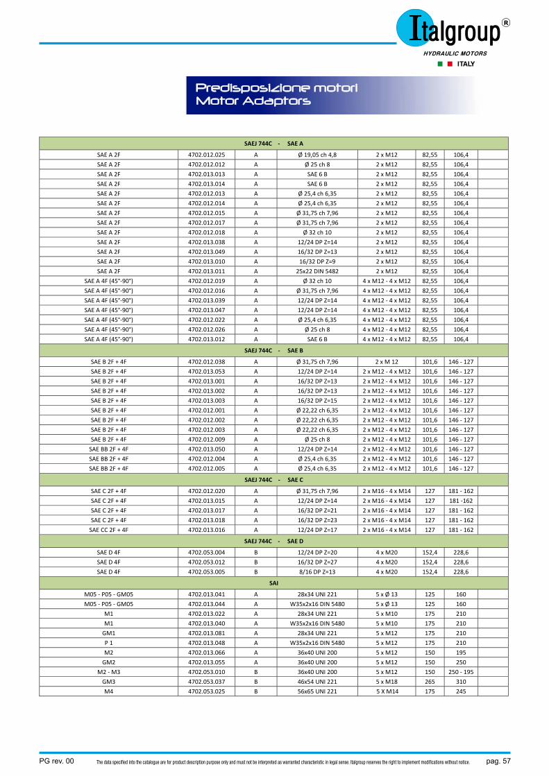
PG rev. 00 pag. 57The data specified into the catalogue are for product description purpose only and must not be interpreted as warranted characteristic in legal sense. Italgroup reserves the right to implement modifications without notice.
Predisposizione motori Motor Adaptors
SAEJ 744C ‐ SAE A
SAE A 2F 4702.012.025 A Ø 19,05 ch 4,8 2 x M12 82,55 106,4
SAE A 2F 4702.012.012 A Ø 25 ch 8 2 x M12 82,55 106,4
SAE A 2F 4702.013.013 A SAE 6 B 2 x M12 82,55 106,4
SAE A 2F 4702.013.014 A SAE 6 B 2 x M12 82,55 106,4
SAE A 2F 4702.012.013 A Ø 25,4 ch 6,35 2 x M12 82,55 106,4
SAE A 2F 4702.012.014 A Ø 25,4 ch 6,35 2 x M12 82,55 106,4
SAE A 2F 4702.012.015 A Ø 31,75 ch 7,96 2 x M12 82,55 106,4
SAE A 2F 4702.012.017 A Ø 31,75 ch 7,96 2 x M12 82,55 106,4
SAE A 2F 4702.012.018 A Ø 32 ch 10 2 x M12 82,55 106,4
SAE A 2F 4702.013.038 A 12/24 DP Z=14 2 x M12 82,55 106,4
SAE A 2F 4702.013.049 A 16/32 DP Z=13 2 x M12 82,55 106,4
SAE A 2F 4702.013.010 A 16/32 DP Z=9 2 x M12 82,55 106,4
SAE A 2F 4702.013.011 A 25x22 DIN 5482 2 x M12 82,55 106,4
SAE A 4F (45°‐90°) 4702.012.019 A Ø 32 ch 10 4 x M12 ‐ 4 x M12 82,55 106,4
SAE A 4F (45°‐90°) 4702.012.016 A Ø 31,75 ch 7,96 4 x M12 ‐ 4 x M12 82,55 106,4
SAE A 4F (45°‐90°) 4702.013.039 A 12/24 DP Z=14 4 x M12 ‐ 4 x M12 82,55 106,4
SAE A 4F (45°‐90°) 4702.013.047 A 12/24 DP Z=14 4 x M12 ‐ 4 x M12 82,55 106,4
SAE A 4F (45°‐90°) 4702.012.022 A Ø 25,4 ch 6,35 4 x M12 ‐ 4 x M12 82,55 106,4
SAE A 4F (45°‐90°) 4702.012.026 A Ø 25 ch 8 4 x M12 ‐ 4 x M12 82,55 106,4
SAE A 4F (45°‐90°) 4702.013.012 A SAE 6 B 4 x M12 ‐ 4 x M12 82,55 106,4
SAEJ 744C ‐ SAE B
SAE B 2F + 4F 4702.012.038 A Ø 31,75 ch 7,96 2 x M 12 101,6 146 ‐ 127
SAE B 2F + 4F 4702.013.053 A 12/24 DP Z=14 2 x M12 ‐ 4 x M12 101,6 146 ‐ 127
SAE B 2F + 4F 4702.013.001 A 16/32 DP Z=13 2 x M12 ‐ 4 x M12 101,6 146 ‐ 127
SAE B 2F + 4F 4702.013.002 A 16/32 DP Z=13 2 x M12 ‐ 4 x M12 101,6 146 ‐ 127
SAE B 2F + 4F 4702.013.003 A 16/32 DP Z=15 2 x M12 ‐ 4 x M12 101,6 146 ‐ 127
SAE B 2F + 4F 4702.012.001 A Ø 22,22 ch 6,35 2 x M12 ‐ 4 x M12 101,6 146 ‐ 127
SAE B 2F + 4F 4702.012.002 A Ø 22,22 ch 6,35 2 x M12 ‐ 4 x M12 101,6 146 ‐ 127
SAE B 2F + 4F 4702.012.003 A Ø 22,22 ch 6,35 2 x M12 ‐ 4 x M12 101,6 146 ‐ 127
SAE B 2F + 4F 4702.012.009 A Ø 25 ch 8 2 x M12 ‐ 4 x M12 101,6 146 ‐ 127
SAE BB 2F + 4F 4702.013.050 A 12/24 DP Z=14 2 x M12 ‐ 4 x M12 101,6 146 ‐ 127
SAE BB 2F + 4F 4702.012.004 A Ø 25,4 ch 6,35 2 x M12 ‐ 4 x M12 101,6 146 ‐ 127
SAE BB 2F + 4F 4702.012.005 A Ø 25,4 ch 6,35 2 x M12 ‐ 4 x M12 101,6 146 ‐ 127
SAEJ 744C ‐ SAE C
SAE C 2F + 4F 4702.012.020 A Ø 31,75 ch 7,96 2 x M16 ‐ 4 x M14 127 181 ‐ 162
SAE C 2F + 4F 4702.013.015 A 12/24 DP Z=14 2 x M16 ‐ 4 x M14 127 181 ‐162
SAE C 2F + 4F 4702.013.017 A 16/32 DP Z=21 2 x M16 ‐ 4 x M14 127 181 ‐ 162
SAE C 2F + 4F 4702.013.018 A 16/32 DP Z=23 2 x M16 ‐ 4 x M14 127 181 ‐ 162
SAE CC 2F + 4F 4702.013.016 A 12/24 DP Z=17 2 x M16 ‐ 4 x M14 127 181 ‐ 162
SAEJ 744C ‐ SAE D
SAE D 4F 4702.053.004 B 12/24 DP Z=20 4 x M20 152,4 228,6
SAE D 4F 4702.053.012 B 16/32 DP Z=27 4 x M20 152,4 228,6
SAE D 4F 4702.053.005 B 8/16 DP Z=13 4 x M20 152,4 228,6
SAI
M05 ‐ P05 ‐ GM05 4702.013.041 A 28x34 UNI 221 5 x Ø 13 125 160
M05 ‐ P05 ‐ GM05 4702.013.044 A W35x2x16 DIN 5480 5 x Ø 13 125 160
M1 4702.013.022 A 28x34 UNI 221 5 x M10 175 210
M1 4702.013.040 A W35x2x16 DIN 5480 5 x M10 175 210
GM1 4702.013.081 A 28x34 UNI 221 5 x M12 175 210
P 1 4702.013.048 A W35x2x16 DIN 5480 5 x M12 175 210
M2 4702.013.066 A 36x40 UNI 200 5 x M12 150 195
GM2 4702.013.055 A 36x40 UNI 200 5 x M12 150 250
M2 ‐ M3 4702.053.010 B 36x40 UNI 200 5 x M12 150 250 ‐ 195
GM3 4702.053.037 B 46x54 UNI 221 5 x M18 265 310
M4 4702.053.025 B 56x65 UNI 221 5 X M14 175 245
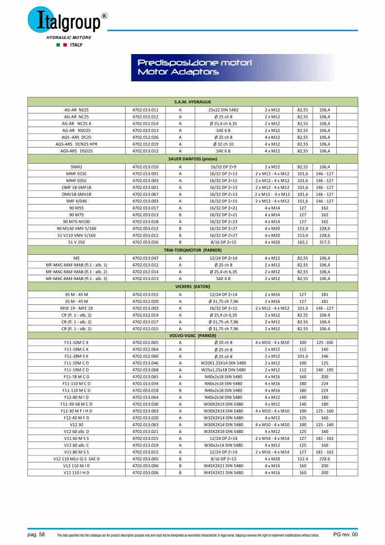
pag. 58 PG rev. 00The data specified into the catalogue are for product description purpose only and must not be interpreted as warranted characteristic in legal sense. Italgroup reserves the right to implement modifications without notice.
Predisposizione motori Motor Adaptors
S.A.M. HYDRAULIK
AG‐AR NS25 4702.013.011 A 25x22 DIN 5482 2 x M12 82,55 106,4
AG‐AR NC25 4702.012.012 A Ø 25 ch 8 2 x M12 82,55 106,4
AG‐AR NC25.4 4702.012.014 A Ø 25,4 ch 6,35 2 x M12 82,55 106,4
AG‐AR NSD25 4702.013.013 A SAE 6 B 2 x M12 82,55 106,4
AGS ‐ARS DC25 4702.012.026 A Ø 25 ch 8 4 x M12 82,55 106,4
AGS‐ARS DCN25 HPR 4702.012.019 A Ø 32 ch 10 4 x M12 82,55 106,4
AGS‐ARS DSD25 4702.013.012 A SAE 6 B 4 x M12 82,55 106,4
SAUER DANFOSS (piston)
SNM2 4702.013.010 A 16/32 DP Z=9 2 x M12 82,55 106,4
MMF 023C 4702.013.001 A 16/32 DP Z=13 2 x M12 ‐ 4 x M12 101,6 146 ‐ 127
MMF 035C 4702.013.003 A 16/32 DP Z=15 2 x M12 ‐ 4 x M12 101,6 146 ‐ 127
OMF 18‐SMF18 4702.013.001 A 16/32 DP Z=13 2 x M12 ‐ 4 x M12 101,6 146 ‐ 127
OMV18‐SMV18 4702.013.067 A 16/32 DP Z=13 2 x M12 ‐ 4 x M12 101,6 146 ‐ 127
SMF 4/046 4702.013.003 A 16/32 DP Z=15 2 x M12 ‐ 4 x M12 101,6 146 ‐ 127
90 M55 4702.013.017 A 16/32 DP Z=21 4 x M14 127 162
90 M75 4702.053.013 B 16/32 DP Z=21 4 x M14 127 162
90 M75‐M100 4702.013.018 A 16/32 DP Z=23 4 x M14 127 162
90 M130 VMV 5/160 4702.053.012 B 16/32 DP Z=27 4 x M20 152,4 228,6
51 V110 VMV 5/160 4702.053.012 B 16/32 DP Z=27 4 x M20 152,4 228,6
51 V 250 4702.053.026 B 8/16 DP Z=15 4 x M20 165,1 317,5
TRW‐TORQMOTOR (PARKER)
ME 4702.013.047 A 12/24 DP Z=14 4 x M12 82,55 106,4
MF‐MAC‐MAF‐MAB (fl.1 ‐ alb. 1) 4702.013.012 A Ø 25 ch 8 2 x M12 82,55 106,4
MF‐MAC‐MAF‐MAB (fl.1 ‐ alb. 2) 4702.012.014 A Ø 25,4 ch 6,35 2 x M12 82,55 106,4
MF‐MAC‐MAF‐MAB (fl.1 ‐ alb. 3) 4702.013.013 A SAE 6 B 2 x M12 82,55 106,4
VICKERS (EATON)
35 M ‐ 45 M 4702.013.015 A 12/24 DP Z=14 2 x M16 127 181
35 M ‐ 45 M 4702.012.020 A Ø 31,75 ch 7,96 2 x M16 127 181
MVE 19 ‐ MFE 19 4702.013.003 A 16/32 DP Z=15 2 x M12 ‐ 4 x M12 101.6 146 ‐ 127
CR (fl. 1 ‐ alb. 2) 4702.012.014 A Ø 25,4 ch 6,35 2 x M12 82.55 106.4
CR (fl. 1 ‐ alb. 2) 4702.012.017 A Ø 31,75 ch 7,96 2 x M12 82.55 106.4
CR (fl. 1 ‐ alb. 2) 4702.012.015 A Ø 31,75 ch 7,96 2 x M12 82.55 106.4
VOLVO‐VOAC (PARKER)
F11‐10M C K 4702.012.065 A Ø 20 ch 8 4 x M10 ‐ 4 x M10 100 125 ‐160
F11‐19M C K 4702.012.064 A Ø 25 ch 8 2 x M12 112 140
F11‐28M S K 4702.012.060 A Ø 25 ch 8 2 x M12 101.6 146
F11‐10M C D 4702.013.046 A W20X1.25X14 DIN 5480 2 x M12 100 125
F11‐19M C D 4702.013.068 A W25x1,25x18 DIN 5480 2 x M12 112 140 ‐ 195
F11‐78 M C D 4702.013.065 A N40x2x18 DIN 5480 4 x M16 160 200
F11‐110 M C D 4702.013.034 A N40x2x18 DIN 5480 4 x M16 180 224
F11‐110 M C D 4702.053.018 B N40x2x18 DIN 5480 4 x M16 180 224
F12‐80 M I D 4702.013.064 A N40x2x18 DIN 5480 4 x M12 140 180
F11‐39‐58 M C D 4702.013.030 A W30X2X14 DIN 5480 4 x M12 140 180
F12‐30 M F I H D 4702.013.063 A W30X2X14 DIN 5480 4 x M10 ‐ 4 x M10 100 125 ‐ 160
F12‐40 M F D 4702.013.020 A W32X2X14 DIN 5480 4 x M12 125 160
V12 30 4702.013.063 A W30X2X14 DIN 5480 4 x M10 ‐ 4 x M10 100 125 ‐ 160
V12 60 alb. D 4702.013.021 A W35X2X16 DIN 5480 4 x M12 125 160
V11 60 M S S 4702.013.015 A 12/24 DP Z=14 2 x M16 ‐ 4 x M14 127 181 ‐ 162
V12 60 alb. C 4702.013.019 A W30x2x14 DIN 5480 4 x M12 125 160
V11 80 M S S 4702.013.015 A 12/24 DP Z=14 2 x M16 ‐ 4 x M14 127 181 ‐ 162
V12 110 M(U‐S) S SAE D 4702.053.005 B 8/16 DP Z=13 4 x M20 152.4 228.6
V12 110 M I D 4702.053.006 B W45X2X21 DIN 5480 4 x M16 160 200
V12 110 I H D 4702.053.006 B W45X2X21 DIN 5480 4 x M16 160 200
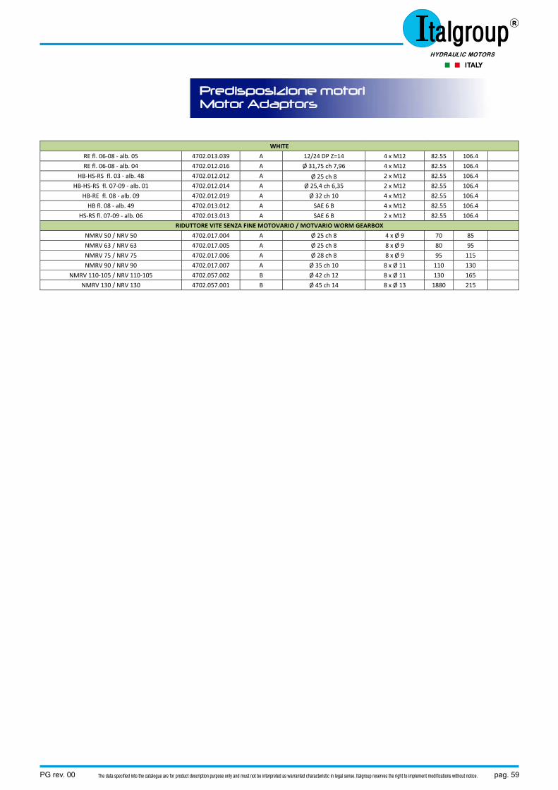
PG rev. 00 pag. 59The data specified into the catalogue are for product description purpose only and must not be interpreted as warranted characteristic in legal sense. Italgroup reserves the right to implement modifications without notice.
Predisposizione motori Motor Adaptors
WHITE
RE fl. 06‐08 ‐ alb. 05 4702.013.039 A 12/24 DP Z=14 4 x M12 82.55 106.4
RE fl. 06‐08 ‐ alb. 04 4702.012.016 A Ø 31,75 ch 7,96 4 x M12 82.55 106.4
HB‐HS‐RS fl. 03 ‐ alb. 48 4702.012.012 A Ø 25 ch 8 2 x M12 82.55 106.4
HB‐HS‐RS fl. 07‐09 ‐ alb. 01 4702.012.014 A Ø 25,4 ch 6,35 2 x M12 82.55 106.4
HB‐RE fl. 08 ‐ alb. 09 4702.012.019 A Ø 32 ch 10 4 x M12 82.55 106.4
HB fl. 08 ‐ alb. 49 4702.013.012 A SAE 6 B 4 x M12 82.55 106.4
HS‐RS fl. 07‐09 ‐ alb. 06 4702.013.013 A SAE 6 B 2 x M12 82.55 106.4
RIDUTTORE VITE SENZA FINE MOTOVARIO / MOTVARIO WORM GEARBOX
NMRV 50 / NRV 50 4702.017.004 A Ø 25 ch 8 4 x Ø 9 70 85
NMRV 63 / NRV 63 4702.017.005 A Ø 25 ch 8 8 x Ø 9 80 95
NMRV 75 / NRV 75 4702.017.006 A Ø 28 ch 8 8 x Ø 9 95 115
NMRV 90 / NRV 90 4702.017.007 A Ø 35 ch 10 8 x Ø 11 110 130
NMRV 110‐105 / NRV 110‐105 4702.057.002 B Ø 42 ch 12 8 x Ø 11 130 165
NMRV 130 / NRV 130 4702.057.001 B Ø 45 ch 14 8 x Ø 13 1880 215
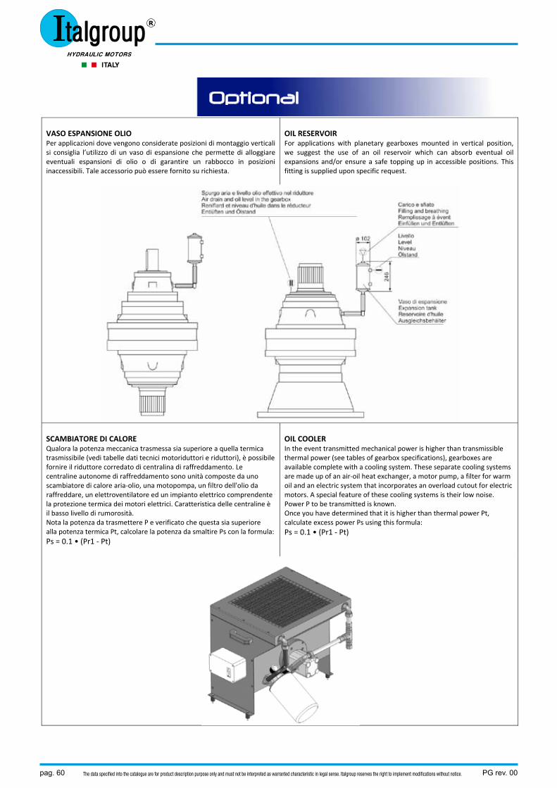
pag. 60 PG rev. 00The data specified into the catalogue are for product description purpose only and must not be interpreted as warranted characteristic in legal sense. Italgroup reserves the right to implement modifications without notice.
VASO ESPANSIONE OLIO Per applicazioni dove vengono considerate posizioni di montaggio verticali si consiglia l’utilizzo di un vaso di espansione che permette di alloggiare eventuali espansioni di olio o di garantire un rabbocco in posizioni inaccessibili. Tale accessorio può essere fornito su richiesta.
OIL RESERVOIR For applications with planetary gearboxes mounted in vertical position, we suggest the use of an oil reservoir which can absorb eventual oil expansions and/or ensure a safe topping up in accessible positions. This fitting is supplied upon specific request.
SCAMBIATORE DI CALORE Qualora la potenza meccanica trasmessa sia superiore a quella termica trasmissibile (vedi tabelle dati tecnici motoriduttori e riduttori), è possibile fornire il riduttore corredato di centralina di raffreddamento. Le centraline autonome di raffreddamento sono unità composte da uno scambiatore di calore aria‐olio, una motopompa, un filtro dell'olio da raffreddare, un elettroventilatore ed un impianto elettrico comprendente la protezione termica dei motori elettrici. Caratteristica delle centraline è il basso livello di rumorosità. Nota la potenza da trasmettere P e verificato che questa sia superiore alla potenza termica Pt, calcolare la potenza da smaltire Ps con la formula: Ps = 0.1 • (Pr1 ‐ Pt)
OIL COOLER In the event transmitted mechanical power is higher than transmissible thermal power (see tables of gearbox specifications), gearboxes are available complete with a cooling system. These separate cooling systems are made up of an air‐oil heat exchanger, a motor pump, a filter for warm oil and an electric system that incorporates an overload cutout for electric motors. A special feature of these cooling systems is their low noise. Power P to be transmitted is known. Once you have determined that it is higher than thermal power Pt, calculate excess power Ps using this formula: Ps = 0.1 • (Pr1 ‐ Pt)
Optional


ITALGROUP srlVIA PACINOTTI, 20/22 - 41013 GAGGIO DI PIANOCASTELFRANCO EMILIA - MODENA - ITALYTel. +39 059 924257 - Fax +39 059 920113E-mail: [email protected] Site: www.italgroup.eu
salvi
oli.i
t Co
d. P
G re
v. 00
![technology made in Italy - ATTI srl · T2 ISO [ Nm ] - Coppia di uscita nominale secondo ISO 6336 n2 eqv [ rpm ] - Velocità equivalente risultante dalle singole velocità del ciclo](https://static.documenti.site/doc/80x56/5c6a01b109d3f20c178bf6d8/technology-made-in-italy-atti-srl-t2-iso-nm-coppia-di-uscita-nominale.jpg)


![RG - TC service · FS Fattore di shock i Rapporto di riduzione (valori finiti) J1 ... Coppia nominale del riduttore secondo ISO 6336 (S1 - funzionamento continuo) T2max [Nm] Coppia](https://static.documenti.site/doc/80x56/5c6a01b109d3f20c178bf6ce/rg-tc-fs-fattore-di-shock-i-rapporto-di-riduzione-valori-finiti-j1-coppia.jpg)


![technology made in Italy - TC service · T2 ISO [ Nm ] - Coppia di uscita nominale secondo ISO 6336 n2 eqv [ rpm ] - Velocità equivalente risultante dalle singole velocità del ciclo](https://static.documenti.site/doc/80x56/5c6a01b109d3f20c178bf6cc/technology-made-in-italy-tc-t2-iso-nm-coppia-di-uscita-nominale-secondo.jpg)


