52
Riduttori e Motoriduttori vite senza fine Worm gear units

Riduttor i e Motor iduttor i v i te senza f ineWorm gear un i ts


5
Indice Index
6 | Il Gruppo
9 | La Mission
10 | Installazione
11 | Applicazioni critiche
12 | Lubrifi cazione
14 | Fattore di servizio
SERIE CRV-CMRV
16 | Versioni
17 | Posizioni di montaggio
18 | Caratteristiche principali
19 | Gamma di riduttori
20 | Dimensione e ingombri riduttori grandezze 030-150
21 | Schema fl ange di uscita
22 | Prestazioni
SERIE CRV-E/CMRV-E
25 | Vite senza fi ne a doppia sporgenza
26 | Predisposizioni attacco motore
27 | Braccio di reazione
27 | Dimensione alberi di uscita semplice, doppio
SERIE RIDUTTORI COMBINATI CRR-CMRR
28 | Dimensione e ingombri riduttori
29 | Posizioni di montaggio
30 | Prestazioni
RIDUTTORI CON PRECOPPIA CMRP
32 | Combinazioni
33 | Dimensione e ingombri riduttori
34 | Dimensione e ingombri riduttori PR - Posizioni di montaggio
35 | Prestazioni
SERIE CRB-CMRB
37 | Caratteristiche principali
38 | Gamma di riduttori
39 | Dimensione e ingombri riduttori
SERIE CRB-CMRB CON PIEDI
40 | Dimensione e ingombri riduttori
41 | Prestazioni
42 | Dimensione accessori
43 | Predisposizione attacco motore
VARIATORI SERIE CV
45 | Designazione
46 | Dimensione - Caratteristiche - Lubrifi cazione
47 | Uso e Manutenzione - Lista parti di ricambio
The Group
The Mission
Installation
Critical applications
Lubrication
Service factor
CRV AND CMRV SERIES
Versions
Mounting positions
Main features
Range
Reducer sizes 030-150 overall dimensions
Output fl ange position scheme
Performances
CRV-E/CMRV-E SERIES
Double worm shaft
Motor fl ange adapters
Torque arm
Output shaft dimensions: single, double
CRR-CMRR COMBINED REDUCER SERIES
Reducers overall dimensions
Mounting positions
Performances
HELICAL-WORM REDUCERS CMRP
Combinations
Reducers overall dimensions
PR reducers overall dimensions - Mounting positions
Performances
CRB-CMRB SERIES
Main features
Range
Reducers overall dimensions
CRB-CMRB WITH FEET SERIES
Reducers overall dimensions
Performances
Accessories dimensions
Motor adapters
SPEED VARIATORS CV SERIES
Designation
Dimensions - Main features - Lubrication
Use and Maintenance - Spare part list

6
Il Gruppo The Group
CMR, nasce a Scandiano (RE) nel 1990, come azienda
produttrice in conto terzi di pulegge e alberi da smalteria
(settore ceramico). Grazie a nuovi investimenti,
soprattutto all’estero, attua in pochi anni una rapida
crescita e diversifi cazione della propria attività.
Tra il 1995 e il 1996 si trasferisce nell’attuale sede di
Borzano di Albinea (RE). Inizia così una profonda
trasformazione aziendale che, ad oggi, conta 5
stabilimenti produttivi (Italia, Cina) attraverso i quali
CMR è in grado di fornire al cliente alta tecnologia a
costi contenuti, sfruttando sinergie internazionali.
Il know-how raggiunto, permette di offrire al Cliente
non solo un servizio completo, dalla progettazione
personalizzata del prodotto, sino alla sua completa
realizzazione, ma anche un supporto commerciale-
tecnico in grado di rispondere a tutte le esigenze in
tempo reale.
Grazie alla elevata professionalità ed ai processi di
produzione tecnologicamente avanzati, CMR diventa
un vero e proprio partner tecnologico per tutti i suoi
Clienti nell’ottica di un elevato rapporto qualità/prezzo.
CMR was founded in Scandiano (RE) in 1990 as a
custom manufacturer of pulleys and shafts for glazers
(ceramic tile industry). Thanks to new investments,
mainly abroad, the company rapidly developed and
diversifi ed its activity in just a few years.
Between 1995 and 1996 the company moved to its
current location in Borzano, Albinea (RE). Over the
years CMR has undergone a profound transformation
and today boasts 5 production plants in Italy, China.
Thanks to these plants, and by taking advantage
of international synergies, CMR is able to offer its
customers high-level technology at a reasonable cost.
The level of know-how attained allows CMR to offer
its customers a complete service from custom design
to production, as well as provide technical and
commercial assistance to satisfy customer needs in
real time.
Thanks to the high level of professionalism and to the
technologically advanced production processes, CMR
is a true technological partner for its customers, with
an excellent quality-price ratio.


9
La Mission The Mission
Il GRUPPO CMR è da sempre sensibile alle tematiche
di industrializzazione ed al contenimento dei costi
di produzione, obbiettivo perseguibile attraverso
l’identifi cazione di ciò che CMR defi nisce come propri
principi guida:
Responsabilità verso i Clienti: Fidelizzare il Cliente con
un impegno costante in attività di ricerca-sviluppo,
fornendo prodotti e servizi in grado di soddisfare le
aspettative del Cliente garantendo la qualità del prodotto.
Responsabilità verso i dipendenti: Valorizzare le
proprie risorse umane, favorendo la crescita delle
diverse competenze, stimolando lo spirito aziendale,
la formazione/aggiornamento attraverso lo sviluppo
di condizioni lavorative non discriminanti, nel rispetto
dei requisiti di qualità e sicurezza.
Responsabilità verso la società: Gestire il business con
grande senso di responsabilità sociale, in conformità
alle leggi dei diversi paesi in cui opera, nel rispetto
della protezione dei diritti umani riconosciuti in campo
internazionale.
Piano strategico aziendale: Obiettivo aziendale è il
rafforzamento nei mercati internazionali attraverso
il potenziamento della rete commerciale in Italia e
all’Estero, grazie al lancio di nuovi prodotti con marchio
CMR, tra i quali fi gurano i riduttori a vite senza fi ne.
The CMR GROUP has always been sensitive to
industrialisation and cost containment issues, an
objective refl ected in the guiding principles of CMR:
Responsibility towards its customers: to build
customer loyalty with a constant commitment to
research and development, supplying products
and services that satisfy customer expectations
guaranteeing product quality.
Responsibility towards its employees: to improve
human resource skills by encouraging the
development of expertise, stimulating corporate
spirit, providing training and refresher courses, and
developing non-discriminatory working conditions,
all in compliance with the quality and safety
requirements in force.
Responsibility towards society: to manage the
business with a great sense of social responsibility in
accordance with the laws of those countries in which
CMR operates, whilst respecting international human
rights.
Corporate strategic plan: The company’s objective
is to reinforce its position on international markets
through the development of the commercial network
in Italy and abroad, thanks to the launch of new CMR
branded products including worm reducers.

10
Installazione Installation
Per l’installazione del riduttore è consigliabile seguire
le indicazioni elencate:
Il fi ssaggio sulla macchina deve essere stabile per evitare
vibrazioni.
Prima del montaggio del gruppo sulla macchina verifi care il
corretto senso di rotazione dell’albero di uscita del riduttore.
Quando possibile proteggere il riduttore dall’irraggiamento solare
e dalle intemperie.
In caso di lunghi periodi di stoccaggio (4/6 mesi) se l’anello di
tenuta non è immerso nel lubrifi cante contenuto all’interno
del gruppo si consiglia la sua sostituzione in quanto la gomma
potrebbe essersi incollata all’albero o aver perso le caratteristiche
di elasticità necessarie al corretto funzionamento.
Garantire un corretto raffreddamento del motore assicurando un
buon passaggio d’aria dal lato della ventola.
Nel caso di temperature ambiente <-5°C o >+40°C contattare il ns.
Servizio Tecnico.
Per evitare grippaggi o ossidazioni lubrifi care le superfi ci a contatto.
Il montaggio dei vari organi (ruote dentate, pulegge, giunti, alberi,
ecc.) sugli alberi pieni o cavi deve essere eseguito utilizzando
appositi fori fi lettati o altri sistemi che garantiscano una corretta
operazione senza rischiare il danneggiamento dei cuscinetti o
delle parti esterne dei gruppi.
Controllare il corretto livello del lubrifi cante tramite, quando
prevista, l’apposita spia.
Per i gruppi provvisti di tappi per olio sostituire il tappo chiuso
utilizzato per la spedizione con l’apposito tappo di sfi ato.
La verniciatura non deve interessare le parti in gomma e i fori
presenti sui tappi di sfi ato, quando presenti.
Quando sotto alla motorizzazione sono presenti organi, cose o
materiali danneggiabili dall’eventuale fuoriuscita, anche limitata,
di olio è opportuno prevedere un’apposita protezione.
La messa in funzione deve avvenire in maniera graduale, evitando
l’applicazione immediata del carico massimo.
The here below recommendations must be followed in
order to get a correct reducer installation:
The fastening on the machine must be stable to avoid any
vibrations.
The correct direction of rotation of the reducer before fi xing it on
the machine must be checked.
Whenever possible, it is necessary to protect the reducer against
solar radiation and bad weather.
In case of long storage periods (4/6 months), if the oil seal is not
immersed in the lubricant inside the unit, it is recommended to
replace the seal since the rubber might have stuck to the shaft or
have lost the necessary elasticity to properly function.
It is necessary to ensure a correct cooling of the motor by assuring
a good passage of air from the fan side.
In case of ambient temperature <-5°C o >+40°C call our Technical
Service.
It is important to lubricate the surfaces in contact to avoid any
seizures or oxidations.
The coupling accessories (pulleys, gear wheels, couplings, shafts
etc.) must be fi xed on the solid or hollow shafts by using specifi c
threaded holes or other systems that ensure a correct operation
without risking to damage the bearings or the external parts of
the reducer.
The correct level of the lubricant (through the indicator if there is
one) has to be double checked.
For units equipped with oil plugs, replace the closed plug used for
the transport with the special breather plug.
No paintings are allowed over the rubber parts or over the holes
on the breather plugs if any.
When there are parts, objects or materials under the reducer
unit, that can be damaged by even limited oil leakage, a special
protection should be fi tted.
First start-up must take place gradually, without immediately
applying the maximum load.
>
>
>
>
>
>
>
>
>
>
>
>
>
>
>
>
>
>
>
>
>
>
>
>
>
>
11
Applicazioni critiche Critical applications
Le prestazioni indicate a catalogo corrispondono alla
posizione B3 o similari, quando cioè il primo stadio
non è interamente immerso in olio. Per situazioni di
piazzamento diverse e/o velocità di ingresso particolari
attenersi alle tabelle che evidenziano situazioni
critiche diverse per ciascuna taglia di riduttore.
Occorre anche tenere nella giusta considerazione
e valutare attentamente le seguenti applicazioni
consultando il ns. servizio Tecnico:
Utilizzo in servizi che potrebbero risultare pericolosi per l’uomo in
caso di rottura del riduttore.
Utilizzo come moltiplicatore.
Utilizzo come argano di sollevamento.
Applicazioni con inerzie particolarmente elevate.
Applicazioni con elevate sollecitazioni dinamiche sulla cassa del
riduttore.
Utilizzo in ambiente con presenza di aggressivi chimici.
Utilizzo in ambiente con T° inferiore a -5°C o superiore a +40°C.
Utilizzo in ambiente con pressione diversa da quella atmosferica.
Utilizzo in ambiente salmastro.
Posizioni di piazzamento non previste a catalogo.
Utilizzo in ambiente radioattivo.
Evitare applicazioni dove è prevista l’immersione,
anche parziale, del riduttore. La coppia massima (*)
sopportabile dal riduttore non deve superare il doppio
della coppia nominale (f.s.=1) riportata nelle tabelle
delle prestazioni.
(*) intesa come sovraccarico istantaneo dovuto ad avviamenti a
pieno carico, frenature, urti ed altre cause soprattutto dinamiche.
The performances given in this catalogue correspond
to B3 mounting scheme or similar, when the first stage
is not entirely immersed in oil. For other mounting
positions and/or particular input speeds, refer to the
tables which highlights different critical situations for
each size of reducer.
It is also necessary to take into due consideration and
carefully assess, the following applications by calling
our Technical Service:
Use in applications which could be hazardous for the user in case
of reducer failure.
Use as a speed increasing unit.
Use as a lifting winch.
Applications with great inertia.
Applications with high dynamic strain on the case of the reducer.
Use in chemically aggressive environments.
Use in sites with temperatures under -5°C or over 40°C.
Use in environment pressures other than the atmospheric
pressure.
Use in a salty environment.
Mounting positions not envisaged in the catalogue.
Use in radioactive environments.
Avoid any applications where even a partial immersion
of the reducer is required. The maximum torque (*) that
the reducer can support must not exceed two times
the nominal torque (f.s.=1) stated in the performance
tables.
(*) intended for momentary overloads due to starting at full load,
braking, shocks or other causes, in particular dynamic causes.
>
>
>
>
>
>
>
>
>
>
>
>
>
>
>
>
>
>
>
>
>

12
Lubrifi cazione Lubrication
I riduttori delle gr. 025-030-040-050-063-075 vengono forniti
lubrifi cati a vita, completi di olio a base sintetica ISO VG320.
I riduttori delle gr. 025-030-040-050-063 possono essere montati
in tutte le posizioni di piazzamento previste a catalogo.
I riduttori gr. 090-110-130-150 vengono forniti completi di, olio
lubrifi cante a base minerale, ISO VG460.
Per le gr. 075-090-110-130-150 occorre sempre specifi care la
posizione di piazzamento, se questo non avviene i riduttori
vengono forniti con le q.tà di olio relative alla pos. B3.
Nei riduttori gr. 090-110-130-150 l’olio deve essere completamente
sostituito dopo le prime 400 ore di funzionamento, in seguito va
sostituito ogni 4000 ore di funzionamento.
Occorre controllare regolarmente il livello dell’olio di lubrifi cazione
e se necessario rabboccarlo per mantenerlo al livello corretto.
Solo i riduttori gr. 090-110-130-150 sono provvisti dei tappi di
carico/sfi ato, livello (escluso 090) e scarico olio; si raccomanda,
effettuata l’installazione, di sostituire il tappo chiuso utilizzato per
il trasporto, con il tappo di sfi ato allegato al gruppo.
Nei casi con temperature ambiente <-5°C oppure
>+40°C contattare il ns. Servizio Tecnico. Per condizioni
di funzionamento con temperature inferiori a 0°C
occorre considerare quanto segue:
1 - I motori devono essere idonei al funzionamento con temperatura
ambiente prevista.
2 - La potenza del motore elettrico deve essere adeguata al
superamento delle maggiori coppie di avviamento richieste.
3 - Nel caso di riduttori con cassa in ghisa prestare attenzione
ai carichi d’urto in quanto la ghisa può presentare problemi di
fragilità a temperature inferiori a -15°C.
4 - Durante le prime fasi di servizio possono insorgere problemi di
lubrifi cazione causa l’elevata viscosità che assume l’olio e quindi è
opportuno procedere ad alcuni minuti di rotazione a “vuoto”.
The reducer sizes 025-030-040-050-063-075 are supplied with
lifetime lubricated with synthetic oil ISO VG320.
The reducer sizes 025-030-040-050-063 could be fi tted in any
mounting position indicated in our catalogue.
The reducer sizes 090-110-130-150 are supplied complete with
mineral oil lubricant, ISO VG460.
For sizes 075-090-110-130-150 it is always necessary to specify the
mounting position, otherwise the reducers are supplied with the
quantity of oil related to pos. B3.
The lubricating oil in the reducer sizes 090-110-130-150 must be
replaced after the fi rst 400 working hours, afterwards it must be
replaced every 4,000 working hours.
Lubricating oil level must be regularly checked and if necessary oil
must be added to keep the correct oil level.
Only the reducer sizes 090-110-130-150 are fi tted with breather,
level (exluded 090) and oil drainage plugs. After the installation it
is necessary to replace the closed plug used for transport with the
breather plug supplied with the unit.
In case of ambient temperatures <-5°C or >+40°C, call
our Technical Service. For operating enviroiments with
temperatures under 0°C it is necessary to consider the
following precautions:
1 - The motors must be suitable for operation at the envisaged
ambient temperature.
2 - The power of the electric motor must be adequate for exceeding
the higher starting torques required.
3 - In case of reducers with cast-iron case, pay attention to the
impact loads since cast iron may have problems of fragility at
temperatures under -15°C.
4 - During the early stages of service, problems of lubrication may
arise due to the high level of viscosity taken on by the oil and so it
is advisable to have a few minutes of rotation without load.
>
>
>
>
>
>
>
>
>
>
>
>
>
>
13
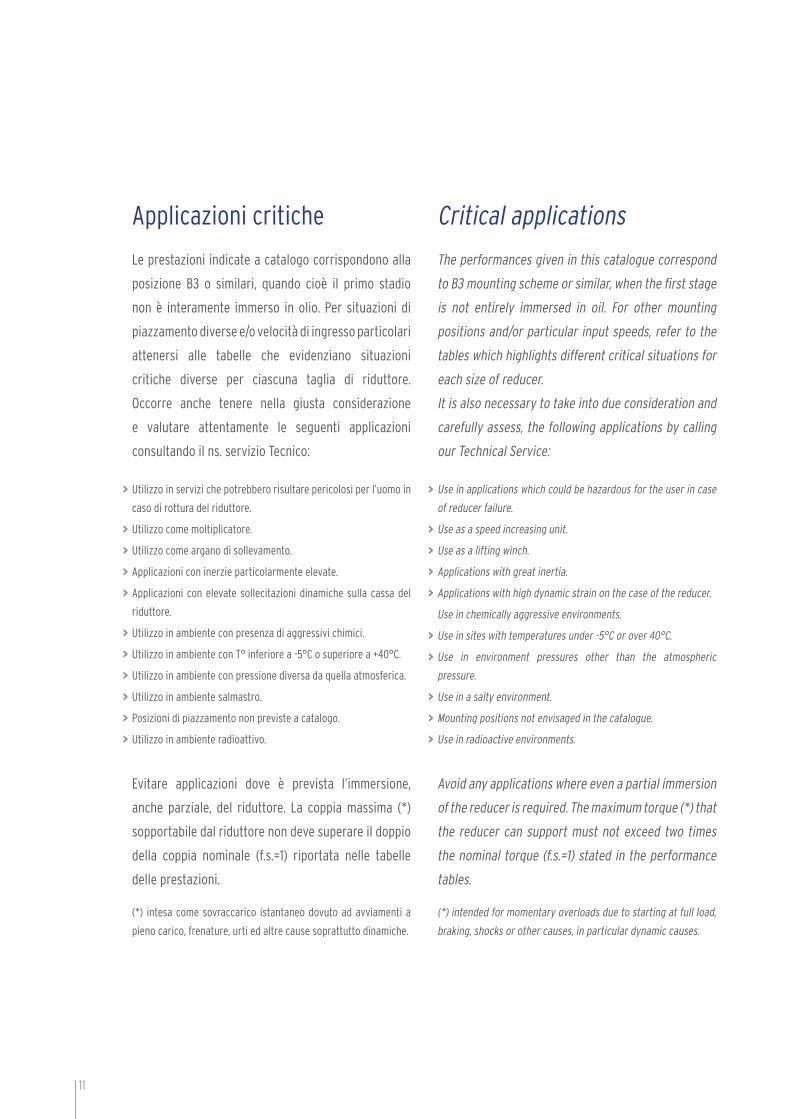
Quantità olio (in litri)Oil quantity (in liters)
TagliaSize 25 30 40 50 63 75 90 110 130 150
Posizione - Position B3 0.02 0.04 0.08 0.15 0.3 0.55 1 3 4.5 7
Posizione - Position B8 0.02 0.04 0.08 0.15 0.3 0.55 1 2.2 3.3 5.1
Posizione - Position B6-B7 0.02 0.04 0.08 0.15 0.3 0.55 1 2.5 3.5 5.4
Posizione - Position V5 0.02 0.04 0.08 0.15 0.3 0.55 1 3 4.5 7
Posizione - Position V6 0.02 0.04 0.08 0.15 0.3 0.55 1 2.2 3.3 5.1
Quantità olio (in litri)Oil quantity (in liters)
Precoppie PR 63 71 80 90
Tutte le posizioniAll positions
0.05 0.07 0.15 0.16
Nota: olio minerale ISO VG 460
Note: mineral oil ISO VG 460
>
>

14
Fattore di servizio Service factor
Il fattore di servizio f.s. dipende dalle condizioni di
funzionamento sottoposte ad un riduttore.
Per una corretta selezione del fattore di servizio più
adeguato occorre considerare i seguenti parametri:
tipo del carico della macchina azionata: A-B-C
frequenza di avviamento: avv/ora
durata di funzionamento giornaliero: ore/giorno (Ø)
A – Coclee per materiali leggeri, linee di montaggio, ventole, nastri
trasportatori per materiali leggeri, elevatori, macchine pulitrici,
piccoli agitatori, macchine riempitrici, macchine per il controllo.
B – Apparecchi per l’alimentazione delle macchine per il legno,
dispositivi di avvolgimento, equilibratrici, agitatori medi e
mescolatori, montacarichi, fi lettatrici, nastri trasportatori per
materiali pesanti, porte scorrevoli, verricelli, raschiatore di
concime, betoniere, macchine per l’imballaggio, frese, piegatrici,
meccanismi per il movimento delle gru, pompe a ingranaggi.
C – Presse, cesoie, agitatori per materiali pesanti, centrifughe,
supporti rotanti, verricelli per ascensori per materiali pesanti,
frantoi da pietre, torni per la rettifi ca, elevatori a tazze, perforatrici,
presse ad eccentrico, mulini a martello, piegatrici, barilatrici,
vibratori, tranciatrici, tavole rotanti.
The service factor (f.s.) depends on the operating
conditions the reducer is subject to.
To correctly select the most suitable service factor, it
is necessary to consider the following parameters:
type of load of the application: A-B-C
start-up frequency: starts/hour
length of daily operating time: hours/day (D)
A – Screw feeders for light materials, assembly lines, fans,
conveyor belts for light materials, lifts, cleaning machines, small
mixers, fi llers, control machines.
B – Woodworking machine feeders, winding devices, balancing
machines, medium mixers, goods lifts, threading machines,
conveyor belts for heavy materials, sliding doors, winches, fertilizer
scrapers, concrete mixers, packing machines, milling cutters,
folding machines, crane mechanisms, gear pumps.
C – Presses, shears, mixers for heavy materials, centrifuges,
rotating supports, winches and lifts for heavy materials, stone
mills, grinding lathes, bucket elevators, drilling machines, cam
presses, hammer mills, folding machines, tumbling barrels,
vibrators, shredders, turntables.
>
>
>
>
>
>

15
Fattore di servizioService Factor
24 16 8 2Ore | GiornoHours | Day
2.3 2 1.8 1.6
2.2 1.9 1.7 1.5
2.1 1.8 1.6 1.4
2 1.7 1.5 1.3
1.9 1.6 1.4 1.2
1.8 1.5 1.3 1.1
1.7 1.4 1.2 1
1.6 1.3 1.1 0.9
1.5 1.2 1 0.8
F.S. 5 10 20 30 40 50 60 70 80 90 100
Avviamenti | Ora Starts | Hour
C
B
A
16
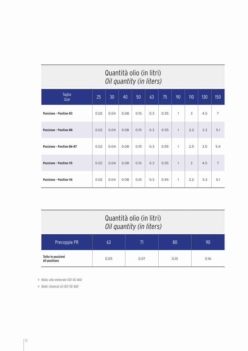
Versioni | Versions
CRV
CMRV
CMRV-FL
CRV-E
CMRV-E
CMRV-F
Serie CRV-CMRV | CRV-CMRV SeriesCaratteristiche principali | Main features

17
CMRV-B3 CMRV-B6 CMRV-V5
CMRV-B8 CMRV-B7 CMRV-V6
Posizione Morsettiera | Terminal Board Position
Posizioni di montaggio | Mounting positions
Per le posizioni di montaggio verticali B6, B7, V5 e V6, verifi care quanto
detto nelle applicazioni critiche.
Se non diversamente specifi cato le posizioni standard sono B3/A.
Per le posizioni di montaggio non previste occorre rivolgersi al ns. Servizio Tecnico.
For vertical position, B6, B7, V5 e V6, check with critical application.
Unless otherwise specifi ed, the standard positions are B3/A.
For positions not envisaged, it is necessary to call our Technical Service.
>
>
>
>
>
>
A
B
DS
A
A
AA
AA
A
A
18
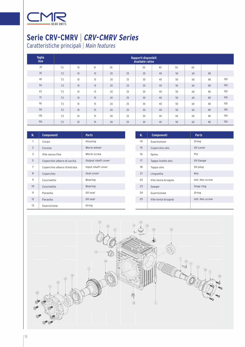
Serie CRV-CMRV | CRV-CMRV SeriesCaratteristiche principali | Main features
TagliaSize
Rapporti disponibiliAvailable ratios
25 7,5 10 15 20 30 40 50 60
30 7,5 10 15 20 25 30 40 50 60 80
40 7,5 10 15 20 25 30 40 50 60 80 100
50 7,5 10 15 20 25 30 40 50 60 80 100
63 7,5 10 15 20 25 30 40 50 60 80 100
75 7,5 10 15 20 25 30 40 50 60 80 100
90 7,5 10 15 20 25 30 40 50 60 80 100
110 7,5 10 15 20 25 30 40 50 60 80 100
130 7,5 10 15 20 25 30 40 50 60 80 100
150 7,5 10 15 20 25 30 40 50 60 80 100
N. Componenti Parts
14 Guarnizione Oring
15 Coperchio olio Oil cover
16 Spina Pin
17 Tappo livello olio Oil Gauge
18 Tappo olio Oil plug
21 Linguetta Key
22 Vite testa brugola Intl. Hex screw
23 Seeger Snap ring
24 Guarnizione Oring
25 Vite testa brugola Intl. Hex screw
N. Componenti Parts
1 Corpo Housing
2 Corona Worm wheel
3 Vite senza fi ne Worm screw
5 Coperchio albero di uscita Output shaft cover
7 Coperchio albero d'entrata Input shaft cover
8 Coperchio Seal cover
9 Cuscinetto Bearing
10 Cuscinetto Bearing
11 Paraolio Oil seal
12 Paraolio Oil seal
13 Guarnizione Oring

19
CodiceCode
DescrizioneDescription
CMRV Sigla prodotto CMRV: predisposto attacco motore, CRV: con albero veloce sporgenteProduct identification CMRV: motor ready, CRV: with input solid shaft
63 GrandezzaSize
40 Rapporto di riduzioneReduction ratio
E E: per vite a doppia sporgenza, senza sigla per vite standardE: for double extension worm shaft, “no mark”: for standard worm screw
F1 Tipo di flangia di uscita, senza sigla flangia assenteOutput flange type: “no mark”: no flange
71B5 Tipo di motore applicabileSuitable type of motor
Gamma di riduttori CRV e CMRV
CARATTERISTICHE DEI PRODOTTI:
1 - La carcassa dei riduttori gr. 025 - 030 - 040 - 050 - 063 - 075 - 090 è in lega di alluminio, impregnato dopo lavorazione.
2 - La carcassa dei riduttori gr. 110 - 130 - 150 viene realizzata in ghisa.
3 - Componenti interni realizzati con materiali selezionati e lavorazioni controllate.
4 - Elevata coppia trasmissibile.
5 - Notevole affidabilità e funzionamento estremamente silenzioso.
CRV and CMRV range
FEATURES OF THE PRODUCTS:
1 - The case of the reducer sizes 025 - 030 - 040 - 050 - 063 - 075 - 090 is aluminium made, impregnated after machining.
2 - The case of the reducer sizes 110-130 and 150 is cast iron made.
3 - Internal parts are made with selected materials and highly controlled machinings.
4 - High transmissible torque.
5 - High reliability and extremely noiseless operation.

20
Serie CRV-CMRV | CRV-CMRV SeriesDimensione e ingombri riduttori grandezze 030-150 | Reducer sizes 030-150 overall dimensions
CRV CMRVF
CMRV
F1, FL1, FB1 F2, FL2, FB2
Schema fl ange di uscita | Output fl ange position scheme
G2 B
ØD2
Ø O
XE
α
t1
b1
ØXQØXL
ØXO
ØXN
α1
ØXP
XA
XB
XC
C
HR Q
VI
S
ØL
AE
H G
G1
T T
ØD1
t
b
G
N N
ØN
MXF
1
1 1
G2 BØ
D2
Ø O
XE
α
t1
b1
ØXQØXL
ØXO
ØXN
α1
ØXP
XA
XB
XC
C
HR Q
VI
S
ØL
AE
H G
G1
T T
ØD1
t
b
G
N N
ØN
MXF
1
1 1

21
TagliaSize
A B C D1(H7) D2(J6) E F G G1 G2 H I L M N(h8) N1 O P Q R S T V X
030 54 20 97 14 9 80 32 55 63 51 40 30 65 56 55 29 6,5 75 44 57 5,5 21 27 44
040 70 23 121,5 18(19) 11 100 43 70 78 60 50 40 75 71 60 36,5 6,5 87 55 71,5 6,5 26 35 60
050 80 30 144 25(24) 14 120 49 80 92 74 60 50 85 85 70 43,5 8,5 100 64 84 7 30 40 70
063 100 40 174 25(28) 19 144 67 95 112 90 72 63 95 103 80 53 8,5 110 80 102 8 36 50 85
075 120 50 205 28(35) 24 172 72 112,5 120 105 86 75 115 112 95 57 11 140 93 119 10 40 60 90
090 140 50 238 35(38) 24 208 74 129,5 140 125 103 90 130 130 110 67 13 160 102 135 11 45 70 100
110 170 60 295 42 28 252,5 / 160 155 142 127,5 110 165 144 130 74 14 200 125 167,5 14 50 85 115
130 200 80 335 45 30 292,5 / 180 170 162 147,5 130 215 155 180 81 16 250 140 187,5 15 60 100 120
150 240 80 400 50 35 340 / 210 200 192 170 150 215 185 180 96 18 250 180 230 18 72,5 120 145
Dimensione e ingombri riduttori grandezze 030-150 | Reducer sizes 030-150 overall dimensions
TagliaSize
XA XB XCXE α b t b1 t1 f kg
F FB FL FE FD F FB FL FE FD F FB FL FE FD
030 54,5 / / / / 6 / / / / 4 / / / / M6x11 (n.4) 0° 5 16,3 3 10,2 / 1,2
040 67 76,5 97 / / 7 9 7 / / 4 5 4 / / M6x8 (n.4) 45° 6(6) 20,8(21,8) 4 12,5 / 2,3
050 90 87,5 120 / / 9 10 9 / / 5 5 5 / / M8x10 (n.4) 45° 8(8) 28,3(27,3) 5 16 M6 3,5
063 82 99 112 80,5 / 10 11 10 13,5 / 6 5 6 6 / M8x14 (n.8) 45° 8(8) 28,3(31,3) 6 21,5 M6 6,2
075 111 / 90 / / 13 / 13 / / 6 / 6 / / M8x14 (n.8) 45° 8(10) 31,3(38,3) 8 27 M8 9
090 111 110 122 / 151 13 17 18 / 13 6 6 6 / 6 M10x18 (n.8) 45° 10(10) 38,3(41,3) 8 27 M8 13
110 131 / / / / 15 / / / / 6 / / / / M10x18 (n.8) 45° 12 45,3 8 31 M10 35
130 140 / / / / 15 / / / / 6 / / / / M12x21 (n.8) 45° 14 48,8 8 33 M10 48
150 155 / / / / 15 / / / / 6 / / / / M12x21 (n.8) 45° 14 54 10 38 M12 84
TagliaSize
Ø XP Ø XL Ø XOα
Ø XN (H8) XQ
F FB FL FE FD F FB FL FE FD F FB FL FE FD F FB FL FE FD F FB FL FE FD
030 80 / / / / 68 / / / / 6,5(n.4) / / / / 45° 50 / / / / 70 / / / /
040 110 140 110 / / 80/87 115 80/87 / / 9(n.4) 9,5(n.4) 9(n.4) / / 45° 60 95 60 / / 95 / 95 / /
050 125 160 125 / / 90 130 90 / / 11(n.4) 9,5(n.4) 11(n.4) / / 45° 70 110 70 / / 110 / 110 / /
063 180 200 180 160 / 150 165 150 130 / 11(n.4) 11(n.4) 11(n.4) 11(n.4) / 45° 115 130 115 110 / 142 / 142 / /
075 200 / 160 / / 165 / 130 / / 14(n.4) / 14(n.4) / / 45° 130 / 110 / / 170 / 160 / /
090 210 200 250 / 210 175 165 215 / 175 14(n.4) 11(n.4) 14(n.4) / 14(n.4) 45° 152 130 180 / 152 200 / 230 / /
110 280 / / / / 230 / / / / 14(n.8) / / / / 45° 170 / / / / 260 / / / /
130 320 / / / / 255 / / / / 16(n.8) / / / / 22,5° 180 / / / / 290 / / / /
150 320 / / / / 255 / / / / 16(n.8) / / / / 22,5° 180 / / / / 290 / / / /

22
TagliaSize
RapportoRatio
Vel.in uscita Output speed
n2 (rpm)
Motore / Motor ( 4 poli/poles , 1400rpm )
Taglia / Size P1 (kW) M2 (Nm) f.s. Pn (Kw) Mn (Nm) η %
CMRV 025
7,5 186,7 56B4 0,09 3,9 2,8 0,25 11 85
10 140,0 56B4 0,09 5,1 2,4 0,22 12 83
15 93,3 56B4 0,09 7,3 1,6 0,14 11,7 79
20 70,0 56B4 0,09 9,2 1,3 0,12 12 75
30 46,7 56B4 0,09 12 1,1 0,1 13 65
40 35,0 56B4 0,09 15 0,9 0,08 13,5 61
50 28,0 56A4 0,06 12 0,9 0,05 11 59
60 23,3 56A4 0,06 14 0,7 0,04 10 57
CMRV 030
7,5 186,7 63C4 0,25 11 1,7 0,42 19 89
10 140,0 63C4 0,25 14 1,3 0,33 18 80
15 93,3 63C4 0,25 19 0,9 0,22 17 76
20 70,0 63C4 0,25 25 0,7 0,18 17,6 73
25 56,0 63B4 0,18 21 1,0 0,18 21 68
30 46,7 63B4 0,18 24 0,8 0,14 19 65
40 35,0 63A4 0,12 19 0,9 0,11 17 58
50 28,0 63A4 0,12 23 0,8 0,1 18,4 56
60 23,3 56B4 0,09 19 0,9 0,08 17 52
80 17,5 56A4 0,06 14 0,9 0,05 12,6 43
CMRV 040
7,5 186,7 71C4 0,55 24 1,6 0,88 38,4 85
10 140,0 71C4 0,55 32 1,3 0,72 41,6 85
15 93,3 71C4 0,55 46 0,9 0,5 41,4 82
20 70,0 71B4 0,37 39 1,0 0,37 39 77
25 56,0 71B4 0,37 47 0,8 0,3 37,6 74
30 46,7 71B4 0,37 53 0,8 0,3 42,4 70
40 35,0 63C4 0,25 44 0,9 0,23 39,6 65
50 28,0 63C4 0,25 53 0,7 0,18 37,6 63
60 23,3 63B4 0,18 43 0,8 0,14 34,4 58
80 17,5 63A4 0,12 34 1,0 0,12 34 52
100 14,0 63A4 0,12 38 0,8 0,1 30,4 46
CMRV 050
7,5 186,7 80C4 1,10 49 1,4 1,56 70 87
10 140,0 80C4 1,10 65 1,1 1,2 70 86
15 93,3 80C4 1,10 92 0,8 0,92 77 82
20 70,0 80B4 0,75 81 0,9 0,68 73 79
25 56,0 80A4 0,55 71 1,0 0,55 71 76
30 46,7 80A4 0,55 81 1,0 0,55 81 72
40 35,0 71B4 0,37 68 1,1 0,41 75 67
50 28,0 71B4 0,37 80 0,9 0,33 72 63
60 23,3 71B4 0,37 89 0,8 0,3 71 59
80 17,5 71A4 0,25 72 0,9 0,23 65 53
100 14,0 63B4 0,18 60 0,9 0,16 54 49
CMRV 063
7,5 186,7 90LB4 2,20 99 1,3 2,76 125 88
10 140,0 90LB4 2,20 130 1,0 2,21 131 87
15 93,3 90L4 1,50 156 0,9 1,66 140 83
20 70,0 90L4 1,50 166 0,8 1,2 133 81
25 56,0 90S4 1,10 146 0,9 0,99 131 78
30 46,7 90S4 1,10 167 1,0 1,1 167 74
40 35,0 80B4 0,75 143 1,0 0,74 141 70
50 28,0 80A4 0,55 124 1,1 0,61 136 66
60 23,3 80A4 0,55 140 0,9 0,5 126 62
80 17,5 71B4 0,37 115 1,1 0,41 127 57
100 14,0 71B4 0,37 129 0,9 0,33 116 51
LEGENDA / LEGEND:
Motore / Motor Taglia motore max ammessa / Max motor size P1 (kW) Potenza motore / Motor power M2 (Nm) Coppia in uscita / Output torque f.s. Fattore di servizio con motore applicato / Service factor with applied motor
Pn (kW) Potenza nominale a 1400rpm in ingresso / Nominal input power at 1400rpmMn (Nm) Coppia nominale in uscita con 1400rpm in ingresso / Nominal ouput torque with input at 1400rpmη % Rendimento indicativo con 1400rpm in ingresso / Approx effi ciency with input speed of 1400rpm
Serie CRV-CMRV | CRV-CMRV SeriesCRV / CMRV - Prestazioni | Performances - n1=1400rpm
23
TagliaSize
RapportoRatio
Vel.in uscita Output speed
n2 (rpm)
Motore / Motor ( 4 poli/poles , 1400rpm )
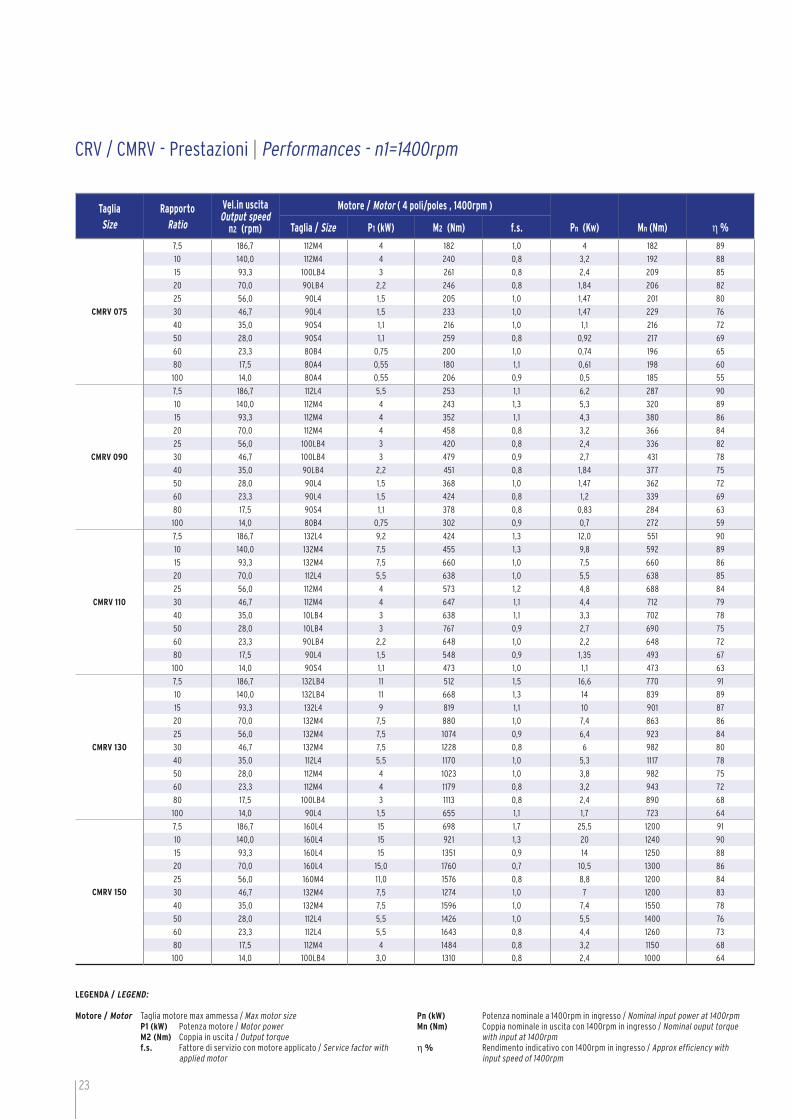
Taglia / Size P1 (kW) M2 (Nm) f.s. Pn (Kw) Mn (Nm) η %
CMRV 075
7,5 186,7 112M4 4 182 1,0 4 182 89
10 140,0 112M4 4 240 0,8 3,2 192 88
15 93,3 100LB4 3 261 0,8 2,4 209 85
20 70,0 90LB4 2,2 246 0,8 1,84 206 82
25 56,0 90L4 1,5 205 1,0 1,47 201 80
30 46,7 90L4 1,5 233 1,0 1,47 229 76
40 35,0 90S4 1,1 216 1,0 1,1 216 72
50 28,0 90S4 1,1 259 0,8 0,92 217 69
60 23,3 80B4 0,75 200 1,0 0,74 196 65
80 17,5 80A4 0,55 180 1,1 0,61 198 60
100 14,0 80A4 0,55 206 0,9 0,5 185 55
CMRV 090
7,5 186,7 112L4 5,5 253 1,1 6,2 287 90
10 140,0 112M4 4 243 1,3 5,3 320 89
15 93,3 112M4 4 352 1,1 4,3 380 86
20 70,0 112M4 4 458 0,8 3,2 366 84
25 56,0 100LB4 3 420 0,8 2,4 336 82
30 46,7 100LB4 3 479 0,9 2,7 431 78
40 35,0 90LB4 2,2 451 0,8 1,84 377 75
50 28,0 90L4 1,5 368 1,0 1,47 362 72
60 23,3 90L4 1,5 424 0,8 1,2 339 69
80 17,5 90S4 1,1 378 0,8 0,83 284 63
100 14,0 80B4 0,75 302 0,9 0,7 272 59
CMRV 110
7,5 186,7 132L4 9,2 424 1,3 12,0 551 90
10 140,0 132M4 7,5 455 1,3 9,8 592 89
15 93,3 132M4 7,5 660 1,0 7,5 660 86
20 70,0 112L4 5,5 638 1,0 5,5 638 85
25 56,0 112M4 4 573 1,2 4,8 688 84
30 46,7 112M4 4 647 1,1 4,4 712 79
40 35,0 10LB4 3 638 1,1 3,3 702 78
50 28,0 10LB4 3 767 0,9 2,7 690 75
60 23,3 90LB4 2,2 648 1,0 2,2 648 72
80 17,5 90L4 1,5 548 0,9 1,35 493 67
100 14,0 90S4 1,1 473 1,0 1,1 473 63
CMRV 130
7,5 186,7 132LB4 11 512 1,5 16,6 770 91
10 140,0 132LB4 11 668 1,3 14 839 89
15 93,3 132L4 9 819 1,1 10 901 87
20 70,0 132M4 7,5 880 1,0 7,4 863 86
25 56,0 132M4 7,5 1074 0,9 6,4 923 84
30 46,7 132M4 7,5 1228 0,8 6 982 80
40 35,0 112L4 5,5 1170 1,0 5,3 1117 78
50 28,0 112M4 4 1023 1,0 3,8 982 75
60 23,3 112M4 4 1179 0,8 3,2 943 72
80 17,5 100LB4 3 1113 0,8 2,4 890 68
100 14,0 90L4 1,5 655 1,1 1,7 723 64
CMRV 150
7,5 186,7 160L4 15 698 1,7 25,5 1200 91
10 140,0 160L4 15 921 1,3 20 1240 90
15 93,3 160L4 15 1351 0,9 14 1250 88
20 70,0 160L4 15,0 1760 0,7 10,5 1300 86
25 56,0 160M4 11,0 1576 0,8 8,8 1200 84
30 46,7 132M4 7,5 1274 1,0 7 1200 83
40 35,0 132M4 7,5 1596 1,0 7,4 1550 78
50 28,0 112L4 5,5 1426 1,0 5,5 1400 76
60 23,3 112L4 5,5 1643 0,8 4,4 1260 73
80 17,5 112M4 4 1484 0,8 3,2 1150 68
100 14,0 100LB4 3,0 1310 0,8 2,4 1000 64
CRV / CMRV - Prestazioni | Performances - n1=1400rpm
LEGENDA / LEGEND:
Motore / Motor Taglia motore max ammessa / Max motor size P1 (kW) Potenza motore / Motor power M2 (Nm) Coppia in uscita / Output torque f.s. Fattore di servizio con motore applicato / Service factor with applied motor
Pn (kW) Potenza nominale a 1400rpm in ingresso / Nominal input power at 1400rpmMn (Nm) Coppia nominale in uscita con 1400rpm in ingresso / Nominal ouput torque with input at 1400rpmη % Rendimento indicativo con 1400rpm in ingresso / Approx efficiency with input speed of 1400rpm


CRV-E
CMRV-E
CRV-E
CMRV-E
25
TagliaSize
G2 d(j6) A f b1 t1
030 45 9 20 / 3 10,2
040 53 11 23 / 4 12,5
050 64 14 30 M6 5 16
063 75 19 40 M6 6 21,5
075 90 24 50 M8 8 27
090 108 24 50 M8 8 27
110 135 28 60 M10 8 31
130 155 30 80 M10 8 33
150 175 35 80 M12 10 38
Serie CRV-E/CMRV-E | CRV-E/CMRV-E SeriesVite senza fi ne a doppia sporgenza | Double worm shaft

26
TagliaSize
PAM IEC N L P7,5 10 15 20 25 30 40 50 60 80 100
D025 56B14 50 65 80 9 9 9 9 / 9 9 9 9 / /
030
63B5 95 115 14011 11 11 11 11 11 11 11 11 11 /
63B14 60 75 90
56B5 80 100 1209 9 9 9 9 9 9 9 9 9 /
56B14 50 65 80
040
71B5 110 130 16014 14 14 14 14 14 14 14 14 14 /
71B14 70 85 105
63B5 95 115 14011 11 11 11 11 11 11 11 11 11 11
63B14 60 75 90
56B5 80 100 120 9 9 9 9 9 9 9 9 9 9 9
050
80B5 130 165 20019 19 19 19 19 19 / / 19 / /
80B14 80 100 120
71B5 110 130 16014 14 14 14 14 14 14 14 14 14 14
71B14 70 85 105
63B5 95 115 14011 11 11 11 11 11 11 11 11 11 11
63B14 60 75 90
063
90B5 130 165 20024 24 24 24 24 24 24 / / / /
90B14 95 115 140
80B5 130 165 20019 19 19 19 19 19 19 19 19 19 19
80B14 80 100 120
71B5 110 130 16014 14 14 14 14 14 14 14 14 14 14
71B14 70 85 105
075
100/112B5 180 215 25028 28 28 28 / / / / / / /
110/112B14 110 130 160
90B5 130 165 20024 24 24 24 24 24 24 24 24 24 24
90B14 95 115 140
80B5 130 165 20019 19 19 19 19 19 19 19 19 19 19
80B14 80 100 120
71B5 110 130 160 / / / / / / 14 14 14 14 14
090
100/112B5 180 215 25028 28 28 28 28 28 28 / / / /
100/112B14 110 130 160
90B5 130 165 20024 24 24 24 24 24 24 24 24 24 24
90B14 95 115 140
80B5 130 165 200/ / / / / / 19 19 19 19 19
80B14 80 100 120
110
132B5 230 265 300 38 38 38 38 / / / / / / /
100/112B5 180 215 25028 28 28 28 28 28 28 28 28 28 /
100/112B14 110 130 160
90B5 130 165 200 24 24 24 24 24 24 24 24 24 24 24
80B5 130 165 200 / / / / / / / / 19 19 19
130
132B5 230 265 300 38 38 38 38 38 38 38 / / / /
100/112B5 180 215 250/ / / / 28 28 28 28 28 28 28
100/112B14 110 130 160
90B5 130 165 200 / / / / / / / / / 24 24
150
160B5 250 300 350 42 42 42 42 / / / / / / /
132B5 230 265 300 / / / 38 38 38 38 38 / / /
100/112B5 180 215 250 / / / / / / / 28 28 28 28
Predisposizioni Attacco MotoreMotor Flange Adapters
27
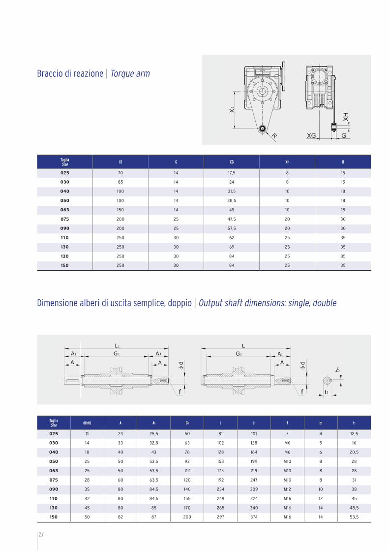
TagliaSize X1 G XG XH R
025 70 14 17,5 8 15
030 85 14 24 8 15
040 100 14 31,5 10 18
050 100 14 38,5 10 18
063 150 14 49 10 18
075 200 25 47,5 20 30
090 200 25 57,5 20 30
1 10 250 30 62 25 35
130 250 30 69 25 35
130 250 30 84 25 35
150 250 30 84 25 35
TagliaSize d(h6) A A1 G1 L L1 f b1 t1
025 11 23 25,5 50 81 101 / 4 12,5
030 14 33 32,5 63 102 128 M6 5 16
040 18 40 43 78 128 164 M6 6 20,5
050 25 50 53,5 92 153 199 M10 8 28
063 25 50 53,5 112 173 219 M10 8 28
075 28 60 63,5 120 192 247 M10 8 31
090 35 80 84,5 140 234 309 M12 10 38
1 10 42 80 84,5 155 249 324 M16 12 45
130 45 80 85 170 265 340 M16 14 48,5
150 50 82 87 200 297 374 M16 14 53,5
Braccio di reazione | Torque arm
Dimensione alberi di uscita semplice, doppio | Output shaft dimensions: single, double

28
TagliaSize
A B C D(H7) d(j6) E E1 F G G1 G2 H H1 l l1
025/030 54 / 97 14 / 80 70 32 45 63 / 40 35 30 25
025/040 70 / 121,5 18(19) / 100 70 43 45 78 / 50 35 40 25
030/040 70 20 121,5 18(19) 9 100 80 43 55 78 51 50 40 40 30
030/050 80 20 144 25(24) 9 120 80 49 55 92 51 60 40 50 30
030/063 100 20 174 25(28) 9 144 80 67 55 112 51 72 40 63 30
040/075 120 23 205 28(35) 11 172 100 72 70 120 60 86 50 75 40
040/090 140 23 238 35(38) 11 208 100 74 70 140 60 103 50 90 40
050/110 170 30 295 42 14 252,5 120 / 80 155 74 127,5 60 110 50
063/130 200 40 335 45 19 292,5 144 / 95 170 90 147,5 72 130 63
063/150 240 40 400 50 19 340 144 / 95 200 90 170 72 150 63
TagliaSize
L M N(h8) N1 N2 O P Q R R1 S T V Z X
025/030 65 56 55 29 22,5 6,5 75 44 57 48 5,5 21 27 100 44
025/040 75 71 60 36,5 22,5 6,5 87 55 71,5 48 6,5 26 35 115 60
030/040 75 71 60 36,5 29 6,5 87 55 71,5 57 6,5 26 35 120 60
030/050 85 85 70 43,5 29 8,5 100 64 84 57 7 30 40 130 70
030/063 95 103 80 53 29 8,5 1 10 80 102 57 8 36 50 145 85
040/075 115 112 95 57 36,5 11 140 93 119 71,5 10 40 60 165 90
040/090 130 130 110 67 36,5 13 160 102 135 71,5 11 45 70 182 100
050/110 165 144 130 74 43,5 14 200 125 167,5 84 14 50 85 225 115
063/130 215 155 180 81 53 16 250 140 187,5 102 15 60 100 245 120
063/150 215 185 180 96 53 18 250 180 230 102 18 72,5 120 275 145
Serie Riduttori Combinati CRR-CMRR | CRR-CMRR Combined Reducer SeriesDimensione e ingombri riduttori CRR-CMRR | CRR-CMRR reducers overall dimensions
CRR CMRRF
CMRR
ØXQØXL
ØXO
ØXN
α1
ØXP
XA
XB
XC
C
HR Q
V
I
S
ØL
A
E
H Z
G1
T T
ØD
t
b
G
N N
M
X
F
1
1 1
ØN
P
XE
E
G
G B
N
Ød
t1
b1
1
2
2
RQ
I
11
1αØO

29
B8/D B8/S V5/D V5/S
V6/D V6/S B3/D B3/S
— Se non specificato viene fornita posizione B3/S. - Unless otherwise specified, the product are supplied with B3/S position.— Per posizione morsettiera vedere tabella a pag. 6. - For motor position refer to page 6 table.
Dimensione e ingombri riduttori CRR-CMRR | CRR-CMRR reducers overall dimensions
CRR-CMRR | CRR-CMRRPosizioni di montaggio | Mounting positions
TagliaSize
XA XB XCXE α b t b1 t1 f kg
F FB FL FE FD F FB FL FE FD F FB FL FE FD
025/030 54,5 / / / / 6 / / / / 4 / / / / M6x11 (n.4) 0° 5 16,3 / / / 2,1
025/040 67 76,5 97 / / 7 9 7 / / 4 5 4 / / M6x8 (n.4) 45° 6(6) 20,8(21,8) / / / 3,2
030/040 67 76,5 97 / / 7 9 7 / / 4 5 4 / / M6x8 (n.4) 45° 6(6) 20,8(21,8) 3 10,2 / 3,9
030/050 90 87,5 120 / / 9 10 9 / / 5 5 5 / / M8x10 (n.4) 45° 8(8) 28,3(27,3) 3 10,2 / 5
030/063 82 99 112 80,5 / 10 11 10 13,5 / 6 5 6 6 / M8x14 (n.8) 45° 8(8) 28,3(31,3) 3 10,2 / 7,8
040/075 111 / 90 / / 13 / 13 / / 6 / 6 / / M8x14 (n.8) 45° 8(10) 31,3(38,3) 4 12,5 / 12
040/090 111 110 122 / 151 13 17 18 / 13 6 6 6 / 6 M10x18 (n.8) 45° 10(10) 38,3(41,3) 4 12,5 / 16
050/110 131 / / / / 15 / / / / 6 / / / / M10x18 (n.8) 45° 12 45,3 5 16 M6 39,2
063/130 140 / / / / 15 / / / / 6 / / / / M12x21 (n.8) 45° 14 48,8 6 21,5 M6 55
063/150 155 / / / / 15 / / / / 6 / / / / M12x21 (n.8) 45° 14 54 6 21,5 M6 93
TagliaSize
Ø XP Ø XL Ø XOα
Ø XN (H8) XQ
F FB FL FE FD F FB FL FE FD F FB FL FE FD F FB FL FE FD F FB FL FE FD
025/030 80 / / / / 68 / / / / 6,5(n.4) / / / / 45° 50 / / / / 70 / / / /
025/040 110 140 110 / / 80/87 115 80/87 / / 9(n.4) 9,5(n.4) 9(n.4) / / 45° 60 95 60 / / 95 / 95 / /
030/040 110 140 110 / / 80/87 115 80/87 / / 9(n.4) 9,5(n.4) 9(n.4) / / 45° 60 95 60 / / 95 / 95 / /
030/050 125 160 125 / / 90 130 90 / / 11(n.4) 9,5(n.4) 11(n.4) / / 45° 70 110 70 / / 110 / 110 / /
030/063 180 200 180 160 / 150 165 150 130 / 11(n.4) 11(n.4) 11(n.4) 11(n.4) / 45° 115 130 115 110 / 142 / 142 / /
040/075 200 / 160 / / 165 / 130 / / 14(n.4) / 14(n.4) / / 45° 130 / 110 / / 170 / 160 / /
040/090 210 200 250 / 210 175 165 215 / 175 14(n.4) 11(n.4) 14(n.4) / 14(n.4) 45° 152 130 180 / 152 200 / 230 / /
050/110 280 / / / / 230 / / / / 14(n.8) / / / / 45° 170 / / / / 260 / / / /
063/130 320 / / / / 255 / / / / 16(n.8) / / / / 22,5° 180 / / / / 290 / / / /
063/150 320 / / / / 255 / / / / 16(n.8) / / / / 22,5° 180 / / / / 290 / / / /

30
TagliaSize
RapportoRatio
Vel.in uscita Output speed
n2 (rpm)
Motore / Motor ( 4 poli/poles , 1400rpm )
Taglia / Size P1 (kW) M2 (Nm) f.s. η %
CMRR 025/030
100 14 56B4 0,09 38 0,8 62 150 9,3 56A4 0,06 33 0,9 53 200 7 56A4 0,06 41 0,8 50 250 5,6 56A4 0,06 44 0,8 43 300 4,7 56A4 0,06 50 0,6 41 400 3,5 56A4 0,06 71 0,5 44 500 2,8 56A4 0,06 77 0,5 37 600 2,3 56A4 0,06 90 0,3 36 750 1,9 56A4 0,06 101 0,3 33 900 1,6 56A4 0,06 119 0,3 33 1200 1,2 56A4 0,06 141 0,2 30 1500 0,9 56A4 0,06 165 0,2 26 1800 0,78 56A4 0,06 203 0,2 28 2400 0,58 56A4 0,06 227 0,2 23 3000 0,47 56A4 0,06 270 0,2 22
CMRR 025/040
300 4,7 56B4 0,09 88 0,8 48 400 3,5 56A4 0,06 71 0,9 43 500 2,8 56A4 0,06 82 0,7 40 600 2,3 56A4 0,06 101 0,6 41 750 1,9 56A4 0,06 116 0,5 38 900 1,6 56A4 0,06 143 0,5 40 1200 1,2 56A4 0,06 171 0,4 36 1500 0,93 56A4 0,06 197 0,3 31 1800 0,78 56A4 0,06 217 0,3 30 2400 0,58 56A4 0,06 268 0,2 27 3000 0,47 56A4 0,06 324 0,2 27 4000 0,35 56A4 0,06 294 0,1 18 5000 0,28 56A4 0,06 356 0,1 17
CMRR 030/040
300 4,7 56B4 0,09 88 0,8 48 400 3,5 56A4 0,06 70 0,9 43 500 2,8 56A4 0,06 96 0,6 47 600 2,3 56A4 0,06 104 0,7 42 750 1,9 56A4 0,06 121 0,6 40 900 1,6 56A4 0,06 139 0,5 39 1200 1,2 56A4 0,06 166 0,4 35 1500 0,93 56A4 0,06 196 0,4 32 1800 0,78 56A4 0,06 218 0,3 30 2400 0,58 56A4 0,06 261 0,2 26 3200 0,44 56A4 0,06 300 0,2 23 4000 0,35 56A4 0,06 279 0,1 17 5000 0,28 56A4 0,06 338 0,1 17
CMRR 030/050
300 4,7 63A4 0,12 119 1,2 49 400 3,5 63A4 0,12 142 0,9 43 500 2,8 63A4 0,12 164 0,7 40 600 2,3 56B4 0,09 159 0,9 43 750 1,9 56B4 0,09 185 0,8 41 900 1,6 56B4 0,09 212 0,7 39 1200 1,2 56A4 0,06 169 0,7 35 1500 0,93 56A4 0,06 199 0,7 32 1800 0,78 56A4 0,06 222 0,7 30 2400 0,58 56A4 0,06 266 0,5 27 3000 0,47 56A4 0,06 307 0,4 25 4000 0,35 56A4 0,06 288 0,3 18 4800 0,29 56A4 0,06 311 0,3 16
CMRR 030/063
300 4,7 63C4 0,25 238 1,0 47 400 3,5 63C4 0,25 307 0,7 45 500 2,8 63B4 0,18 257 0,8 42 600 2,3 63A4 0,12 208 1,1 42 750 1,9 63A4 0,12 241 0,9 40 900 1,6 56B4 0,09 200 1,0 37 1200 1,2 56B4 0,09 263 0,9 37 1500 0,93 56B4 0,09 305 0,7 33 1800 0,78 56A4 0,06 225 0,9 31 2400 0,58 56A4 0,06 276 0,8 28 3000 0,47 56A4 0,06 319 0,7 24 4000 0,35 56A4 0,06 306 0,6 19 5000 0,28 56A4 0,06 360 0,4 18
LEGENDA / LEGEND:Motore / Motor Taglia motore max ammessa / Max motor size f.s. Fattore di servizio con motore applicato / Service factor with applied motoP1 (kW) Potenza motore / Motor power η % Rendimento indicativo con 1400rpm in ingresso / Approx effi ciency with input speed of 1400rpmM2 (Nm) Coppia in uscita / Output torque
Serie Riduttori Combinati CRR-CMRR | CRR-CMRR Combined Reducer SeriesCMRR - Prestazioni | Performances - n1=1400rpm

31
CMRR - Prestazioni | Performances - n1=1400rpm
TagliaSize
RapportoRatio
Vel.in uscita Output speed
n2 (rpm)
Motore / Motor ( 4 poli/poles , 1400rpm )
Taglia / Size P1 (kW) M2 (Nm) f.s. η %
CMRR 040/075
300 4,7 63C4 0,37 405 1,0 54400 3,5 63B4 0,25 337 1,0 49500 2,8 63B4 0,25 384 0,8 45600 2,3 63B4 0,18 362 1,1 48750 1,9 63B4 0,18 435 0,9 48900 1,6 63B4 0,18 487 1,0 451200 1,2 63A4 0,12 399 0,9 421500 0,93 56B4 0,09 360 0,7 391800 0,78 56B4 0,09 404 0,9 372400 0,58 56B4 0,09 496 0,8 333200 0,44 56A4 0,06 377 0,7 294000 0,35 56A4 0,06 355 0,6 225000 0,28 56A4 0,06 419 0,4 20
CMRR 040/090
300 4,7 63C4 0,37 402 1,5 53400 3,5 63C4 0,37 523 1,2 52500 2,8 63C4 0,37 611 0,9 48600 2,3 63C4 0,37 757 0,8 49750 1,9 63B4 0,25 598 0,9 48900 1,6 63B4 0,25 667 0,8 451200 1,2 63B4 0,18 629 1,0 441500 0,93 63B4 0,18 735 0,8 401800 0,78 63A4 0,12 547 0,9 372400 0,58 63A4 0,12 695 0,9 353200 0,44 56B4 0,09 609 0,9 314000 0,35 56B4 0,09 548 0,8 225000 0,28 56A4 0,06 431 1,0 21
CMRR 050/110
300 4,7 80C4 1,10 1278 1,0 57400 3,5 80B4 0,75 1127 1,1 55500 2,8 80A4 0,55 984 1,1 52600 2,3 80A4 0,55 1181 1,0 52750 1,9 80A4 0,55 1411 0,9 51900 1,6 71B4 0,37 1079 1,2 491200 1,2 71B4 0,37 1396 0,8 471500 0,93 71A4 0,25 1064 1,2 411800 0,78 71A4 0,25 1195 1,1 392400 0,58 63B4 0,18 1113 1,1 383000 0,47 63A4 0,12 884 1,2 344000 0,35 63A4 0,12 784 1,0 245000 0,28 63A4 0,12 928 0,8 23
CMRR 063/130
300 4,7 90L4 1,50 1789 1,0 59400 3,5 90S4 1,10 1671 1,0 56500 2,8 90S4 1,10 1991 0,8 53600 2,3 80B4 0,75 1631 1,0 52750 1,9 80B4 0,75 2005 0,9 53900 1,6 80B4 0,75 2283 0,8 511200 1,2 80A4 0,55 2132 0,8 491500 0,93 71B4 0,37 1674 1,1 441800 0,78 71B4 0,37 1887 0,9 422400 0,58 71A4 0,25 1624 1,0 393000 0,47 71A4 0,25 1935 0,8 364000 0,35 71A4 0,25 2046 0,6 305000 0,28 71A4 0,25 2430 0,5 28
CMRR 063/150
300 4,7 90L4 1,50 1860 1,2 61
400 3,5 90L4 1,50 2208 1,2 54
500 2,80 90L4 1,50 2582 0,9 50
750 1,9 90S4 1,10 2616 0,9 47
900 1,6 80B4 0,75 2123 1,0 47
1800 0,80 80A4 0,55 2638 0,8 40
3000 0,5 71B4 0,37 2535 0,9 36
LEGENDA / LEGEND:Motore / Motor Taglia motore max ammessa / Max motor size f.s. Fattore di servizio con motore applicato / Service factor with applied motoP1 (kW) Potenza motore / Motor power η % Rendimento indicativo con 1400rpm in ingresso / Approx efficiency with input speed of 1400rpmM2 (Nm) Coppia in uscita / Output torque
32
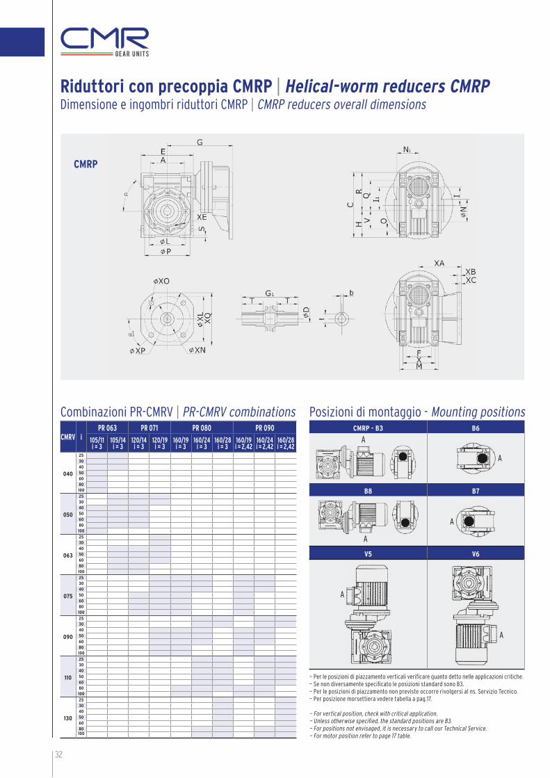
CMRV iPR 063 PR 071 PR 080 PR 090
105/11i = 3
105/14i = 3
120/14i = 3
120/19i = 3
160/19i = 3
160/24i = 3
160/28i = 3
160/19i = 2,42
160/24i = 2,42
160/28i = 2,42
040
253040506080100
050
253040506080100
063
253040506080100
075
253040506080100
090
253040506080100
110
253040506080100
130
253040506080100
CMRP
Riduttori con precoppia CMRP | Helical-worm reducers CMRPDimensione e ingombri riduttori CMRP | CMRP reducers overall dimensions
Combinazioni PR-CMRV | PR-CMRV combinations
— Per le posizioni di piazzamento verticali verifi care quanto detto nelle applicazioni critiche.— Se non diversamente specifi cato le posizioni standard sono B3.— Per le posizioni di piazzamento non previste occorre rivolgersi al ns. Servizio Tecnico.— Per posizione morsettiera vedere tabella a pag.17.
— For vertical position, check with critical application.— Unless otherwise specifi ed, the standard positions are B3.— For positions not envisaged, it is necessary to call our Technical Service.— For motor position refer to page 17 table.
Posizioni di montaggio - Mounting positionsCMRP - B3 B6
B8 B7
V5 V6
A
A
A
A
A
A
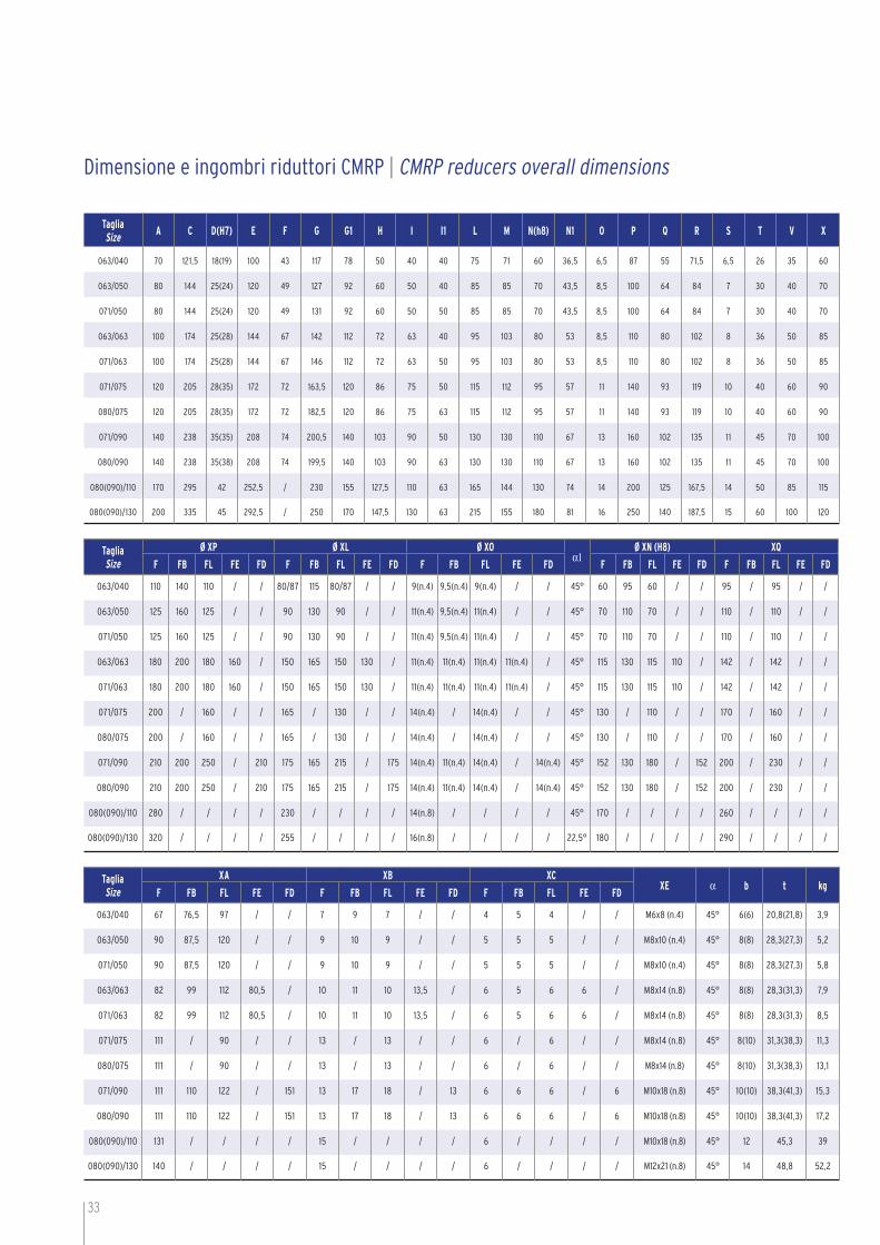
33
TagliaSize
A C D(H7) E F G G1 H I I1 L M N(h8) N1 O P Q R S T V X
063/040 70 121,5 18(19) 100 43 117 78 50 40 40 75 71 60 36,5 6,5 87 55 71,5 6,5 26 35 60
063/050 80 144 25(24) 120 49 127 92 60 50 40 85 85 70 43,5 8,5 100 64 84 7 30 40 70
071/050 80 144 25(24) 120 49 131 92 60 50 50 85 85 70 43,5 8,5 100 64 84 7 30 40 70
063/063 100 174 25(28) 144 67 142 112 72 63 40 95 103 80 53 8,5 110 80 102 8 36 50 85
071/063 100 174 25(28) 144 67 146 112 72 63 50 95 103 80 53 8,5 110 80 102 8 36 50 85
071/075 120 205 28(35) 172 72 163,5 120 86 75 50 115 112 95 57 11 140 93 119 10 40 60 90
080/075 120 205 28(35) 172 72 182,5 120 86 75 63 115 112 95 57 11 140 93 119 10 40 60 90
071/090 140 238 35(35) 208 74 200,5 140 103 90 50 130 130 110 67 13 160 102 135 11 45 70 100
080/090 140 238 35(38) 208 74 199,5 140 103 90 63 130 130 110 67 13 160 102 135 11 45 70 100
080(090)/110 170 295 42 252,5 / 230 155 127,5 110 63 165 144 130 74 14 200 125 167,5 14 50 85 115
080(090)/130 200 335 45 292,5 / 250 170 147,5 130 63 215 155 180 81 16 250 140 187,5 15 60 100 120
TagliaSize
Ø XP Ø XL Ø XOα1
Ø XN (H8) XQ
F FB FL FE FD F FB FL FE FD F FB FL FE FD F FB FL FE FD F FB FL FE FD
063/040 110 140 110 / / 80/87 115 80/87 / / 9(n.4) 9,5(n.4) 9(n.4) / / 45° 60 95 60 / / 95 / 95 / /
063/050 125 160 125 / / 90 130 90 / / 11(n.4) 9,5(n.4) 11(n.4) / / 45° 70 110 70 / / 110 / 110 / /
071/050 125 160 125 / / 90 130 90 / / 11(n.4) 9,5(n.4) 11(n.4) / / 45° 70 110 70 / / 110 / 110 / /
063/063 180 200 180 160 / 150 165 150 130 / 11(n.4) 11(n.4) 11(n.4) 11(n.4) / 45° 115 130 115 110 / 142 / 142 / /
071/063 180 200 180 160 / 150 165 150 130 / 11(n.4) 11(n.4) 11(n.4) 11(n.4) / 45° 115 130 115 110 / 142 / 142 / /
071/075 200 / 160 / / 165 / 130 / / 14(n.4) / 14(n.4) / / 45° 130 / 110 / / 170 / 160 / /
080/075 200 / 160 / / 165 / 130 / / 14(n.4) / 14(n.4) / / 45° 130 / 110 / / 170 / 160 / /
071/090 210 200 250 / 210 175 165 215 / 175 14(n.4) 11(n.4) 14(n.4) / 14(n.4) 45° 152 130 180 / 152 200 / 230 / /
080/090 210 200 250 / 210 175 165 215 / 175 14(n.4) 11(n.4) 14(n.4) / 14(n.4) 45° 152 130 180 / 152 200 / 230 / /
080(090)/110 280 / / / / 230 / / / / 14(n.8) / / / / 45° 170 / / / / 260 / / / /
080(090)/130 320 / / / / 255 / / / / 16(n.8) / / / / 22,5° 180 / / / / 290 / / / /
TagliaSize
XA XB XCXE α b t kg
F FB FL FE FD F FB FL FE FD F FB FL FE FD
063/040 67 76,5 97 / / 7 9 7 / / 4 5 4 / / M6x8 (n.4) 45° 6(6) 20,8(21,8) 3,9
063/050 90 87,5 120 / / 9 10 9 / / 5 5 5 / / M8x10 (n.4) 45° 8(8) 28,3(27,3) 5,2
071/050 90 87,5 120 / / 9 10 9 / / 5 5 5 / / M8x10 (n.4) 45° 8(8) 28,3(27,3) 5,8
063/063 82 99 112 80,5 / 10 11 10 13,5 / 6 5 6 6 / M8x14 (n.8) 45° 8(8) 28,3(31,3) 7,9
071/063 82 99 112 80,5 / 10 11 10 13,5 / 6 5 6 6 / M8x14 (n.8) 45° 8(8) 28,3(31,3) 8,5
071/075 111 / 90 / / 13 / 13 / / 6 / 6 / / M8x14 (n.8) 45° 8(10) 31,3(38,3) 11,3
080/075 111 / 90 / / 13 / 13 / / 6 / 6 / / M8x14 (n.8) 45° 8(10) 31,3(38,3) 13,1
071/090 111 110 122 / 151 13 17 18 / 13 6 6 6 / 6 M10x18 (n.8) 45° 10(10) 38,3(41,3) 15,3
080/090 111 110 122 / 151 13 17 18 / 13 6 6 6 / 6 M10x18 (n.8) 45° 10(10) 38,3(41,3) 17,2
080(090)/110 131 / / / / 15 / / / / 6 / / / / M10x18 (n.8) 45° 12 45,3 39
080(090)/130 140 / / / / 15 / / / / 6 / / / / M12x21 (n.8) 45° 14 48,8 52,2
Dimensione e ingombri riduttori CMRP | CMRP reducers overall dimensions
Posizioni di montaggio - Mounting positions

34
TagliaSize
Ingresso / Input side Uscita / Output sideR L D1 F1 C1 d1 IEC D2 F2 C2 d2 IEC
063
1/340 47 140 115 95 11 63B5 105 85 70
11 -
14 71B14
071
1/350 51 160 130 110 14 71B5 120 100 80
14 -
19 80B14
080
1/363 70 200 165 130 19 80B5 160 130 110
19 -
24 -
28 100B14
090
1/2,4375 75 200 165 130 24 90B5 160 130 110
19 -
24 -
28 100B14
Riduttori con precoppia PR | Helical-worm reducers PRDimensione e ingombri riduttori PR | PR helical stage overall dimensions
35
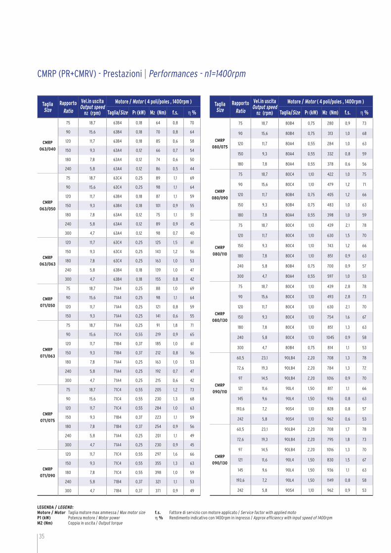
CMRP (PR+CMRV) - Prestazioni | Performances - n1=1400rpm
TagliaSize
RapportoRatio
Vel.in uscita Output speed
n2 (rpm)
Motore / Motor ( 4 poli/poles , 1400rpm )
Taglia/Size P1 (kW) M2 (Nm) f.s. η %
CMRP
063/040
75 18,7 63B4 0,18 64 0,8 70
90 15,6 63B4 0,18 70 0,8 64
120 11,7 63B4 0,18 85 0,6 58
150 9,3 63A4 0,12 66 0,7 54
180 7,8 63A4 0,12 74 0,6 50
240 5,8 63A4 0,12 86 0,5 44
CMRP
063/050
75 18,7 63C4 0,25 89 1,1 69
90 15,6 63C4 0,25 98 1,1 64
120 11,7 63B4 0,18 87 1,1 59
150 9,3 63B4 0,18 101 0,9 55
180 7,8 63A4 0,12 75 1,1 51
240 5,8 63A4 0,12 89 0,9 45
300 4,7 63A4 0,12 98 0,7 40
CMRP
063/063
120 11,7 63C4 0,25 125 1,5 61
150 9,3 63C4 0,25 143 1,2 56
180 7,8 63C4 0,25 163 1,0 53
240 5,8 63B4 0,18 139 1,0 47
300 4,7 63B4 0,18 155 0,8 42
CMRP
071/050
75 18,7 71A4 0,25 88 1,0 69
90 15,6 71A4 0,25 98 1,1 64
120 11,7 71A4 0,25 121 0,8 59
150 9,3 71A4 0,25 141 0,6 55
CMRP
071/063
75 18,7 71A4 0,25 91 1,8 71
90 15,6 71C4 0,55 219 0,9 65
120 11,7 71B4 0,37 185 1,0 61
150 9,3 71B4 0,37 212 0,8 56
180 7,8 71A4 0,25 163 1,0 53
240 5,8 71A4 0,25 192 0,7 47
300 4,7 71A4 0,25 215 0,6 42
CMRP
071/075
75 18,7 71C4 0,55 205 1,2 73
90 15,6 71C4 0,55 230 1,3 68
120 11,7 71C4 0,55 284 1,0 63
150 9,3 71B4 0,37 223 1,1 59
180 7,8 71B4 0,37 254 0,9 56
240 5,8 71A4 0,25 201 1,1 49
300 4,7 71A4 0,25 230 0,9 45
CMRP
071/090
120 11,7 71C4 0,55 297 1,6 66
150 9,3 71C4 0,55 355 1,3 63
180 7,8 71C4 0,55 398 1,0 59
240 5,8 71B4 0,37 321 1,1 53
300 4,7 71B4 0,37 371 0,9 49
TagliaSize
RapportoRatio
Vel.in uscita Output speed
n2 (rpm)
Motore / Motor ( 4 poli/poles , 1400rpm )
Taglia/Size P1 (kW) M2 (Nm) f.s. η %
CMRP
080/075
75 18,7 80B4 0,75 280 0,9 73
90 15,6 80B4 0,75 313 1,0 68
120 11,7 80A4 0,55 284 1,0 63
150 9,3 80A4 0,55 332 0,8 59
180 7,8 80A4 0,55 378 0,6 56
CMRP
080/090
75 18,7 80C4 1,10 422 1,0 75
90 15,6 80C4 1,10 479 1,2 71
120 11,7 80B4 0,75 405 1,2 66
150 9,3 80B4 0,75 483 1,0 63
180 7,8 80A4 0,55 398 1,0 59
CMRP
080/110
75 18,7 80C4 1,10 439 2,1 78
120 11,7 80C4 1,10 630 1,5 70
150 9,3 80C4 1,10 743 1,2 66
180 7,8 80C4 1,10 851 0,9 63
240 5,8 80B4 0,75 700 0,9 57
300 4,7 80A4 0,55 597 1,0 53
CMRP
080/130
75 18,7 80C4 1,10 439 2,8 78
90 15,6 80C4 1,10 493 2,8 73
120 11,7 80C4 1,10 630 2,1 70
150 9,3 80C4 1,10 754 1,6 67
180 7,8 80C4 1,10 851 1,3 63
240 5,8 80C4 1,10 1045 0,9 58
300 4,7 80B4 0,75 814 1,1 53
CMRP
090/110
60,5 23,1 90LB4 2,20 708 1,3 78
72,6 19,3 90LB4 2,20 784 1,3 72
97 14,5 90LB4 2,20 1016 0,9 70
121 11,6 90L4 1,50 817 1,1 66
145 9,6 90L4 1,50 936 0,8 63
193,6 7,2 90S4 1,10 828 0,8 57
242 5,8 90S4 1,10 962 0,6 53
CMRP
090/130
60,5 23,1 90LB4 2,20 708 1,7 78
72,6 19,3 90LB4 2,20 795 1,8 73
97 14,5 90LB4 2,20 1016 1,3 70
121 11,6 90L4 1,50 830 1,5 67
145 9,6 90L4 1,50 936 1,1 63
193,6 7,2 90L4 1,50 1149 0,8 58
242 5,8 90S4 1,10 962 0,9 53
LEGENDA / LEGEND:Motore / Motor Taglia motore max ammessa / Max motor size f.s. Fattore di servizio con motore applicato / Service factor with applied motoP1 (kW) Potenza motore / Motor power η % Rendimento indicativo con 1400rpm in ingresso / Approx efficiency with input speed of 1400rpmM2 (Nm) Coppia in uscita / Output torque
36
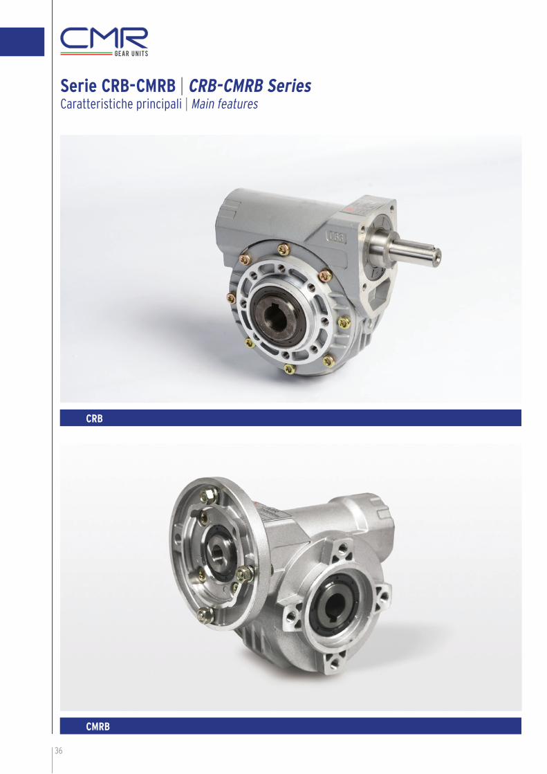
Serie CRB-CMRB | CRB-CMRB SeriesCaratteristiche principali | Main features
CMRB
CRB
CMRB

37
N. Componenti Parts
10 Paraolio Oil seal
11 Guarnizione Gasket
12 Tappo olio Oil plug
13 Linguetta Key
14 Vite testa brugola Intl.hex screw
15 Seeger Snap ring
16 Guarnizione Gasket
17 Vite testa brugola Intl.hex screw
N. Componenti Parts
1 Corpo Housing
2 Corona Worm wheel
3 Vite senza fi ne Worm screw
4 Flangia Flange
5 Flangia Flange
6 Coperchio Seal cover
7 Cuscinetto Bearing
8 Cuscinetto Bearing
9 Paraolio Oil seal
TagliaSize
Rapporti disponibiliAvailable ratios
30 7 10 15 19 30 39 61 80
45 7 10 14 21 28 37 46 60 70 102
50 7 10 14 18 26 36 43 60 68 80 100
63 7 10 15 19 24 30 36 45 67 80 94
Caratteristiche principali | Main features

38
Gamma di riduttori CMRB e CRB
CARATTERISTICHE DEI PRODOTTI:
1 - Carcassa realizzata in lega di alluminio impregnato dopo lavorazione.
2 - Componenti interni realizzati con materiali selezionati e lavorazioni controllate.
3 - Elevata coppia trasmissibile.
4 - Notevole affi dabilità e funzionamento estremamente silenzioso.
CMRB and CRB range
FEATURES OF THE PRODUCTS:
1 - Alluminium alloy impregnated after machining.
2 - Internal parts made with selected materials and highly controlled machinings.
3 - High transmissible torque.
4 - High reliability and extremely noiseless operation.
Sigla di identifi cazione del prodotto: Product type identifi cation:
CodiceCode
DescrizioneDescription
CMRB Sigla prodotto CMRB con fl angia di ingresso, CRB senza fl angia di ingressoProduct identifi cation CMRB: with input fl ange, CRB: without input fl ange
63 GrandezzaSize
40 Rapporto di riduzioneReduction ratio
E E: per vite a doppia sporgenza, senza sigla per vite standardE: for double extension worm shaft, “no mark”: for standard worm screw
F1 Tipo di fl angia di uscita, senza sigla fl angia assenteOutput fl ange type: “no mark”: no fl ange
P PiedeSupport
71B5 Tipo di motore applicabileSuitable type of motor
39
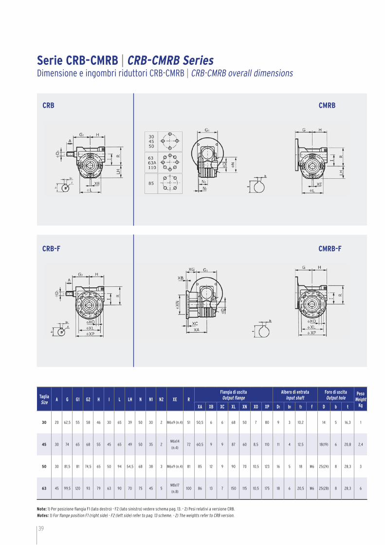
TagliaSize
A G G1 G2 H I L LH N N1 N2 XE R
Flangia di uscitaOutput fl ange
Albero di entrataInput shaft
Foro di uscitaOutput hole
PesoWeight
KgXA XB XC XL XN XO XP D1 b1 t1 f D b t
30 20 62,5 55 58 46 30 65 39 50 30 2 M6x9 (n.4) 51 50,5 6 6 68 50 7 80 9 3 10,2 14 5 16,3 1
45 30 74 65 68 55 45 65 49 50 35 2M6x14
(n.4)72 60,5 9 9 87 60 8,5 110 11 4 12,5 18(19) 6 20,8 2,4
50 30 81,5 81 74,5 65 50 94 54,5 68 38 3 M6x9 (n.4) 81 85 12 9 90 70 10,5 123 16 5 18 M6 25(24) 8 28,3 3
63 45 99,5 120 93 79 63 90 70 75 45 5M8x17
(n.8)100 86 13 7 150 115 10,5 175 18 6 20,5 M6 25(28) 8 28,3 6
Note: 1) Per posizione fl angia F1 (lato destro) - F2 (lato sinistro) vedere schema pag. 13. - 2) Pesi relativi a versione CRB.
Notes: 1) For fl ange position F1 (right side) - F2 (left side) refer to pag. 13 scheme. - 2) The weights refer to CRB version.
Serie CRB-CMRB | CRB-CMRB SeriesDimensione e ingombri riduttori CRB-CMRB | CRB-CMRB overall dimensions
CRB
CRB-F
CMRB
CMRB-F

40
Serie CRB-CMRB con piedi | CRB-CMRB with feet SeriesDimensione e ingombri riduttori CRB-CMRB | CRB-CMRB overall dimensions
TagliaSize
A B C C1 C2 E G G1 G2 H I K LL M O W
Albero di entrataInput shaft
Foro di uscitaOutput hole
PesoWeight
KgD1 b1 t1 f D b t
30 20 50 106 94 78 62,5 55 58 46 30 65~66 55 87 6,5 3 9 3 10,2 14 5 16,3 1,1
45 30 50~52 144 1 121 98 74 65 68 55 45 80~81 72 100 10,5 3 11 4 12,5 18 6 20,8 2,6
50 30 63~65 163 138,5 113 81,5 81 74,5 65 50 98~100 82 123 10,5 3,5 16 5 18 M6 25 8 28,3 3,4
63 45 95 200 170 133 99,5 120 93 79 63 110~111 100 144 10,5 4 18 6 20,5 M6 25 8 28,3 6,6
CRB-S CMRB-S
CRB-A CMRB-A
CRB-V CMRB-V
41
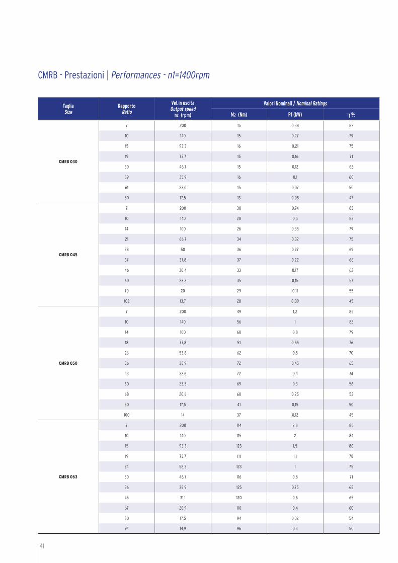
CMRB - Prestazioni | Performances - n1=1400rpm
TagliaSize
RapportoRatio
Vel.in uscita Output speed
n2 (rpm)
Valori Nominali / Nominal Ratings
M2 (Nm) P1 (kW) η %
CMRB 030
7 200 15 0,38 83
10 140 15 0,27 79
15 93,3 16 0,21 75
19 73,7 15 0,16 71
30 46,7 15 0,12 62
39 35,9 16 0,1 60
61 23,0 15 0,07 50
80 17,5 13 0,05 47
CMRB 045
7 200 30 0,74 85
10 140 28 0,5 82
14 100 26 0,35 79
21 66,7 34 0,32 75
28 50 36 0,27 69
37 37,8 37 0,22 66
46 30,4 33 0,17 62
60 23,3 35 0,15 57
70 20 29 0,11 55
102 13,7 28 0,09 45
CMRB 050
7 200 49 1,2 85
10 140 56 1 82
14 100 60 0,8 79
18 77,8 51 0,55 76
26 53,8 62 0,5 70
36 38,9 72 0,45 65
43 32,6 72 0,4 61
60 23,3 69 0,3 56
68 20,6 60 0,25 52
80 17,5 41 0,15 50
100 14 37 0,12 45
CMRB 063
7 200 114 2,8 85
10 140 115 2 84
15 93,3 123 1,5 80
19 73,7 111 1,1 78
24 58,3 123 1 75
30 46,7 116 0,8 71
36 38,9 125 0,75 68
45 31,1 120 0,6 65
67 20,9 110 0,4 60
80 17,5 94 0,32 54
94 14,9 96 0,3 50

42
Dimensione accessori | Accessories dimensions
Braccio di reazione | Torque arm
SchemaChart
TagliaSize
A d d0 D1 D2 D3 G R SCRB
30 100 80 7 50 8 65 4 18 4
45 100 90 7 50 8 65 4 13 4
50 100 110 7 68 8 94 4 18 4
63 150 110 9 75 10 90 20 30 6
Dimensioni alberi di uscita semplice, doppio | Output shaft dimensions: single, double
SchemaChart
TagliaSize
d(h6) A A1 G1 L L1 b1 t1
CRB
30 14 25 35,5 55 95 126 5 16,3
4518 32 43
50113 151
420,8
(19) (40) (58,5) (128,5) (182) (21,8)
5025 52 60
81146 200
828,3
(24) (50) (68,5) (155) (218) (27,3)
63 25 60 63 120 190 246,4 8 28,3
Vite senza fi ne a doppia sporgenza | Double worm shaft end (-E)
SchemaChart
TagliaSize
d(h6) A G2
CRB
30 9 20 47
45 11 30 56
50 16 30 67
63 18 45 81

43
TagliaSize
PAMIEC
N L P7 10 15 19 30 39 61 80
D
030
63B5 95 115 14011 11 11 11 11 11 / /
63B14 * 60 75 90
56B5 80 100 1209 9 9 9 9 9 9 9
56B14 * 50 65 80
TagliaSize
PAMIEC
N L P7 10 14 21 28 37 46 60 70 102
D
045
71B5 110 130 16014 14 14 14 14 14 14 / 14 /
71B14* 70 85 105
63B5 95 115 14011 11 11 11 11 11 11 11 11 11
63B14* 60 75 90
56B5 80 100 120 / / / / / 9 9 9 9 9
TagliaSize
PAMIEC
N L P7 10 14 18 26 36 43 60 68 80 100
D
050
80B5 130 165 20019 19 19 19 19 / / / / / /
80B14* 80 100 120
71B5 110 130 16014 14 14 14 14 14 14 14 / 14 /
71B14* 70 85 105
63B5 95 115 140 / / / / 11 11 11 11 11 11 11
TagliaSize
PAMIEC
N L P7 10 15 19 24 30 36 45 67 80 94
D
063
90B5 130 165 20024 24 24 24 24 24 / / / / /
90B14 95 115 140
80B5 130 165 20019 19 19 19 19 19 19 19 19 19 19
80B14* 80 100 120
71B5 110 130 160/ / / / / 14 14 14 14 14 14
71B14* 70 85 105
*: Accoppiamento fl angia-motore sfasato di 45°. - *: Once coupled the motor is rotated by 45°.
Predisposizione attacco motore | Motor adapters
Dimensioni alberi di uscita semplice, doppio | Output shaft dimensions: single, double
Vite senza fi ne a doppia sporgenza | Double worm shaft end (-E)
44
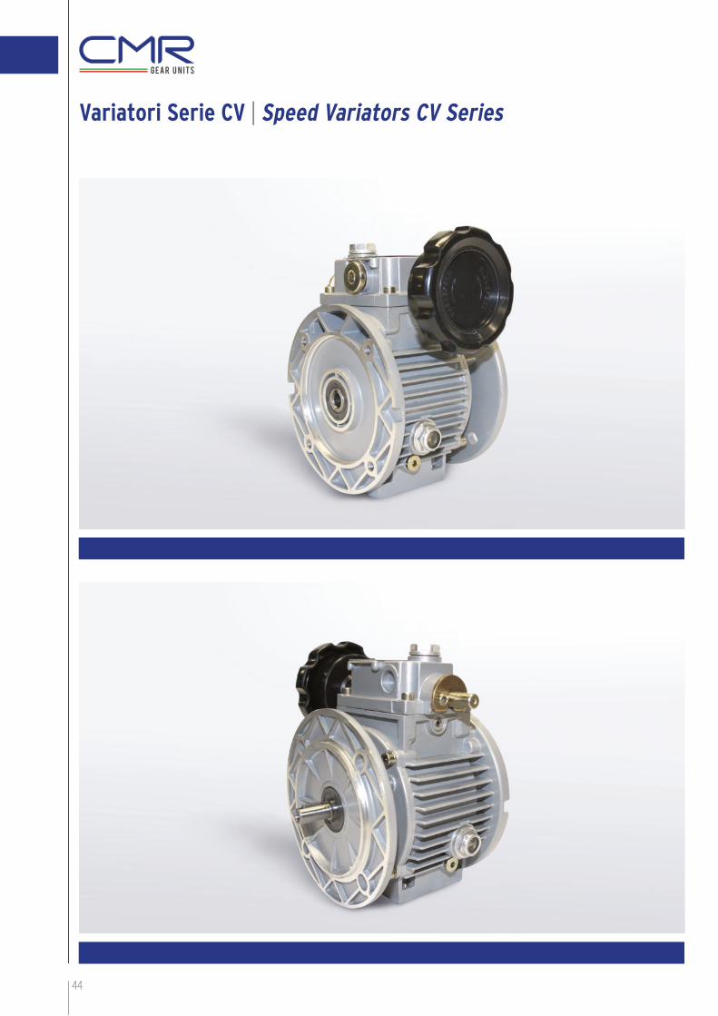
Variatori Serie CV | Speed Variators CV Series
CMRB

Posizione montaggioAssembly position
Posizione morsetteriaTerminal box position
45
CMR presenta la sua linea di variatori meccanici a bagno d’olio
serie CV nelle grandezze 02-05-10, le principali caratteristiche sono
le seguenti:
Campo di variazione 1:5
Funzionamento uniforme e silenzioso
Coppia crescente ai bassi giri
Elevato rendimento
Flange entrata e uscita B5
Forma compatta
Casse in alluminio
Verniciati RAL 9022 grigio
>
>
>
>
>
>
>
>
CMR introduces his mechanical speed variators line with oil bath
lubrifi cation CV series sizes 02-05-10, the main characteristics are
the following:
Speed range 1:5
Smooth and silent running
Increasing torque at low speed
High effi cency
Input and output fl ange B5
Compact design
Aluminium cases
RAL 9022 grey painted
>
>
>
>
>
>
>
>
DESIGNAZIONE | DESIGNATION
TipoType
GrandezzaSize
PotenzaPower
PoliPoles
Tensione Voltage
Frequenza Frequency
Pos.mors. T.box.pos.
Pos.mont. Mount.pos.
CV
02 0,18/0,22 4 230/400 50HZ 1 B5
05 0,37 2 V1
10 0,75 3 V3
0,75 4
Variatori Serie CV | Speed Variators CV Series
A
A
A

46
VariatoreSpeed Variator
Potenza KwPower Kw
Velocità uscitaOutput speed
Coppia uscita NmOutput torque Nm
CV 02 0,18 170 - 880 3 – 1,5
CV 02 0,22 170 - 880 3,8 – 1,9
CV 05 0,37 200 - 1000 6 – 3,0
CV 10 0,75 200 - 1000 12 – 6,0
Quantità olio KgOil quantity Kg
CV 02 05 10
B5 0,131 0,15 0,33
V1 0,3 0,4 0,85
V3 0,2 0,25 0,45
B D(j6) E G G3 H I M M2 N d d1 d2 P T K VC VF VL VR VR1 VS b f t kg
CV02IEC63-B5
23 11 50 112,5 64,5 70 72 115 60 95 9 M8 M6 140 3,5 46 71 111 78 110 110 85 4 M5 12,5 3,4
CV05IEC71-B5
30 14 40 110 74 80 90 130 76 110 9 M8 M8 160 3,5 52,5 71 123 90 110 110 85 5 M6 16 4,7
CV10IEC80-B5
40 19 58 139 85,5 100 98 165 84 130 11 M10 M8 200 3,5 60 79 140 107 120 120 110 6 M6 21,5 7,8
CV 02-05-10 Dimensioni | CV 02-05-10 Dimensions
CV 02-05-10 Caratteristiche con 1400rpm in ingresso | CV 02-05-010 characteristics with input speed 1400rpm
Lubrifi cazioneI variatori vengono forniti completi di lubrifi cazione
per la posizione B5, per le altre posizioni andrà
aggiunto olio come da tabella seguente.
LubricationSpeed variators are supplied with lubrifi cation oil for
assembly position B5, for other positions it will be
necessary to add oil, see following table.
Oli consigliati | Recommended oils AGIP A.T.F. DEXRONESSO A.T.F. DEXRON
SHELL A.T.F. DEXRONBP A.T.F. DEXRON

Lista parti di ricambio | Spare part list
1) Albero di uscita
2) Portasatelliti
3) Boccola scorrevole
4) Pista di regolazione
5) Anello portasfere
6) Pista mobile esterna
7) Satellite
8) Scatola di comando
9) Pista fi ssa esterna
10) Pista fi ssa interna
11) Pista mobile interna
12) Molle a tazza
13) Albero motore
1) Output shaft
2) Placet support
3) Slide block
4) Regulating orbit
5) Ball ring
6) Moving outer planetary orbit
7) Placet wheel
8) Operating box
9) Fixed outer planetary orbit
10) Fixed inferior planetary orbit
11) Moving inferior planetary orbit
12) Butterfl y spring
13) Motor shaft
47
Uso e Manutenzione Use and Maintenance
Le viti di regolazione montate sotto il volantino sono
tarate, non vanno toccate. Non manovrare il volantino
con il motore fermo, può causare rotture interne.
I variatori sono forniti completi di olio, verifi care il
livello prima della messa in funzione. Dopo il rodaggio
sostituire olio, si consiglia di controllare spesso il
livello. La temperatura dopo il rodaggio può arrivare
50/55°C oltre la temperatura ambiente.
Quando il variatore è fornito senza motore accertarsi
che quello da montare sia di classe “normale” e che
l’accoppiamento non sia forzato. I variatori sono
provvisti di tappi di carico chiusi.ì Quando il variatore
viene utilizzato per lavoro continuo. Sostituire il
tappo chiuso con quello di sfi ato in dotazione.
The screw under the handwheel are well adjusted,
don’t touch them. Don’t adjust the handwheel when
the motor is off, this can cause internal breaking.
Speed variators are fi lled with oil, check the level
before running. After the runnig-in the oil must be
changed, check the level periodically.
The temperature after the running-in can reach
50/55°C over room temperature.
When the variator is supplied without motor make
sure that the assembled one is at least “normal” class
quality and the connection is not forced.
Speed variators are supplied sith closed oil plugs.
When the variator is used for continuous work replace.
The closed plug with supplied brearther plug.

48
CMR nel mondo | CMR in the world

49

Bianchi Industrial SpA a Socio Unico
SEDE LEGALE E DIREZIONE GENERALE:
20125 MILANO - Via Zuretti, 100 - Tel. 026786.1 - Fax 026701062
www.bianchi-industrial - [email protected]
CENTRO DISTRIBUZIONE PRODOTTI NAZIONALE:
20091 BRESSO (MI) - Via C. Romani, 25 - Tel. 026786.1 - Fax 0266500235
- bresso @bianchi-
CENTRO DISTRIBUZIONE PRODOTTI REGIONALE:
40132 BOLOGNA - Via Giovanni Elkan, 5 - Tel. 051414849 - Fax 051729301
FILIALI:
20025 LEGNANO (MI) - Via M. Venegoni, 80 - Tel. 0331597762 - Fax 0331545417
25128 BRESCIA - Via della Volta, 181 - Tel. 0305105024 - Fax 0305105022
10098 RIVOLI (TO) - Via Acqui, 51/A - Tel. 011721670 - Fax 011724187
35127 PADOVA - Via Polonia, 21 - Tel. 0498701233 - Fax 0498701209
40132 BOLOGNA - Via Giovanni Elkan, 5 - Tel. - Fax 051729301
60131 ANCONA - Via Albertini, 36/B11 - Tel. 0712861826 - Fax 0712861827
50019 SESTO FIORENTINO (FI) - Via Luciano Lama, 18/20 - Tel. 055319205 - Fax 055319316
63033 MONTEPRANDONE (AP) - Via Scopa, 4 - Tel. 0735705273 - Fax 0735713196
70026 MODUGNO (BA) - Via delle Camelie - Tel. 0805370606 - Fax 0805314551
09122 CAGLIARI - Viale Monastir, 210 - Tel. 070548114 - Fax 070531145
BIANCHI INDUSTRIAL - ItaliaLUIGI BIANCHI SpA - ItaliaRODAMIENTOS FEYC SA - Spagna - PortogalloRJ INTERNATIONAL SAS - FranciaANTIFRICTION COMPONENTS Ltd - UK
051414849
www.bianchi-industrial industrial.it


