SALPA ANCORA VERTICALE Cima e catena su un unico barbotin senza soluzione di continuità A-F 700/1000/1400W VERTICAL WINDLASS Rope and chain on a single gipsy without interruption A-F 700/1000/1400W GUINDEAU VERTICAL Cordage et chaîne sur le même barbotin sans intervalle A-F 700/1000/1400W VERTIKAL ANKERWINDE Ankerseil und Kette auf einer Kombinierten Kettennuß A-F 700/1000/1400W MOLINETE VERTICALE Cavo y cadena en un único barbotín sin solución de continuidad A-F 700/1000/1400W Manuale d’uso User’s Manual Manuel de l’utilisateur Benutzerhandbuch Manual del usuario REV 004 pag. 16 pag. 22 pag. 28 pag. 4 pag. 10
Transcript
SALPA ANCORA VERTICALECima e catena su un unico barbotin senza soluzione di continuitàA-F 700/1000/1400W
VERTICAL WINDLASS Rope and chain on a single gipsywithout interruptionA-F 700/1000/1400W
GUINDEAU VERTICALCordage et chaîne sur le même barbotin sans intervalleA-F 700/1000/1400W
VERTIKAL ANKERWINDEAnkerseil und Kette auf einerKombinierten KettennußA-F 700/1000/1400W
MOLINETE VERTICALECavo y cadena en un único barbotínsin solución de continuidad A-F 700/1000/1400W
Manuale d’uso
User’s Manual
Manuel de l’utilisateur
Benutzerhandbuch
Manual del usuario
REV 004
pag. 16
pag. 22
pag. 28
pag. 4
pag. 10
3
INDICEPag. 4 Caratteristiche tecnichePag. 5 InstallazionePag. 6 Schema di collegamento
INDICEPág. 28 Características técnicasPág. 29 InstalaciónPág. 30 Diagrama de conexions
Pág. 31 UsoPág. 32/33 Mantenimiento
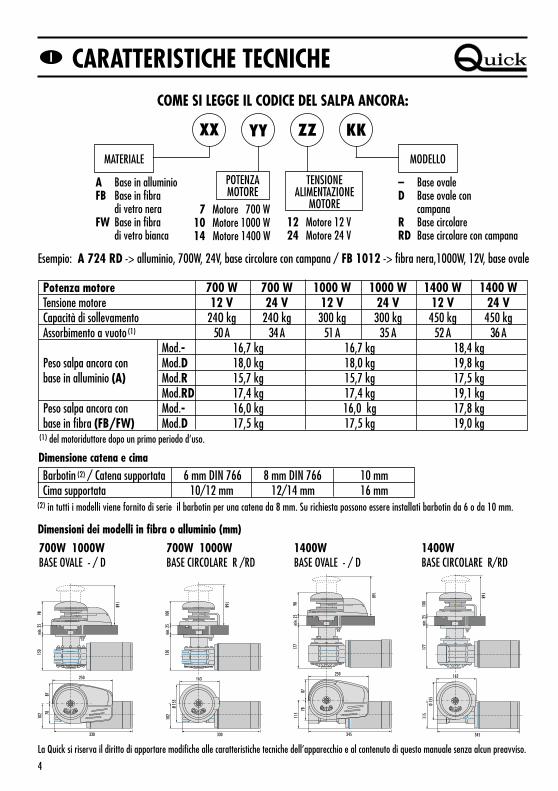
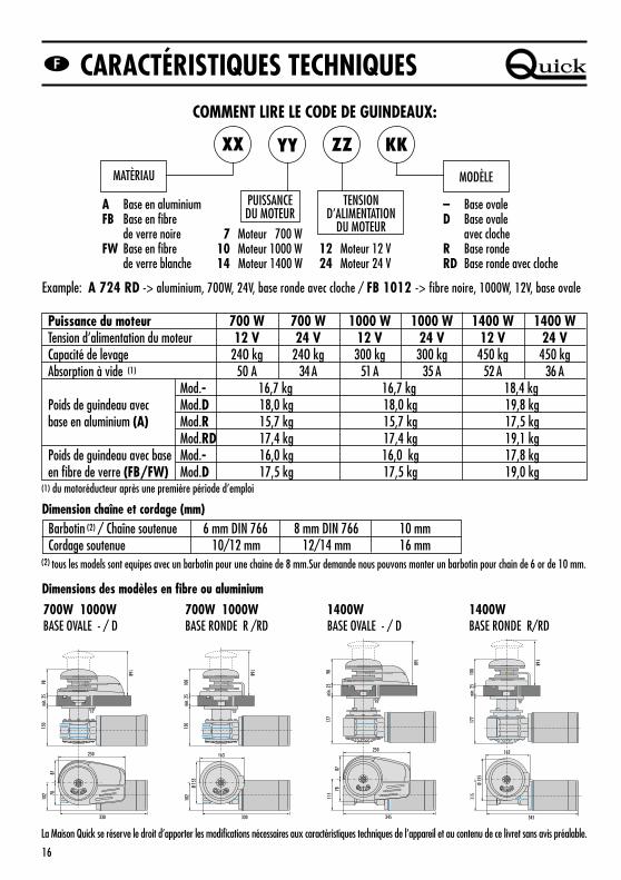
(1) del motoriduttore dopo un primo periodo d’uso.
Potenza motore 700 W 700 W 1000 W 1000 W 1400 W 1400 WTensione motore 12 V 24 V 12 V 24 V 12 V 24 VCapacità di sollevamento 24O kg 24O kg 300 kg 300 kg 450 kg 450 kgAssorbimento a vuoto (1) 50 A 34 A 51 A 35 A 52 A 36 A
Mod.- 16,7 kg 16,7 kg 18,4 kgPeso salpa ancora con Mod.D 18,0 kg 18,0 kg 19,8 kgbase in alluminio (A) Mod.R 15,7 kg 15,7 kg 17,5 kg
Mod.RD 17,4 kg 17,4 kg 19,1 kgPeso salpa ancora con Mod.- 16,0 kg 16,0 kg 17,8 kgbase in fibra (FB/FW) Mod.D 17,5 kg 17,5 kg 19,0 kg
4
COME SI LEGGE IL CODICE DEL SALPA ANCORA:
Esempio: A 724 RD -> alluminio, 700W, 24V, base circolare con campana / FB 1012 -> fibra nera,1000W, 12V, base ovale
700W 1000W BASE OVALE - / D
Dimensioni dei modelli in fibra o alluminio (mm)
700W 1000W BASE CIRCOLARE R /RD
La Quick si riserva il diritto di apportare modifiche alle caratteristiche tecniche dell’apparecchio e al contenuto di questo manuale senza alcun preavviso.
XX YY ZZ KK
MATERIALE
A Base in alluminioFB Base in fibra
di vetro neraFW Base in fibra
di vetro bianca
– Base ovaleD Base ovale con
campanaR Base circolareRD Base circolare con campana
TENSIONE ALIMENTAZIONE
MOTORE
12 Motore 12 V24 Motore 24 V
POTENZAMOTORE
7 Motore 700 W10 Motore 1000 W14 Motore 1400 W
MODELLO
330
min.
25
150
7887
102
250
168
98
min.
25
168
330
150
102
100
163
Ø 15
5
min.
25
168
345
177
115
100
163
Ø 15
5
1400WBASE OVALE - / D
1400WBASE CIRCOLARE R/RD
Barbotin (2) / Catena supportata 6 mm DIN 766 8 mm DIN 766 10 mm Cima supportata 10/12 mm 12/14 mm 16 mm
min.
25
168
345
177
78
115
87
250
98
Dimensione catena e cima
(2) in tutti i modelli viene fornito di serie il barbotin per una catena da 8 mm. Su richiesta possono essere installati barbotin da 6 o da 10 mm.
CARATTERISTICHE TECNICHE
5
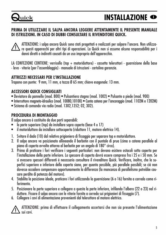
PRIMA DI UTILIZZARE IL SALPA ANCORA LEGGERE ATTENTAMENTE IL PRESENTE MANUALEDI ISTRUZIONI. IN CASO DI DUBBI CONSULTARE IL RIVENDITORE QUICK.
ATTENZIONE: i salpa ancora Quick sono stati progettati e realizzati per salpare l’ancora. Non utilizza-re questi apparecchi per altri tipi di operazioni. La Quick non si assume alcuna responsabilità per idanni diretti o indiretti causati da un uso improprio dell’apparecchio.
LA CONFEZIONE CONTIENE: verricello (top + motoriduttore) - cassetta teleruttori - guarnizione della base - leva - viterie (per l’assemblaggio) - manuale di istruzioni - cartolina garanzia.
ATTREZZI NECESSARI PER L’INSTALLAZIONETrapano con punte: 9 mm, 11 mm, a tazza Ø 65 mm; chiave esagonale: 13 mm.
ACCESSORI QUICK CONSIGLIATI• Deviatore da pannello (mod. 800) • Pulsantiera stagna (mod. 1002) • Pulsante a piede (mod. 900) • Interruttore magneto-idraulico (mod. 10080,10100) • Conta catena per l’ancoraggio (mod. 1102M e 1202M) • Sistema di comando via radio (mod. 1302,1352; 02, 302).
PROCEDURA DI MONTAGGIOIl salpa ancora è costituito da due parti separabili:• la parte superiore (top) da installare sopra coperta (base 4 o 17)• il motoriduttore da installare sottocoperta (riduttore 11, motore elettrico 14).
1. Svitare il dado (10) dal relativo prigioniero di fissaggio per separare top e motoriduttore.2. Il salpa ancora va posizionato allineando il barbotin con il puntale di prua (cima o catena parallele al
piano di coperta avvolte attorno al barbotin per un angolo di 180° circa).3. Prima di praticare i fori verificare i seguenti particolari: non devono esistere ostacoli sotto coperta per
l’installazione della parte inferiore. Lo spessore di coperta dovrà essere compreso fra i 25 e i 50 mm. Sesi avessero spessori differenti è necessario consultare il rivenditore Quick. Verificare, inoltre, che le su-perfici superiore e inferiore della coperta siano, per quanto possibile, più parallele possibili; se ciò nondovesse accadere compensare opportunamente la differenza (la mancanza di parallelismo potrebbe cau-sare perdite di potenza del motore).
4. Stabilita la posizione ideale, praticare i fori utilizzando la guarnizione (6 o 16) fornita a corredo come ri-ferimento.
5. Posizionare la parte superiore e collegare a questa la parte inferiore, infilando l’albero (22 o 23) nel ri-duttore. Fissare il salpa ancora con le viterie fornite a corredo sui prigionieri di fissaggio (7).
6. Collegare i cavi di alimentazione provenienti dal teleruttore al motore elettrico.
ATTENZIONE: prima di effettuare il collegamento accertarsi che non sia presente l’alimentazionesui cavi.
INSTALLAZIONE
6
- +
M1
M2
I TI T A LA L YY
1 2
1 2
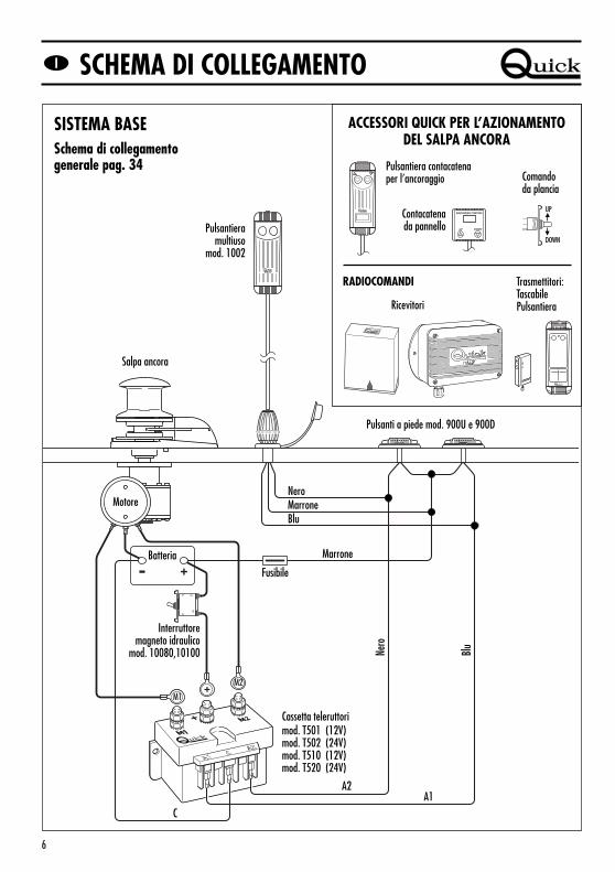
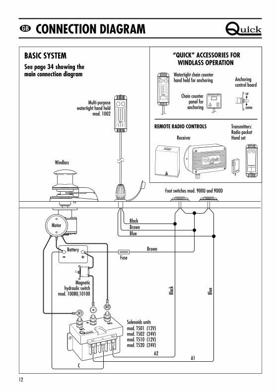
ACCESSORI QUICK PER L’AZIONAMENTO DEL SALPA ANCORA
RADIOCOMANDI
Contacatenada pannello
Comando da plancia
UP
DOWN
SISTEMA BASESchema di collegamentogenerale pag. 34 Pulsantiera contacatena
ATTENZIONE: non avvicinare parti del corpo o oggetti alla zona in cui scorrono catena, cima e barbo-tin. Accertarsi che non sia presente l’alimentazione al motore elettrico quando si opera manualmentesul salpa ancora (anche quando si utilizza la leva per allentare la frizione); infatti persone dotate dicomando a distanza del salpa ancora (pulsantiera remota o radiocomando) potrebbero accidental-mente attivarlo.
ATTENZIONE: bloccare la catena con un fermo prima di partire per la navigazione.
ATTENZIONE: non attivare elettricamente il salpa ancora con la leva inserita nella campana o nel co-perchio del barbotin.
USO DELLA FRIZIONEIl barbotin è reso solidale all’albero principale (22 o 23) dalla frizione (29). La frizione si apre (stacco) utiliz-zando la leva (35) che inserita nella bussola della campana o coperchio barbotin (34 o 32) dovrà ruotare insenso antiorario. Ruotando in senso orario si provocherà la chiusura (attacco) della frizione.
PER SALPAREAccendere il motore dell’imbarcazione. Assicurarsi che la frizione sia serrata ed estrarre la leva. Premere ilpulsante UP del comando a vostra disposizione. Se il salpa ancora si arresta senza che l’interruttore magne-to-idraulico (o magnetotermico) sia scattato, attendere qualche secondo e riprovare (evitare una pressionecontinuata del pulsante). Se l’interruttore magneto-idraulico (o magnetotermico) è scattato, riattivare l’inter-ruttore e attendere qualche minuto prima di riprendere a salpare. Se, dopo ripetuti tentativi, il salpa ancoracontinua a bloccarsi consigliamo di manovrare l’imbarcazione per disincagliare l’ancora.Controllare la salita degli ultimi metri di catena per evitare danni alla prua.
PER CALARELa calata dell’ancora si può effettuare tramite comandi elettrici oppure manualmente. Per effettuare l’opera-zione manualmente occorre aprire la frizione lasciando libero il barbotin di girare sul proprio asse e trascina-re la catena o la cima in acqua. Per frenare la caduta dell’ancora bisogna ruotare la leva in senso orario.Per calare l’ancora elettricamente occorre premere il pulsante DOWN del comando a vostra disposizione. Inquesto modo la calata è perfettamente controllabile e lo svolgimento della catena o della cima è regolare.Per evitare sollecitazioni sul salpa ancora, una volta ancorati, bloccare la catena con un fermo oppure fissarlaad un punto saldo con una cima.
USO
8
1920
13
7
7
12
21
10
8
9
11
1
2
3
4
5
6
35
18
33
32
29
31
30
29
23
29
31
30
29
22
34
17
16
21
14
36
24
25
24
26
27
28
24
25
24
26
27
28
15
18
37
38
39
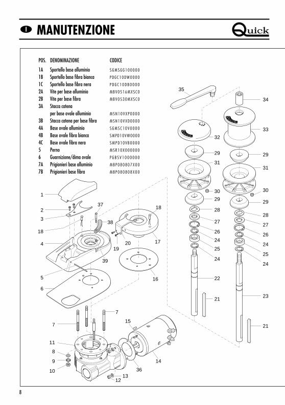
MANUTENZIONE
POS. DENOMINAZIONE CODICE
1A Sportello base alluminio S G M S G G 1 0 0 0 0 0
1B Sportello base fibra bianca P D G C 1 0 D W 0 0 0 0
1C Sportello base fibra nera P D G C 1 0 D B 0 0 0 0
2A Vite per base alluminio MBV0516MXSC0
2B Vite per base fibra MBV0530MXSC0
3A Stacca catena per base ovale alluminio M S N 1 0 V X P 0 0 0 0
3B Stacca catena per base fibra M S N 1 0 V X D 0 0 0 0
4A Base ovale alluminio S G M S C 1 0 V 0 0 0 0
4B Base ovale fibra bianca SMPD10VW0000
4C Base ovale fibra nera S M P D 1 0 V B 0 0 0 0
5 Perno M S R 1 0 X 0 0 0 0 0 0
6 Guarnizione/dima ovale P G B S V 1 0 0 0 0 0 0
7A Prigionieri base alluminio M B P 0 8 0 8 0 7 X 0 0
7B Prigionieri base fibra M B P 0 8 0 8 0 8 X 0 0
9
ATTENZIONE: accertarsi che non sia presente l’ali-mentazione al motore elettrico quando si operamanualmente sul salpa ancora; rimuovere concura la catena o cima dal barbotin o la cima dallacampana.
I salpa ancora Quick sono costituiti da materiali resistentiall’ambiente marino: è indispensabile, in ogni caso, rimuo-vere periodicamente i depositi di sale che si formano sullesuperfici esterne per evitare corrosioni e di conseguenzadanni all’apparecchio.Lavare accuratamente con acqua dolce le superfici e leparti in cui il sale può depositarsi.
Smontare una volta all’anno il barbotin e la campana atte-nendosi alla seguente sequenza:
Versione con campanaCon la leva (35) svitare la bussola (34); estrarre la cam-pana (33) e il cono frizione superiore (29); svitare le vitidi fissaggio (2 o19) dello stacca catena (3 o 20) e rimuo-verlo; estrarre il barbotin (31).
Versione senza campanaCon la leva (35) svitare il coperchio barbotin (32);estrarre il cono frizione superiore (29); svitare le viti difissaggio (2 o 19) dello stacca catena (3 o 20) e rimuo-verlo; estrarre il barbotin (31).
Pulire ogni parte smontata affinché non si verifichino at-tacchi di corrosione e ingrassare (con grasso marino) il fi-letto dell’albero (22 o 23) e il barbotin (31) dove appog-giano i coni frizione (29).
Ingrassare periodicamente il perno (5) dello sportello diispezione (solamente per salpa ancora con base in allu-minio).
Rimuovere eventuali depositi di ossido sui morsetti di ali-mentazione del motore elettrico e su quelli della cassettateleruttori; cospargerli di grasso.
ATTENZIONE: il motore elettrico del salpa ancoranon è stagno; resiste a spruzzi di acqua ma non aimmersioni.
MANUTENZIONE
POS. DENOMINAZIONE CODICE
8 Rondelle M B R 0 8 X 0 0 0 0 0 0
9 Rondella dentellata M B R 0 8 X D E 0 0 0 0
10 Dado MBD08MXEN000
11A Riduttore 700-1000W M R 1 0 0 0 0 0 0 0 0 0
11B Riduttore 1400W M R 1 4 0 0 0 0 0 0 0 0
12 Dado autobloccante M B D 0 6 M X E T 0 0 0
13 Rondella M B R 0 6 1 8 1 5 X 0 0
14A Motore 700W 12V E M F 0 7 1 2 0 0 0 0 0
14B Motore 700W 24V E M F 0 7 2 4 0 0 0 0 0
14C Motore 1000W 12V E M F 1 0 1 2 0 0 0 0 0
14D Motore 1000W 24V E M F 1 0 2 4 0 0 0 0 0
14E Motore 1400W 12V Z S M 1 4 1 2 0 0 0 0 0
14F Motore 1400W 24V Z S M 1 4 2 4 0 0 0 0 0
15 Chiavetta M B H 0 5 0 5 1 5 F 0 0
16 Guarnizione/dima circolare P G B S C 1 0 0 0 0 0 0
17 Base circolare S G M S C 1 0 C 0 0 0 0
18 Sensore S A K R E E D 0 0 0 0 0
19 Vite MBV0520MXSC0
20 Stacca catena per base circolare M S N 1 0 C X 0 0 0 0 0
21 Chiavetta M B H 0 8 0 7 8 0 F 0 0
22 Albero corto M S A S 1 0 2 7 4 R 1 0
23 Albero lungo M S A S 1 0 3 0 8 R 0 0
24 Anello elastico esterno M B A E 2 5 2 0 Y 0 0 0
25 Cuscinetto M B J 6 0 0 5 2 R S 1 0
26 Anello elastico interno M B A N 4 7 1 7 Y 0 0 0
27 Paraolio P G P R L 2 5 4 7 7 0 0
28 Rondella sagomata M B R 2 5 4 0 2 5 X 0 0
29 Cono frizione M S F 1 0 0 0 0 0 0 0 0
30 Magnete K P M C 0 8 0 6 0 0 0 0
31A Barbotin 6mm Z S B 1 0 0 6 0 0 0 0 0
31B Barbotin 8mm-5/16" Z S B 1 0 0 8 5 1 6 0 0
31C Barbotin 10mm-3/8" Z S B 1 0 1 0 3 8 0 0 0
32 Coperchio barbotin S G M S G B 1 0 0 0 0 0
33 Campana Z S G M S E 1 0 0 0 0 0
34 Bussola S G M S D 1 0 0 0 0 0 0
35A Leva 700-1000W M S M V T 0 4 0 0 0 0 0
35B Leva 1400W Z S L M S H 0 0 0 0 0 0
36 Guarnizione carta P G B M R 1 0 0 0 0 0 0
37 Vite tendicima M S M V T 1 0 0 0 0 0 0
38A Leva tendicima nera P D L V T D 1 0 0 0 0 0
38B Leva tendicima bianca P D LV T D 1 0 W 0 0 0
39 Molla tendicima MMTND1000000
10
TECHNICAL DATAHOW TO IDENTIFY THE WINDLASS THROUGH THE CODE:
Example: A 724 RD -> aluminium, 700 W, 24 V, round base with drum / FB 1012 -> black fiber, 1000 W, 12V, oval base
(1) of the geared motor after the initial period of operation
“Quick” reserves the right to introduce changes to the equipment and the contents of this manual without prior notice.
XX YY ZZ KK
MATERIAL
A Aluminium baseFB Black
fiber-glass baseFW White
fiber-glass base
– Oval baseD Oval base with
drumR Round baseRD Round base with drum
MOTOR SUPPLYVOLTAGE
12 Motor 12 V24 Motor 24 V
MOTOROUTPUT
7 Motor 700 W10 Motor 1000 W14 Motor 1400 W
MODEL
Motor output 700 W 700 W 1000 W 1000 W 1400 W 1400 WMotor supply voltage 12 V 24 V 12 V 24 V 12 V 24 VWorking load 24O kg 24O kg 300 kg 300 kg 450 kg 450 kgAbsorption under no-load condition (1) 50 A 34 A 51 A 35 A 52 A 36 A
Mod.- 16,7 kg 16,7 kg 18,4 kgAluminium base windlass Mod.D 18,0 kg 18,0 kg 19,8 kgweight (A) Mod.R 15,7 kg 15,7 kg 17,5 kg
Mod.RD 17,4 kg 17,4 kg 19,1 kgFiber glass windlass Mod.- 16,0 kg 16,0 kg 17,8 kgweight (FB/FW) Mod.D 17,5 kg 17,5 kg 19,0 kg
Rope and chain size
(2) all models are equipped with a gipsy for 8 mm chain.On request we can mount a gipsy for a 6 or 10 mm chain.
Gipsy (2) / Chain size 6 mm DIN 766 8 mm DIN 766 10 mmRope size 10/12 mm 12/14 mm 16 mm
700W 1000W OVAL BASE - / D
Dimensions of models in aluminium or fiberglass (mm)
700W 1000W ROUND BASE R /RD
330
min.
25
150
7887
102
250
168
98
min.
25
168
330
150
102
100
163
Ø 15
5
min.
25
168
345
177
115
100
163
Ø 15
5
1400WOVAL BASE - / D
1400WROUND BASE R/RD
min.
25
168
345
177
78
115
87
250
98
11
INSTALLATIONBEFORE USING THE WINDLASS READ THESE INSTRUCTIONS CAREFULLY.IF IN DOUBT, CONTACT YOUR NEAREST “QUICK” DEALER.
WARNING: the QUICK windlasses are designed to weigh the anchor. Do not use the equipments forother purposes. QUICK shall not be held responsible for damage to equipment and/or personalinjury, caused by a faulty use of the equipment.
THE PACKAGE CONTAINS: windlass (on deck unit + geared motor) - reversing solenoid unit - base gasket - Handle - bolts and screws (for assembly) - user’s manual - warranty card.
TOOLS REQUIRED FOR INSTALLATIONDrill and drill bits: 9 mm, 11 mm, 65 mm Ø hollow mill; hex. wrenches: 13 mm
“QUICK”ACCESSORIES RECOMMENDED• Anchoring RL control board (mod. 800) • Waterproof hand helds R/C (mod. 1002) • Foot switch (mod. 900) • Hydraulic-magnetic switch (mod. 10080,10100) • Anchor chain counter (mod. 1102M and 1202M) • Radio control (mod. 1302,1352; 02, 302).
ASSEMBLY PROCEDURE The windlass is made up of two separate parts:• the upper part is to be installed on deck (base 4 or 17) • geared motor is to be installed below deck (gearbox 11, electric motor 14).
1. Remove the nut (10) from the stud to take apart the on deck unit from gear box.2. The windlass has to be placed in position by aligning the gypsy with the bow point (rope or chain leveled
with the deck and wound around the gypsy at an angle of about 180°).3. Before drilling holes, check the following:there are to be no obstacles below deck in order to install the
bottom part. Deck thickness must range between 25 and 50 mm; for a different thickness, contact yournearest QUICK dealer. Also make sure the top and bottom surfaces of the deck are as parallel as possible;if necessary, compensate for any differences (if not parallel, the motor power may drop)
4. Once the ideal position has been found, drill the holes using the jig (6 or 15) supplied. 5. Place the upper part in position and connect it to the bottom part. Fit the shaft (21 or 23) into the
gearbox. Secure the windlass by using the studs (7) and the screws supplied. 6. Connect the power cables coming from the reversing solenoid unit to the electric motor.
WARNING: before wiring up, be sure the electrical cables are not live.
WARNING: stay clear of the chains, ropes and gypsy. Make sure the electric motor is off when wind-lass is used manually (even when using the handle for disengaging the clutch). In fact people with aremote control (remote control or control system via radio) might accidentally operate the windlass.
WARNING: secure the chain with a device before starting the navigation.
WARNING: do not operate the windlass by using the electrical power when the handle is inserted inthe drum or into the gypsy cover.
CLUTCH USEThe clutch (29) provides a link between the gypsy and the main shaft (22 or 23). The clutch can be released(disengagement) by using the handle (35) which, when inserted in the drum or in the gypsy cover (34 or32), must be turned counter-clockwise. The clutch will be re-engaged by turning it clockwise.
WEIGHING THE ANCHOR Turn on the engine. Make sure the clutch is engaged and remove the handle. Press the UP button on the con-trol provided. If the windlass stops and the hydraulic magnetic switch (or thermal cutout) has not tripped,wait a few seconds and try again (avoid keeping the button pressed). If the hydraulic magnetic switch, hastripped, reset it and wait a few minutes before weighing anchor once again. If, after a number of attempts,the windlass is still blocked, we suggest to move the boat to release the anchor. Check the upward movementof the chain for the last few meters in order to avoid damages to the bow.
CASTING THE ANCHOR The anchor can be cast by using the electrical control or manually. To operate manually, the clutch must be di-sengaged allowing the gypsy to revolve and letting the rope or chain fall into the water. To slow down thechain, the handle must be turned clockwise. To cast the anchor by using the electrical power, press the DOWN button on the control provided. In this man-ner, anchor casting is under control and the chain and rope unwind evenly. In order to avoid any stress on the windlass -once the boat is anchored- fasten the chain or secure it in placewith a rope.
14
1920
13
7
7
12
21
10
8
9
11
1
2
3
4
5
6
35
18
33
32
29
31
30
29
23
29
31
30
29
22
34
17
16
21
14
36
24
25
24
26
27
28
24
25
24
26
27
28
15
18
37
38
39
MAINTENANCE
POS. DESCRIPTION CODE
1A Inspection lid aluminium base S G M S G G 1 0 0 0 0 0
1B Inspection lidwhite fiber-glass base P D G C 1 0 D W 0 0 0 0
1C Inspection lidblack fiber-glass base P D G C 1 0 D B 0 0 0 0
2A Screw aluminium base MBV0516MXSC0
2B Screw fiber-glass base MBV0530MXSC0
3A Rope/chain stripper oval base M S N 1 0 V X P 0 0 0 0
3B Rope/chain stripper fiber-glass base M S N 1 0 V X D 0 0 0 0
4A Oval base aluminium S G M S C 1 0 V 0 0 0 0
4B Oval base white fiber-glass SMPD10VW0000
4C Oval base black fiber-glass S M P D 1 0 V B 0 0 0 0
5 Pin M S R 1 0 X 0 0 0 0 0 0
6 Gasket/oval-shaped jig P G B S V 1 0 0 0 0 0 0
15
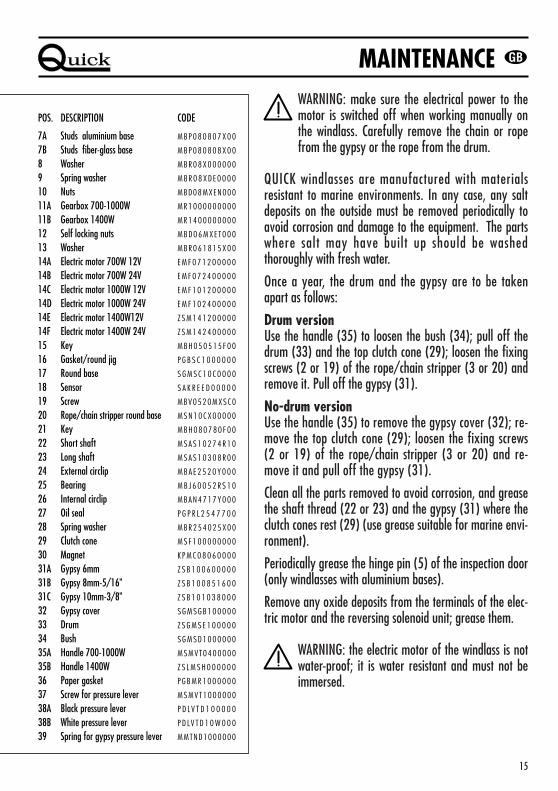
WARNING: make sure the electrical power to themotor is switched off when working manually onthe windlass. Carefully remove the chain or ropefrom the gypsy or the rope from the drum.
QUICK windlasses are manufactured with materialsresistant to marine environments. In any case, any saltdeposits on the outside must be removed periodically toavoid corrosion and damage to the equipment. The partswhere salt may have built up should be washedthoroughly with fresh water.
Once a year, the drum and the gypsy are to be takenapart as follows:
Drum versionUse the handle (35) to loosen the bush (34); pull off thedrum (33) and the top clutch cone (29); loosen the fixingscrews (2 or 19) of the rope/chain stripper (3 or 20) andremove it. Pull off the gypsy (31).
No-drum versionUse the handle (35) to remove the gypsy cover (32); re-move the top clutch cone (29); loosen the fixing screws(2 or 19) of the rope/chain stripper (3 or 20) and re-move it and pull off the gypsy (31).
Clean all the parts removed to avoid corrosion, and greasethe shaft thread (22 or 23) and the gypsy (31) where theclutch cones rest (29) (use grease suitable for marine envi-ronment).
Periodically grease the hinge pin (5) of the inspection door(only windlasses with aluminium bases).
Remove any oxide deposits from the terminals of the elec-tric motor and the reversing solenoid unit; grease them.
WARNING: the electric motor of the windlass is notwater-proof; it is water resistant and must not beimmersed.
MAINTENANCE
POS. DESCRIPTION CODE
7A Studs aluminium base M B P 0 8 0 8 0 7 X 0 0
7B Studs fiber-glass base M B P 0 8 0 8 0 8 X 0 0
8 Washer M B R 0 8 X 0 0 0 0 0 0
9 Spring washer M B R 0 8 X D E 0 0 0 0
10 Nuts MBD08MXEN000
11A Gearbox 700-1000W M R 1 0 0 0 0 0 0 0 0 0
11B Gearbox 1400W M R 1 4 0 0 0 0 0 0 0 0
12 Self locking nuts M B D 0 6 M X E T 0 0 0
13 Washer M B R 0 6 1 8 1 5 X 0 0
14A Electric motor 700W 12V E M F 0 7 1 2 0 0 0 0 0
14B Electric motor 700W 24V E M F 0 7 2 4 0 0 0 0 0
14C Electric motor 1000W 12V E M F 1 0 1 2 0 0 0 0 0
14D Electric motor 1000W 24V E M F 1 0 2 4 0 0 0 0 0
14E Electric motor 1400W12V Z S M 1 4 1 2 0 0 0 0 0
14F Electric motor 1400W 24V Z S M 1 4 2 4 0 0 0 0 0
15 Key M B H 0 5 0 5 1 5 F 0 0
16 Gasket/round jig P G B S C 1 0 0 0 0 0 0
17 Round base S G M S C 1 0 C 0 0 0 0
18 Sensor S A K R E E D 0 0 0 0 0
19 Screw MBV0520MXSC0
20 Rope/chain stripper round base M S N 1 0 C X 0 0 0 0 0
21 Key M B H 0 8 0 7 8 0 F 0 0
22 Short shaft M S A S 1 0 2 7 4 R 1 0
23 Long shaft M S A S 1 0 3 0 8 R 0 0
24 External circlip M B A E 2 5 2 0 Y 0 0 0
25 Bearing M B J 6 0 0 5 2 R S 1 0
26 Internal circlip M B A N 4 7 1 7 Y 0 0 0
27 Oil seal P G P R L 2 5 4 7 7 0 0
28 Spring washer M B R 2 5 4 0 2 5 X 0 0
29 Clutch cone M S F 1 0 0 0 0 0 0 0 0
30 Magnet K P M C 0 8 0 6 0 0 0 0
31A Gypsy 6mm Z S B 1 0 0 6 0 0 0 0 0
31B Gypsy 8mm-5/16" Z S B 1 0 0 8 5 1 6 0 0
31C Gypsy 10mm-3/8" Z S B 1 0 1 0 3 8 0 0 0
32 Gypsy cover S G M S G B 1 0 0 0 0 0
33 Drum Z S G M S E 1 0 0 0 0 0
34 Bush S G M S D 1 0 0 0 0 0 0
35A Handle 700-1000W M S M V T 0 4 0 0 0 0 0
35B Handle 1400W Z S L M S H 0 0 0 0 0 0
36 Paper gasket P G B M R 1 0 0 0 0 0 0
37 Screw for pressure lever M S M V T 1 0 0 0 0 0 0
38A Black pressure lever P D L V T D 1 0 0 0 0 0
38B White pressure lever P D LV T D 1 0 W 0 0 0
39 Spring for gypsy pressure lever MMTND1000000
Barbotin (2) / Chaîne soutenue 6 mm DIN 766 8 mm DIN 766 10 mmCordage soutenue 10/12 mm 12/14 mm 16 mm
Puissance du moteur 700 W 700 W 1000 W 1000 W 1400 W 1400 WTension d’alimentation du moteur 12 V 24 V 12 V 24 V 12 V 24 VCapacité de levage 24O kg 24O kg 300 kg 300 kg 450 kg 450 kgAbsorption à vide (1) 50 A 34 A 51 A 35 A 52 A 36 A
Mod.- 16,7 kg 16,7 kg 18,4 kgPoids de guindeau avec Mod.D 18,0 kg 18,0 kg 19,8 kgbase en aluminium (A) Mod.R 15,7 kg 15,7 kg 17,5 kg
Mod.RD 17,4 kg 17,4 kg 19,1 kgPoids de guindeau avec base Mod.- 16,0 kg 16,0 kg 17,8 kgen fibre de verre (FB/FW) Mod.D 17,5 kg 17,5 kg 19,0 kg
16
COMMENT LIRE LE CODE DE GUINDEAUX:
Example: A 724 RD -> aluminium, 700W, 24V, base ronde avec cloche / FB 1012 -> fibre noire, 1000W, 12V, base ovale
(1) du motoréducteur après une première période d’emploi
La Maison Quick se réserve le droit d’apporter les modifications nécessaires aux caractéristiques techniques de l’appareil et au contenu de ce livret sans avis préalable.
XX YY ZZ KK
MATÈRIAU
A Base en aluminiumFB Base en fibre
de verre noireFW Base en fibre
de verre blanche
– Base ovaleD Base ovale
avec clocheR Base rondeRD Base ronde avec cloche
TENSION D’ALIMENTATION
DU MOTEUR
12 Moteur 12 V24 Moteur 24 V
PUISSANCEDU MOTEUR
7 Moteur 700 W10 Moteur 1000 W14 Moteur 1400 W
MODÈLE
Dimension chaîne et cordage (mm)
(2) tous les models sont equipes avec un barbotin pour une chaine de 8 mm.Sur demande nous pouvons monter un barbotin pour chain de 6 or de 10 mm.
700W 1000W BASE OVALE - / D
Dimensions des modèles en fibre ou aluminium
700W 1000W BASE RONDE R /RD
330
min.
25
150
7887
102
250
168
98
min.
25
168
330
150
102
100
163
Ø 15
5
min.
25
168
345
177
115
100
163
Ø 15
5
1400WBASE OVALE - / D
1400WBASE RONDE R/RD
min.
25
168
345
177
78
115
87
250
98
CARACTÉRISTIQUES TECHNIQUES
17
AVANT D’UTILISER LE GUINDEAU, LIRE ATTENTIVEMENT CE LIVRET D’INSTRUCTIONS.EN CAS DE DOUTES, S’ADRESSER AU REVENDEUR QUICK.
ATTENTION: les guindeaux Quick ont été projetés et construits pour lever l’ancre. Ne pas utiliser cesappareils pour effectuer d’autres types d’opérations. La Maison Quick n’assume aucune responsabilitépour les dommages directs ou indirects causés par un mauvais emploi de l’appareil.
L’EMBALLAGE COMPREND: guindeau (partie supérieure + motoréducteur) - boîte avec télérupteur - joint de labase - levier - différentes vis (pour l’assemblage) - livret d’instructions - carte-garantie.
OUTILS NECESSAIRES POUR L’INSTALLATIONPerceuse avec mèches: 9 mm, 11 mm, à gorge Ø 65 mm; clés mâle pour vis à six pans creux: 13 mm.
ACCESSOIRES QUICK RECOMMANDES• Interrupteur sur panneau (mod. 800) • Telecommande étanche (mod. 1002) • Bouton à pied (mod. 900)• Disjoncteur magnétique-hydraulique (mod. 10080,10100) • Compteur de chaîne pour l’ancrage(mod.1102M et 1202M • Système de commande par radio (mod. 1302,1352; 02, 302).
PROCEDURE DE MONTAGELe guindeau est constitué de deux parties séparées l’une de l’autre:
• la partie supérieure (top) à installer sur le pont (base 4 ou 17)• le motoréducteur à installer à l’intérieur (réducteur 11, moteur électrique 14).
1. Desserrer l’écrou (10) du goujon de fixation pour séparer la partie supérieure et le motoréducteur.2. Pour positionner le guindeau, aligner le barbotin par rapport au creux d’avant (cordage ou chaîne paral-
lèle à la surface du pont enroulés autour du barbotin pour un angle de 180° environ).3. Avant d’effectuer les ouvertures, contrôler les détails suivants: il ne doit pas y avoir d’obstacles sous le
pont pour l’installation de la partie inférieure. L’épaisseur du pont devra être comprise entre 25 et 50mm. En cas d’épaisseurs différentes, s’adresser au revendeur Quick. Vérifier également si les surfacessupérieure et inférieure du pont sont autant que possible parallèles. Dans le cas contraire, compenser ladifférence (le manque de parallélisme pourrait provoquer une perte de puissance du moteur).
4. Une fois que la position idéale a été établie, pratiquer les ouvertures en utilisant le joint (6 ou 16) fourniavec l’appareil comme référence.
5. Positionner la partie supérieure et relier à celle-ci la partie inférieure en enfilant l’arbre (22 ou 23) dansle réducteur. Fixer le guindeau à l’aide des vis fournies sur les goujons de fixation (7).
6. Connecter les câbles d’alimentation provenant du télérupteur au moteur électrique.
ATTENTION: avant d’effectuer la connexion, contrôler que les câbles ne soient pas alimentés électri-quement.
INSTALLATION
SCHEMA DE CABLAGE
- +
M1
M2
I TI T A LA L YY
1 2
1 2
ACCESSOIRES QUICK POUR ACTIONNER LE GUINDEAU
RADIOCOMMANDES
Compteurde chaîne sur
tableau
Commande du tableau
UP
DOWN
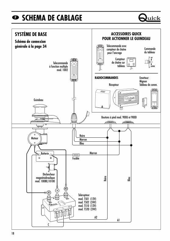
SYSTÈME DE BASESchéma de connexiongénérale à la page 34 Telecommande avec
ATTENTION: ne pas s’approcher de la zone où glissent la chaîne, le cordage et le barbotin. Contrôlerque le moteur ne soit pas alimenté électriquement quand on travaille manuellement sur le guindeau(même quand on utilise le levier pour desserrer l’embrayage); en effet, les personnes munies decommande à distance pour le guindeau (tableau des boutons-poussoirs télé-commandé ou radio-com-mandé) pourraient l’activer involontairement.
ATTENTION: fixer la chaîne avec un disp. d’arrêt avant de partir pour la navigation.
ATTENTION: ne pas activer électriquement le guindeau avec le levier introduit dans la cloche ou dansle couvercle du barbotin.
UTILISATION DE L’EMBRAYAGELe barbotin est solidaire de l’arbre principal (22 ou 23) de l’embrayage (29). L’embrayage s’ouvre à l’aidedu levier (35) qui, une fois introduit dans la douille de la cloche ou dans le couvercle du barbotin (34 ou 32),devra tourner dans le sens contraire aux aiguilles de la montre. Si l’on tourne dans le sens des aiguilles d’unemontre, l’embrayage se fermera.
POUR LEVER L’ANCREAllumer le moteur de l’embarcation. S’assurer si l’embrayage est bien serré et tirer le levier. Presser le bou-ton UP de la commande à votre disposition. Si le guindeau s’arrête sans que le disjoncteur magnéto-hydrauli-que (ou magnéto-thermique) se soit déclenché, attendre quelques secondes et ré-essayer (éviter de presser lebouton en continu). Si le disjoncteur magnéto-thermique s’est déclenché, réactiver le disjoncteur et attendrequelques minutes avant de reprendre l’opération. Si, après plusieurs tentatives, le guindeau continue à sebloquer, nous recommandons d’effectuer des manoeuvres avec l’embarcation pour désensabler l’ancre.Contrôler la montée des derniers mètres de chaîne pour éviter des dommages à l’avant de l’embarcation.
POUR JETER L’ANCREIl est possible de jeter l’ancre par l’intermédiaire des commandes électriques ou bien manuellement. Pour ef-fectuer l’opération manuellement, ouvrir l’embrayage en laissant que le barbotin puisse tourner sur son pro-pre axe et traîner la chaîne ou le cordage dans l’eau. Pour freiner la descente de l’ancre, tourner le levierdans le sens des aiguilles d’une montre.Pour jeter l’ancre électriquement, presser le bouton DOWN de la commande à votre disposition. De cette ma-nière-là, la descente peut être bien contrôlée et le déroulement de la chaîne ou du cordage est régulier.Pour éviter tout effort sur le guindeau, une fois que l’on est ancrés, bloquer la chaîne avec un disp. d’arrêtou bien la fixer à un point solide avec un bout.
UTILISATION
20
1920
13
7
7
12
21
10
8
9
11
1
2
3
4
5
6
35
18
33
32
29
31
30
29
23
29
31
30
29
22
34
17
16
21
14
36
24
25
24
26
27
28
24
25
24
26
27
28
15
18
37
38
39
ENTRETIEN
POSIT. DENOMINATION CODE
1A Porte d’inspection base en aluminium S G M S G G 1 0 0 0 0 0
1B Porte d’inspectionen fibre de verre blanche P D G C 1 0 D W 0 0 0 0
1C Porte d’inspectionen fibre de verre noire P D G C 1 0 D B 0 0 0 0
2A Vis pour base en aluminium MBV0516MXSC0
2B Vis pour base en fibre de verre MBV0530MXSC0
3A Dispositif de détachement de chaîne base ovale M S N 1 0 V X P 0 0 0 0
3B Dispositif de détachement de chaîne base fibre M S N 1 0 V X D 0 0 0 0
4A Base ovale aluminium S G M S C 1 0 V 0 0 0 0
4B Base ovale fibre de verre blanche SMPD10VW0000
4C Base ovale fibre de verre noire S M P D 1 0 V B 0 0 0 0
5 Cheville M S R 1 0 X 0 0 0 0 0 0
6 Joint/gabarit ovale P G B S V 1 0 0 0 0 0 0
21
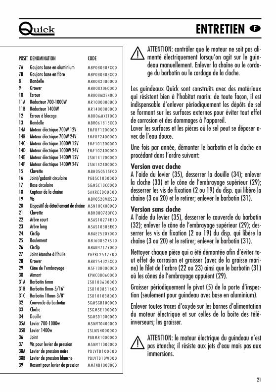
ATTENTION: contrôler que le moteur ne soit pas ali-menté électriquement lorsqu’on agit sur le guin-deau manuellement. Enlever la chaîne ou le corda-ge du barbotin ou le cordage de la cloche.
Les guindeaux Quick sont construits avec des matériauxqui résistent bien à l’habitat marin: de toute façon, il estindispensable d’enlever périodiquement les dépôts de selse formant sur les surfaces externes pour éviter tout effetde corrosion et des dommages à l’appareil.Laver les surfaces et les pièces où le sel peut se déposer a-vec de l’eau douce.
Une fois par année, démonter le barbotin et la cloche enprocédant dans l’ordre suivant:
Version avec clocheA l’aide du levier (35), desserrer la douille (34); enleverla cloche (33) et le cône de l’embrayage supérieur (29);desserrer les vis de fixation (2 ou 19) du disp. qui libère lachaîne (3 ou 20) et le retirer; enlever le barbotin (31).
Version sans clocheA l’aide du levier (35), desserrer le couvercle du barbotin(32); enlever le cône de l’embrayage supérieur (29); des-serrer les vis de fixation (2 ou 19) du disp. qui libère lachaîne (3 ou 20) et le retirer; enlever le barbotin (31).
Nettoyer chaque pièce qui a été démontée afin d’éviter to-ut effet de corrosion et graisser (avec de la graisse mari-ne) le filet de l’arbre (22 ou 23) ainsi que le barbotin (31)où les cônes de l’embrayage appuient (29).
Graisser périodiquement le pivot (5) de la porte d’inspec-tion (seulement pour guindeau avec base en aluminium).
Enlever toutes traces d’oxyde sur les bornes d’alimentationdu moteur électrique et sur celles de la boîte des télé-inverseurs; les graisser.
ATTENTION: le moteur électrique du guindeau n’estpas étanche; il résiste aux jets d’eau mais pas auximmersions.
ENTRETIEN
POSIT. DENOMINATION CODE
7A Goujons base en aluminium M B P 0 8 0 8 0 7 X 0 0
7B Goujons base en fibre M B P 0 8 0 8 0 8 X 0 0
8 Rondelle M B R 0 8 X 0 0 0 0 0 0
9 Grower M B R 0 8 X D E 0 0 0 0
10 Écrous MBD08MXEN000
11A Réducteur 700-1000W M R 1 0 0 0 0 0 0 0 0 0
11B Réducteur 1400W M R 1 4 0 0 0 0 0 0 0 0
12 Écrous à blocage M B D 0 6 M X E T 0 0 0
13 Rondelle M B R 0 6 1 8 1 5 X 0 0
14A Moteur électrique 700W 12V E M F 0 7 1 2 0 0 0 0 0
14B Moteur électrique 700W 24V E M F 0 7 2 4 0 0 0 0 0
14C Moteur électrique 1000W 12V E M F 1 0 1 2 0 0 0 0 0
14D Moteur électrique 1000W 24V E M F 1 0 2 4 0 0 0 0 0
14E Moteur électrique 1400W 12V Z S M 1 4 1 2 0 0 0 0 0
14F Moteur électrique 1400W 24V Z S M 1 4 2 4 0 0 0 0 0
15 Clavette M B H 0 5 0 5 1 5 F 0 0
16 Joint/gabarit circulaire P G B S C 1 0 0 0 0 0 0
17 Base circulaire S G M S C 1 0 C 0 0 0 0
18 Capteur de la chaîne S A K R E E D 0 0 0 0 0
19 Vis MBV0520MXSC0
20 Dispositif de détachement de chaîne M S N 1 0 C X 0 0 0 0 0
21 Clavette M B H 0 8 0 7 8 0 F 0 0
22 Arbre court M S A S 1 0 2 7 4 R 1 0
23 Arbre long M S A S 1 0 3 0 8 R 0 0
24 Circlip M B A E 2 5 2 0 Y 0 0 0
25 Roulement M B J 6 0 0 5 2 R S 1 0
26 Circlip M B A N 4 7 1 7 Y 0 0 0
27 Joint étanche à l’huile P G P R L 2 5 4 7 7 0 0
28 Grower M B R 2 5 4 0 2 5 X 0 0
29 Cône de l’embrayage M S F 1 0 0 0 0 0 0 0 0
30 Aimant K P M C 0 8 0 6 0 0 0 0
31A Barbotin 6mm Z S B 1 0 0 6 0 0 0 0 0
31B Barbotin 8mm-5/16" Z S B 1 0 0 8 5 1 6 0 0
31C Barbotin 10mm-3/8" Z S B 1 0 1 0 3 8 0 0 0
32 Couvercle du barbotin S G M S G B 1 0 0 0 0 0
33 Cloche Z S G M S E 1 0 0 0 0 0
34 Douille S G M S D 1 0 0 0 0 0 0
35A Levier 700-1000w M S M V T 0 4 0 0 0 0 0
35B Levier 1400w Z S L M S H 0 0 0 0 0 0
36 Joint P G B M R 1 0 0 0 0 0 0
37 Vis pour levier de pression M S M V T 1 0 0 0 0 0 0
38A Levier de pression noire P D L V T D 1 0 0 0 0 0
38B Levier de pression blanche P D LV T D 1 0 W 0 0 0
39 Ressort pour levier de pression MMTND1000000
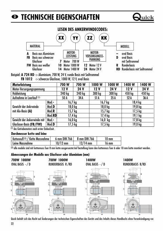
Motorleistung 700 W 700 W 1000 W 1000 W 1400 W 1400 WMotor-Versorgungsspannung 12 V 24 V 12 V 24 V 12 V 24 VHubleistung 24O kg 24O kg 300 kg 300 kg 450 kg 450 kgAufnahme in Leerlauf (1) 50 A 34 A 51 A 35 A 52 A 36 A
Mod.- 16,7 kg 16,7 kg 18,4 kgGewicht der Ankrwinde Mod.D 18,0 kg 18,0 kg 19,8 kgmit Alu-Basis (A) Mod.R 15,7 kg 15,7 kg 17,5 kg
Mod.RD 17,4 kg 17,4 kg 19,1 kgGewicht der Ankerwinde mit Mod.- 16,0 kg 16,0 kg 17,8 kgGlasfaser-Basis (FB/FW) Mod.D 17,5 kg 17,5 kg 19,0 kg
Quick behält sich das Recht auf Änderungen der technischen Eigenschaften des Geräts und des Inhalts dieses Handbuchs ohne Vorankündigung vor.
XX YY ZZ KK
MATERIAL
A Basis aus AluminiumFB Basis aus schwarzer
GlasfaserFW Basis aus weißer
Glasfaser
– oval BasisD oval Basis
mit SeiltrommelR RunderbasisRD Runderbasis mit Seiltrommel
MOTOR-VERSORGUNGSS-
PANNUNG
12 Motor 12 V24 Motor 24 V
MOTOR-LEISTUNG
7 Motor 700 W10 Motor 1000 W14 Motor 1400 W
MODELL
Kettennuß (2) / Kette Massnahme 6 mm DIN 766 8 mm DIN 766 10 mmLeine Massnahme 10/12 mm 12/14 mm 16 mm
Durchmesser kette und leine
(2) alle modele sind mit kettennuss fuer 8 mm kette ausgeruestet.Auf bestellung kann den kettennuss fuer 6 oder 10 mm kette montiert werden.
700W 1000W OVAL BASIS - / D
Abmessungen der Modelle aus Glasfaser oder Aluminium (mm)
700W 1000W RUNDERBASIS R /RD
330
min.
25
150
7887
102
250
168
98
min.
25
168
330
150
102
100
163
Ø 15
5
min.
25
168
345
177
115
100
163
Ø 15
5
1400WOVAL BASIS - / D
1400WRUNDERBASIS R/RD
min.
25
168
345
177
78
115
87
250
98
TECHNISCHE EIGENSCHAFTEN
23
VOR DEM GEBRAUCH DER ANKERWINDE DIESE BETRIEBSANLEITUNG AUFMERKSAM DURCH-LESEN. IM ZWEIFELSFALL WENDEN SIE SICH BITTE AN DEN QUICK-VERTRAGSHÄNDLER.
ACHTUNG: die Quick-Ankerwinden wurden für das Lichten des Ankers entwickelt und gebaut. Diese Vor-richtungen für keine anderen Zwecke verwenden. Quick haftet nicht für direkte oder indirekte Schä-den, die durch einen unsachgemäßen Gebrauch des Geräts entstehen.
VORGANGSWEISE FÜR DIE MONTAGEDie Ankerwinde setzt sich aus zwei separaten Teilen zusammen:
• Der obere Teil (Top) muß an Deck (Basis 4 oder 17).• Der Getriebemotor muß unter Deck montiert werden (Untersetzungsgetriebe 11, elektrischer Motor 14).
1. Die Mutter (10) von der Befestigungsschraube abschrauben, um Top und Getriebemotor zu trennen.2. Zur Positionierung der Ankerwinde die Kettennuß auf die Bugstütze ausrichten (Leine oder Kette parallel
zum Boden des Decks und um die Kettennuß mit einem Winkel von ca. 180 ° gewickelt).3. Vor Anbringung der Bohrungen folgendes kontrollieren: Unter Deck dürfen keine Hindernisse für die In-
stallation des unteren Teils vorliegen. Dicke des Decks zwischen einschließlich 25 und 50 mm. Im Falle an-derer Dicken wenden Sie sich an den Quick-Vertragshändler. Außerdem kontrollieren, ob die Deckoberflä-chen oben und unten so weit als möglich parallel sind. Anderenfalls den Unterschied entsprechend ausglei-chen (fehlende Parallelität könnte einen Abfall der Motorleistung bewirken).
4. Nach Festlegung der idealen Position, die Bohrungen anbringen. Als Bezug die mitgelieferte Dichtung (6oder 16) verwenden.
5. Das obere Teil positionieren und mit dem unteren Teil verbinden. Dazu die Welle (22 oder 23) in das Un-tersetzungsgetriebe einsetzen. Die Ankerwinde mit den mitgelieferten Schrauben an den Stiftschrauben (7)befestigen.
6. Die vom Schalter kommenden Versorgungskabel an den elektrischen Motor anschließen.
ACHTUNG: vor Durchführung des Anschlusses sicherstellen, daß an den Kabeln keine Spannung anliegt.
MONTAGE
24
ANSCHLUSSPLAN
- +
M1
M2
I TI T A LA L YY
1 2
1 2
QUICK-ZUBEHÖRTEILE FÜR DIEBETÄTIGUNG DER ANKERWINDE
FUNKFERNSTEUERUNG
Kettenzähler-Tafel
Schalter anBedientafel
UP
DOWN
BASISSYSTEMAllgemeiner Anschlußplan S. 34 Meterzähler-Fernbedienung
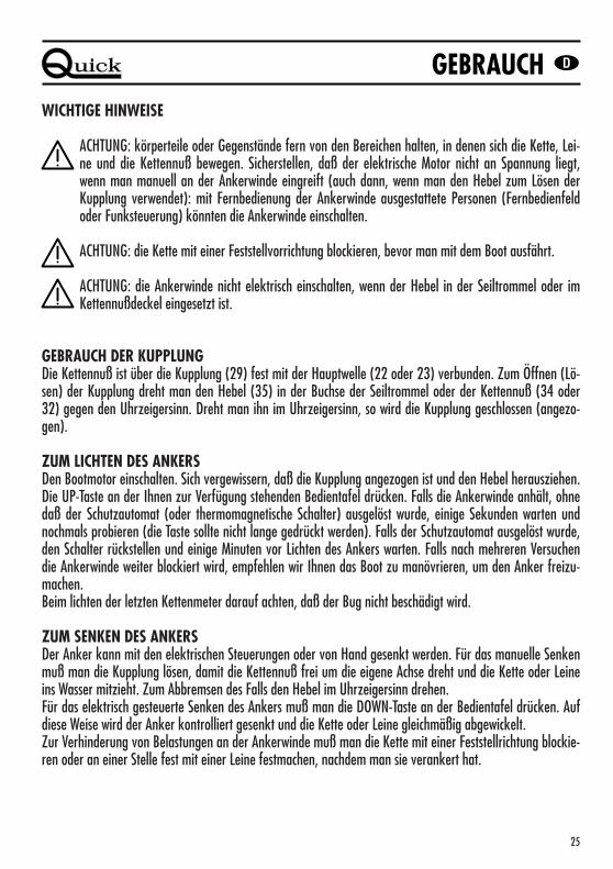
ACHTUNG: körperteile oder Gegenstände fern von den Bereichen halten, in denen sich die Kette, Lei-ne und die Kettennuß bewegen. Sicherstellen, daß der elektrische Motor nicht an Spannung liegt,wenn man manuell an der Ankerwinde eingreift (auch dann, wenn man den Hebel zum Lösen derKupplung verwendet): mit Fernbedienung der Ankerwinde ausgestattete Personen (Fernbedienfeldoder Funksteuerung) könnten die Ankerwinde einschalten.
ACHTUNG: die Kette mit einer Feststellvorrichtung blockieren, bevor man mit dem Boot ausfährt.
ACHTUNG: die Ankerwinde nicht elektrisch einschalten, wenn der Hebel in der Seiltrommel oder imKettennußdeckel eingesetzt ist.
GEBRAUCH DER KUPPLUNGDie Kettennuß ist über die Kupplung (29) fest mit der Hauptwelle (22 oder 23) verbunden. Zum Öffnen (Lö-sen) der Kupplung dreht man den Hebel (35) in der Buchse der Seiltrommel oder der Kettennuß (34 oder32) gegen den Uhrzeigersinn. Dreht man ihn im Uhrzeigersinn, so wird die Kupplung geschlossen (angezo-gen).
ZUM LICHTEN DES ANKERSDen Bootmotor einschalten. Sich vergewissern, daß die Kupplung angezogen ist und den Hebel herausziehen.Die UP-Taste an der Ihnen zur Verfügung stehenden Bedientafel drücken. Falls die Ankerwinde anhält, ohnedaß der Schutzautomat (oder thermomagnetische Schalter) ausgelöst wurde, einige Sekunden warten undnochmals probieren (die Taste sollte nicht lange gedrückt werden). Falls der Schutzautomat ausgelöst wurde,den Schalter rückstellen und einige Minuten vor Lichten des Ankers warten. Falls nach mehreren Versuchendie Ankerwinde weiter blockiert wird, empfehlen wir Ihnen das Boot zu manövrieren, um den Anker freizu-machen.Beim lichten der letzten Kettenmeter darauf achten, daß der Bug nicht beschädigt wird.
ZUM SENKEN DES ANKERSDer Anker kann mit den elektrischen Steuerungen oder von Hand gesenkt werden. Für das manuelle Senkenmuß man die Kupplung lösen, damit die Kettennuß frei um die eigene Achse dreht und die Kette oder Leineins Wasser mitzieht. Zum Abbremsen des Falls den Hebel im Uhrzeigersinn drehen.Für das elektrisch gesteuerte Senken des Ankers muß man die DOWN-Taste an der Bedientafel drücken. Aufdiese Weise wird der Anker kontrolliert gesenkt und die Kette oder Leine gleichmäßig abgewickelt.Zur Verhinderung von Belastungen an der Ankerwinde muß man die Kette mit einer Feststellrichtung blockie-ren oder an einer Stelle fest mit einer Leine festmachen, nachdem man sie verankert hat.
GEBRAUCH
26
1920
13
7
7
12
21
10
8
9
11
1
2
3
4
5
6
35
18
33
32
29
31
30
29
23
29
31
30
29
22
34
17
16
21
14
36
24
25
24
26
27
28
24
25
24
26
27
28
15
18
37
38
39
WARTUNG
POS. BEZEICHNUNG CODE
1A Inspektionstür Basis aus Aluminium S G M S G G 1 0 0 0 0 0
1B Inspektionstür Basis aus weißer Glasfaser P D G C 1 0 D W 0 0 0 0
1C Inspektionstür Basis aus schwarzer Glasfaser P D G C 1 0 D B 0 0 0 0
2A Schraub mit Basis aus Aluminium MBV0516MXSC0
2B Schraub mit base Basis aus Glasfaser MBV0530MXSC0
3A Kettenabweiser mit Basisteil M S N 1 0 V X P 0 0 0 0
3B Kettenabweiser M S N 1 0 V X D 0 0 0 0
4A Basisteil Aluminium S G M S C 1 0 V 0 0 0 0
4B Basisteil weiß Glasfaser SMPD10VW0000
4C Basisteil schwarzer Glasfaser S M P D 1 0 V B 0 0 0 0
5 Bolzen M S R 1 0 X 0 0 0 0 0 0
6 Dichtung/ovale Schablone P G B S V 1 0 0 0 0 0 0
27
ACHTUNG: sicherstellen, daß der elektrische Motornicht an Spannung liegt, wenn man manuell an derAnkerwinde eingreift. Sorgfältig die Kette oder Lei-ne vom Kettennuß oder die Leine von der Seiltrom-mel nehmen.
Die Quick-Ankerwinden werden aus seewasserfestem Ma-terial hergestellt. Dennoch muß man regelmäßig Salzabla-gerung an den Außenflächen entfernen, um Korrosion undfolglich Schäden am Gerät zu vermeiden.Sorgfältig mit Süßwasser die Oberflächen und die Teile, andenen sich Salz ablagern kann, waschen.
Einmal jährlich das Kettennuß und die Seiltrommel aus-bauen. Dabei die folgende Reihenfolge beachten:
Version mit SeiltrommelMit dem Hebel (35) die Buchse (34) lösen. Die Seiltrom-mel (33) und den oberen Kupplungskegel (29) herausneh-men. Die Befestigungsschrauben (2 oder 19) der Ketten-Abweiser (3 oder 20) lösen und entfernen. Das Kettennuß(31) ausbauen.
Version ohne SeiltrommelMit dem Hebel (35) den Kettennußdeckel (32) entriegeln.Den oberen Kupplungskegel (29) herausziehen. Die Befe-stigungsschrauben (2 oder 19) der Ketten-Abweiser (3 oder20) lösen und entfernen. Das Kettennuß (31) ausbauen.
Alle ausgebauten Teile kontrollieren, um eventuelle Korro-sion festzustellen. Das Gewinde der Welle (22 oder 23)und die Kettennuß (31) an der Stelle, an der die Kup-plungskegel aufliegen, schmieren (mit seewasserfestemSchmierfett) (29).
Regelmäßig den Bolzen (5) der Inspektionstür schmieren(nur für Ankerwinden mit Aluminiumbasis).
Eventuelle Oxydation an den Versorgungsklemmen deselektrischen Motors und an denen des Kasten mit denSchützen beseitigen. Mit Schmierfett schmieren.
ACHTUNG: der elektrische Motor der Ankerwindeist nicht dicht, er ist spritzwassergeschützt, darf je-doch nicht in Wasser getaucht werden.
WARTUNG
POS. BEZEICHNUNG CODE
7A Stiftschrauben Basis aus Aluminium M B P 0 8 0 8 0 7 X 0 0
7B Stiftschrauben Basis aus Glasfaser M B P 0 8 0 8 0 8 X 0 0
8 Paßscheib M B R 0 8 X 0 0 0 0 0 0
9 Grower M B R 0 8 X D E 0 0 0 0
10 Muttern MBD08MXEN000
11A Untersetzungsgetriebe 700-1000W M R 1 0 0 0 0 0 0 0 0 0
11B Untersetzungsgetriebe 1400W M R 1 4 0 0 0 0 0 0 0 0
12 Schraub M B D 0 6 M X E T 0 0 0
13 Paßscheib M B R 0 6 1 8 1 5 X 0 0
14A Elektromotor 700W 12V E M F 0 7 1 2 0 0 0 0 0
14B Elektromotor 700W 24V E M F 0 7 2 4 0 0 0 0 0
14C Elektromotor 1000W 12V E M F 1 0 1 2 0 0 0 0 0
14D Elektromotor 1000W 24V E M F 1 0 2 4 0 0 0 0 0
14E Elektromotor 1400W 12V Z S M 1 4 1 2 0 0 0 0 0
14F Elektromotor 1400W 24V Z S M 1 4 2 4 0 0 0 0 0
15 Keil M B H 0 5 0 5 1 5 F 0 0
16 Dichtung/runde Schablone P G B S C 1 0 0 0 0 0 0
17 Runde Basis S G M S C 1 0 C 0 0 0 0
18 Meterzählsensor S A K R E E D 0 0 0 0 0
19 Schraub MBV0520MXSC0
20 Kettenabweiser mit Runde Basis M S N 1 0 C X 0 0 0 0 0
21 Keil M B H 0 8 0 7 8 0 F 0 0
22 Kurze Welle M S A S 1 0 2 7 4 R 1 0
23 Lange Welle M S A S 1 0 3 0 8 R 0 0
24 Sprengring M B A E 2 5 2 0 Y 0 0 0
25 Lager M B J 6 0 0 5 2 R S 1 0
26 Sprengring M B A N 4 7 1 7 Y 0 0 0
27 Ölabdichtung P G P R L 2 5 4 7 7 0 0
28 Grower M B R 2 5 4 0 2 5 X 0 0
29 Kupplungskegel M S F 1 0 0 0 0 0 0 0 0
30 Magnet K P M C 0 8 0 6 0 0 0 0
31A Kettenuß 6mm Z S B 1 0 0 6 0 0 0 0 0
31B Kettenuß 8mm-5/16" Z S B 1 0 0 8 5 1 6 0 0
31C Kettenuß 10mm-3/8" Z S B 1 0 1 0 3 8 0 0 0
32 Kettennußdeckel S G M S G B 1 0 0 0 0 0
33 Seiltrommel Z S G M S E 1 0 0 0 0 0
34 Buchse S G M S D 1 0 0 0 0 0 0
35A Hebel 700-1000W M S M V T 0 4 0 0 0 0 0
35B Hebel 1400W Z S L M S H 0 0 0 0 0 0
36 Dichtung P G B M R 1 0 0 0 0 0 0
37 Schraub mit controll-hebel M S M V T 1 0 0 0 0 0 0
38A Controll-hebel schwarze P D L V T D 1 0 0 0 0 0
38B Controll-hebel weiß P D LV T D 1 0 W 0 0 0
39 Feder mit controll-hebel MMTND1000000
CÓMO SE LEE EL CÓDIGO DEL MOLINETE:
Ejemplo: A 724 RD -> aluminio, 700W, 24V, base redonda con campana / FB 1012 -> fibra negra 1000W, 12V, base oval
(1) del motorreductor después de un primer periodo de utilización
La Quick se reserva el derecho de aportar modificaciones en las características técnicas del aparato y en el contenido de este manual sin obligaciónde avisar previamente.
XX YY ZZ KK
MATERIAL
A Base de aluminioFB Base de fibra
de vidrio negroFW Base de fibra
de vidrio blanca
– Base ovalD Base oval
con campanaR Base redondaRD Base redonda con campana
TENSIÓN ALIMENTACIÓN
MOTOR12 Motor 12 V24 Motor 24 V
POTENCIAMOTOR
7 Motor 700 W10 Motor 1000 W14 Motor 1400 W
MODELO
Potencia motor 700 W 700 W 1000 W 1000 W 1400 W 1400 WTensión alimentación motor 12 V 24 V 12 V 24 V 12 V 24 VCapacidad de elevación 24O kg 24O kg 300 kg 300 kg 450 kg 450 kgAbsorción vacío (1) 50 A 34 A 51 A 35 A 52 A 36 A
Mod.- 16,7 kg 16,7 kg 18,4 kgPeso del molinete con base Mod.D 18,0 kg 18,0 kg 19,8 kgde aluminio (A) Mod.R 15,7 kg 15,7 kg 17,5 kg
Mod.RD 17,4 kg 17,4 kg 19,1 kgPeso del molinete con base Mod.- 16,0 kg 16,0 kg 17,8 kgde fibra (FB/FW) Mod.D 17,5 kg 17,5 kg 19,0 kg
Roldana (2) / Cadena soportada 6 mm DIN 766 8 mm DIN 766 10 mmCavo soportado 10/12 mm 12/14 mm 16 mm
Dimencion cadena y cavo
(2) todos los modelos son equipados con un barbotin para una cadena de 8 mm. Bajo demanda se pueden montar barbotin para cadena de 6 o de 10 mm.
700W 1000W BASE OVAL - / D
Dimensiones de los modelos de fibra o de aluminio (mm)
700W 1000W BASE REDONDA R /RD
330
min.
25
150
7887
102
250
168
98
min.
25
168
330
150
102
100
163
Ø 15
5
min.
25
168
345
177
115
100
163
Ø 15
5
1400WBASE OVAL - / D
1400WBASE REDONDA R/RD
min.
25
168
345
177
78
115
87
250
98
CARACTERÍSTICAS TÉCNICAS
29
ANTES DE UTILIZAR EL MOLINETE LEER CON ANTENCION EL PRESENTE MANUAL DE IN-STRUCCIONES. EN CASO DE DUDA CONSULTAR CON EL CONCESIONARIO VENDEDOR QUICK.
ATENCION: los molinetes Quick han sido proyectados y realizados para levar las anclas. No utilizar es-tos aparatos para otros tipos de operaciones. La Quick no asumen ningún tipo de responsabilidad pordaños directos o indirectos causados por una utilización inadecuada del aparato.
LA REFERENCIA CONTIENE: top + motorreductor - caja teleruptores - guarnición de la base - palanca - tornillos (para el ensamblaje) - manual de instrucciones - tarjeta de garantía.
HERRAMIENTAS NECESARIAS PARA LA INSTALACIONTaladro con brocas: 9 mm., 11 mm., de taza Ø 65 mm.; llaves hexagonales: 13 mm.
ACCESORIOS ACONSEJADOS POR QUICK • Mando de panel (mod. 800) • Tablero de pulsadores hermético (mod. 1002) • Mando de pie (mod. 900) • Interruptor magneto-hidráulico (mod. 10080,10100) • Cuenta-cadena para el anclaje (mod. 1102M y 1202M) • Sistema de accionamiento vía radio (mod. 1302,1352; 02, 302).
PROCEDIMIENTO DE MONTAJEEl molinete está constituido por dos partes separables:
• la parte superior (top) se debe instalar en la cubierta (base 4 ó 17)• el motorreductor se debe instalar en el interior de la embarcación (reductor 11, motor eléctrico 14).
1. Desenroscar la tuerca (10) del prisionero de fijación relativo para separar el top y el motorreductor.2. El molinete se debe colocar alineando el barbotín con la brújula de proa (cable o cadena paralelos con la
superficie de cubierta envueltos alrededor del barbotín con un ángulo de aproximadamente 180°).3. Antes de perforar los orificios comprobar lo siguiente: no deben existir obstáculos en el interior del buque
para la instalación de la parte inferior. El espesor de cubierta deberá estar comprendido entre los 25 ylos 50 mm. En caso de espesores diferentes será necesario consultar con el concesionario vendedorQuick. Verificar también que las superficies superior e inferior de la cubierta sean lo más paralelas posi-bles; si así no fuese, compensar adecuadamente la diferencia (la falta de paralelismo podría causar pér-didas de potencia del motor).
4. Una vez establecida la posición ideal, perforar los orificios utilizando la guarnición (6 ó 16) suministradacomo referencia.
5. Colocar la parte superior y unir a ésta la parte inferior, introduciendo el eje (22 ó 23) en el reductor. Fi-jar el molinete con los tornillos suministrados en los prisioneros de fijación (7).
6. Conectar los cables de alimentación provenientes del telerruptor en el motor eléctrico.
ATENCION: antes de efectuar la conexión asegurarse de que no esté presente la alimentación en loscables.
INSTALACION
30
ESQUEMA DE MONTAGE
- +
M1
M2
I TI T A LA L YY
1 2
1 2
ACCESORIOS QUICK PARA EL ACCIONAMIENTO DEL MOLINETE
RADIOMANDOS
Contametrosde panel
Mando de panel
UP
DOWN
SISTEMA BASEDiagrama de conexionesgeneral pág. 34 Tablero de pulsadores
ATENCION: no acercar partes del cuerpo u objetos a la zona donde deslizan la cadena, el cable y laroldana. Asegurarse de que no esté presente la alimentación en el motor eléctrico cuando se obramanualmente en el molinete (tampoco cuando se utilice la palanca para aflojar el embrague); de he-cho, personas equipadas con mando a distancia del molinete (tablero de pulsadores remoto o radio-mando) podrían activarlo accidentalmente.
ATENCION: bloquear la cadena con un retén antes de salir a navegar.
ATENCION: no activar eléctricamente el molinete con la palanca introducida en la campana o en la ta-pa de la roldana.
UTILIZACION DEL EMBRAGUELa roldana está unido con el eje principal (22 ó 23) mediante el embrague (29). El embrague se abre (de-senganche) utilizando la palanca (35) que, introducida en la brújula de la campana o en la tapa la roldana(34 ó 32) deberá girar hacia el sentido contrario de las manecillas del reloj. Girando hacia el sentido de lasmanecillas del reloj se provocará el cierre (enganche) del embrague.
PARA LEVAR ANCLASEncender el motor de la embarcación. Asegurarse de que el embrague esté apretado y extraer la palanca.Presionar el pulsador UP del mando a vuestra disposición. Si el molinete se para sin que el interruptor mag-neto-hidráulico (o magnetotérmico) haya saltado, esperar algunos segundos y volver a probar (evitar presio-nar continuamente el pulsador). Si el interruptor magnetotérmico ha saltado, volver a activar el interruptor yesperar algunos minutos antes de volver a levar anclas. Si después de varios intentos el molinete continúa abloquearse, aconsejamos maniobrar la embarcación para desencallar el ancla.Controlar la subida de los últimos metros de cadena para evitar que se estropee la proa.
PARA FONDEAREl tendido del ancla se puede efectuar mediante mandos eléctricos o manualmente. Para efectuar la opera-ción manualmente es necesario abrir el embrague dejando libre la roldana de manera que pueda girar sobresu propio eje y arrastrar la cadena o el cable al agua. Para frenar la caída del ancla es necesario girar la pa-lanca hacia el sentido de las manecillas del reloj.Para tender el ancla eléctricamente es necesario presionar el pulsador DOWN del mando a vuestra disposi-ción. De esta manera la bajada de la misma se podrá controlar perfectamente y el desenrollado de la cadenao del cable será regular.Para evitar solicitaciones en el molinete, una vez anclados, bloquear la cadena con un retén o fijarla en unpunto estable con un cable.
USO
32
1920
13
7
7
12
21
10
8
9
11
1
2
3
4
5
6
35
18
33
32
29
31
30
29
23
29
31
30
29
22
34
17
16
21
14
36
24
25
24
26
27
28
24
25
24
26
27
28
15
18
37
38
39
MANTENIMIENTO
POS. DENOMINACION CÓDIGO
1A Portilla de inspecciónbase de aluminio S G M S G G 1 0 0 0 0 0
1B Portilla de inspecciónbase fibra blanca P D G C 1 0 D W 0 0 0 0
1C Portilla de inspecciónbase fibra negra P D G C 1 0 D B 0 0 0 0
2A Tornillo per base de aluminio MBV0516MXSC0
2B Tornillo per base fibra MBV0530MXSC0
3A Separa-cadena per base oval M S N 1 0 V X P 0 0 0 0
3B Separa-cadena per base fibra M S N 1 0 V X D 0 0 0 0
4A Base oval aluminio S G M S C 1 0 V 0 0 0 0
4B Base oval fibra blanca SMPD10VW0000
4C Base oval fibra negra S M P D 1 0 V B 0 0 0 0
5 Pivote M S R 1 0 X 0 0 0 0 0 0
6 Guarnición/plantilla oval P G B S V 1 0 0 0 0 0 0
33
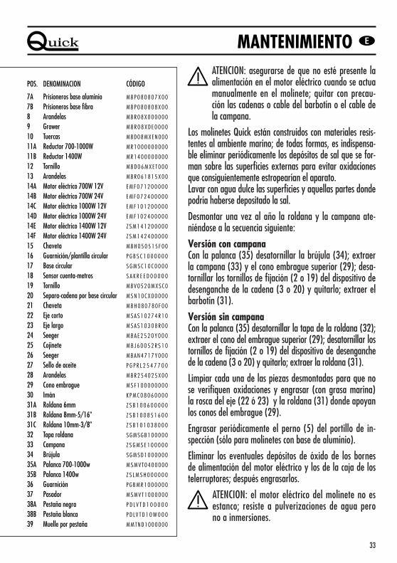
ATENCION: asegurarse de que no esté presente laalimentación en el motor eléctrico cuando se actuamanualmente en el molinete; quitar con precau-ción las cadenas o cable del barbotín o el cable dela campana.
Los molinetes Quick están construidos con materiales resis-tentes al ambiente marino; de todas formas, es indispensa-ble eliminar periódicamente los depósitos de sal que se for-man sobre las superficies externas para evitar oxidacionesque consiguientemente estropearían el aparato.Lavar con agua dulce las superficies y aquellas partes dondepodría haberse depositado la sal.
Desmontar una vez al año la roldana y la campana ate-niéndose a la secuencia siguiente:
Versión con campanaCon la palanca (35) desatornillar la brújula (34); extraerla campana (33) y el cono embrague superior (29); desa-tornillar los tornillos de fijación (2 o 19) del dispositivo dedesenganche de la cadena (3 o 20) y quitarlo; extraer elbarbotín (31).
Versión sin campanaCon la palanca (35) desatornillar la tapa de la roldana (32);extraer el cono del embrague superior (29); desatornillar lostornillos de fijación (2 o 19) del dispositivo de desenganchede la cadena (3 o 20) y quitarlo; extraer la roldana (31).
Limpiar cada una de las piezas desmontadas para que nose verifiquen oxidaciones y engrasar (con grasa marina)la rosca del eje (22 ó 23) y la roldana (31) donde apoyanlos conos del embrague (29).
Engrasar periódicamente el perno (5) del portillo de in-spección (sólo para molinetes con base de aluminio).
Eliminar los eventuales depósitos de óxido de los bornesde alimentación del motor eléctrico y los de la caja de lostelerruptores; después engrasarlos.
ATENCION: el motor eléctrico del molinete no esestanco; resiste a pulverizaciones de agua perono a inmersiones.
MANTENIMIENTO
POS. DENOMINACION CÓDIGO
7A Prisioneros base aluminio M B P 0 8 0 8 0 7 X 0 0
7B Prisioneros base fibra M B P 0 8 0 8 0 8 X 0 0
8 Arandelas M B R 0 8 X 0 0 0 0 0 0
9 Grower M B R 0 8 X D E 0 0 0 0
10 Tuercas MBD08MXEN000
11A Reductor 700-1000W M R 1 0 0 0 0 0 0 0 0 0
11B Reductor 1400W M R 1 4 0 0 0 0 0 0 0 0
12 Tornillo M B D 0 6 M X E T 0 0 0
13 Arandelas M B R 0 6 1 8 1 5 X 0 0
14A Motor eléctrico 700W 12V E M F 0 7 1 2 0 0 0 0 0
14B Motor eléctrico 700W 24V E M F 0 7 2 4 0 0 0 0 0
14C Motor eléctrico 1000W 12V E M F 1 0 1 2 0 0 0 0 0
14D Motor eléctrico 1000W 24V E M F 1 0 2 4 0 0 0 0 0
14E Motor eléctrico 1400W 12V Z S M 1 4 1 2 0 0 0 0 0
14F Motor eléctrico 1400W 24V Z S M 1 4 2 4 0 0 0 0 0
15 Chaveta M B H 0 5 0 5 1 5 F 0 0
16 Guarnición/plantilla circular P G B S C 1 0 0 0 0 0 0
17 Base circular S G M S C 1 0 C 0 0 0 0
18 Sensor cuenta-metros S A K R E E D 0 0 0 0 0
19 Tornillo MBV0520MXSC0
20 Separa-cadena por base circular M S N 1 0 C X 0 0 0 0 0