

IS 549-N REV. 180598 - 1Italiano
Avvertenze generali
Installare in posizione verticale lontano da possibiliinfiltrazioni d'acqua.
Installare lontano da eccessive fonti di calore( es. collettori di scarico ).
Installare lontano dalla bobina d'accensione epassare il cablaggio lontano dai cavi dell'altatensione.
Realizzare delle buone connessioni elettricheevitando l'uso dei " rubacorrente ".Si tenga presente che la migliore connessioneè la saldatura debitamente isolata.
Non aprire per nessun motivo la scatola delVariatore, soprattutto con il motore in moto o ilquadro inserito .L'A.E.B. declina ogni responsabilità per danni acose e persone derivati dalla manomissione delpropio dispositivo da parte di personale nonautorizzato.

IS 549-N REV. 180598 - 1Italiano
FUNZIONE EMERGENZA
Avvisare il cliente che in caso di avaria il Variatore èdotato di connettore di emergenza che lo esclude eripristina il collegamento originale.
PER ESCLUDERLO OPERARE COME SEGUE
FUNZIONAMENTO NORMALELa spina del cablaggio è inserita nelconnettore BIANCO della centralina delVariatore
FUNZIONE EMERGENZATogliere il cablaggio dal connettoreBIANCO di funzionamento normale edinserirlo nel connettore ROSSO diEMERGENZA come da schema qui afianco riportato.
Caratteristiche Tecniche
Tensione di alimentazione 10 ÷ 14 Vdc
Campo regolazione anticipo 6° ÷ 15°
Ingombri scatola Variatore altezza 102 mmprofondità 35 mmlarghezza 102 mmØ foro di fissaggio 6 mm
IS 549-N REV. 180598 - 1Italiano
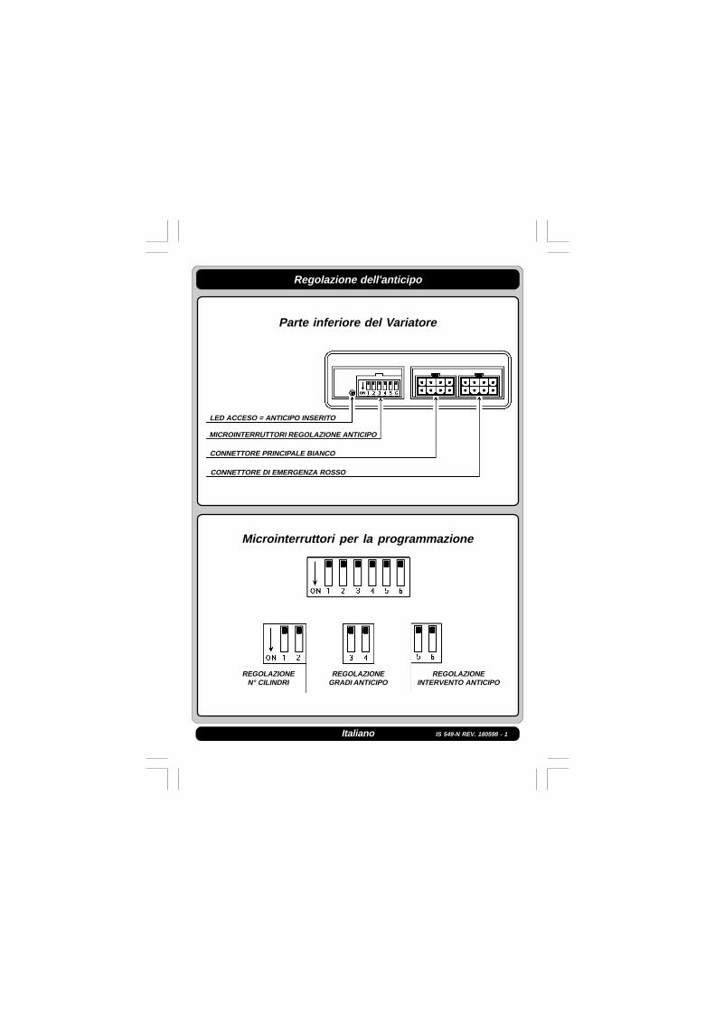
Regolazione dell'anticipo
Parte inferiore del Variatore
Microinterruttori per la programmazione
MICROINTERRUTTORI REGOLAZIONE ANTICIPO
CONNETTORE PRINCIPALE BIANCO
CONNETTORE DI EMERGENZA ROSSO
LED ACCESO = ANTICIPO INSERITO
REGOLAZIONEN° CILINDRI
REGOLAZIONEGRADI ANTICIPO
REGOLAZIONEINTERVENTO ANTICIPO

IS 549-N REV. 180598 - 1Italiano
Schema per la programmazione dei microinterruttori
PROGRAMMAZIONE NUMERO DI CILINDRI
motore 4 cilindri motore 6 cilindri
motore 5 cilindri motore 8 cilindri
PROGRAMMAZIONE GRADI DI ANTICIPO
12° di anticipo 9° di anticipo
6° di anticipo 15° di anticipo
IS 549-N REV. 180598 - 1Italiano
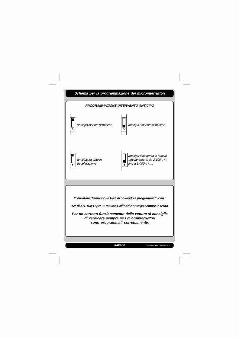
Schema per la programmazione dei microinterruttori
PROGRAMMAZIONE INTERVENTO ANTICIPO
anticipo inserito al minimo anticipo dinserito al minimo
anticipo disinserito in fase dianticipo inserito in decelerazione da 2.100 g / mdecelerazione fino a 1.000 g / m.
Il Variatore d'anticipo in fase di collaudo è programmato con :
12° di ANTICIPO per un motore 4 cilindri e anticipo sempre inserito .
Per un corretto funzionamento della vettura si consigliadi verificare sempre se i microinterruttori
sono programmati correttamente.

IS 549-N REV. 180598 - 1
Schema d'installazione per le seguenti vetture
ALFA ROMEO :33 1300 Bobina e spinterogeno33 1500 Bobina e spinterogeno33 1700 Bobina e spinterogenoBMW :316 - 318 Carburatore Bobina e spinterogeno320i L - Jetronic Bobina e spinterogenoFORD :SIERRA 1600-1800-2000i Bobina e spinterogenoSCORPIO 2000i Bobina e spinterogenoMERCEDES :190E 1800-2000 Bobina e spinterogeno200E Bobina e spinterogenoROVER :214i - 414i 16V cat. Bobina e spinterogeno820 Bobina e spinterogenoSEAT :IBIZA 1500i Bobina e spinterogenoVOLVO:240i K - Jetronic Bobina e spinterogeno740i K - Jetronic Bobina e spinterogeno
Italiano

IS 549-N REV. 180598 - 1
Schema d'installazione per le seguenti vetture
FIAT :UNO 60 Bobina e spinterogenoUNO 70 Carburatore Bobina e spinterogenoDUNA 60 Bobina e spinterogenoDUNA 70 Bobina e spinterogenoREGATA 70 Bobina e spinterogeno
Italiano

IS 549-N REV. 180598 - 1
Schema d'installazione per le seguenti vetture
RENAULT :TWINGO 1200i cat. Bobina e spinterogeno
Italiano

IS 549-N REV. 180598 - 1
Schema d'installazione per le seguenti vetture
CITROEN :BX 1400 Bobina e spinterogenoAX 1100 Bobina e spinterogenoPEUGEOT :205 1.0 - 1.1 - 1.4 Bobina e spinterogeno309 1.1 - 1.4 Bobina e spinterogeno
Italiano

IS 549-N REV. 180598 - 1
Schema d'installazione per le seguenti vetture
AUTOBIANCHI :Y10 Fire Bobina e spinterogenoFIAT :UNO 45 Fire Bobina e spinterogenoUNO 60 Bobina e spinterogenoTIPO 1100 Bobina e spinterogenoTIPO 1400 Bobina e spinterogenoTEMPRA 1400 Bobina e spinterogeno
Italiano

IS 549-N REV. 180598 - 1
Schema d'installazione per le seguenti vetture
DODGE :Dakota 3.9i cat. Bobina e spinterogeno
Italiano

IS 549-N REV. 180598 - 1English
Install in an upright position far from any possibleinfiltration of water.
Install far from any sources of excessive heat (eg. exhaustmanifold).
Install far from the ignition coil and pass the wiring far from thehigh voltage cables.
Make good electrical connections without usinga “current tap.”Bear in mind that the best connection is dulyinsulated welding.
Never open the processor box for any reason whatsoever,especially with the engine running or the panel switched on.A.E.B. disclaims all liability for any damage or injuryderiving from unauthorized personnel tampering with itsdevice.
General Warnings

IS 549-N REV. 180598 - 1English
Technical Specifications
Feeding Tension 10 ÷ 14 Vdc
Advance Regulation Field 6° ÷ 15°
Overal dimensions of the height 102 mmElectronic Advance Variator depth 35 mmBox width 102 mm
Ø fixing hole 6 mm
EMERGENCY FUNCTION
S.O.S. Warn the customer that in the event of failure, theprocessor is equipped with an emergency connector thatexcludes it and restores the original connection.
TO EXCLUDE IT PROCEED AS FOLLOWS
NORMAL OPERATIONThe wiring plug is inserted in the WHITEconnector of the processor unit.
EMERGENCY OPERATIONTake the wiring out of the WHITEconnector for normal operation andinsert it into the RED EMERGENCYconnector as shown in the diagramalongside.
IS 549-N REV. 180598 - 1English
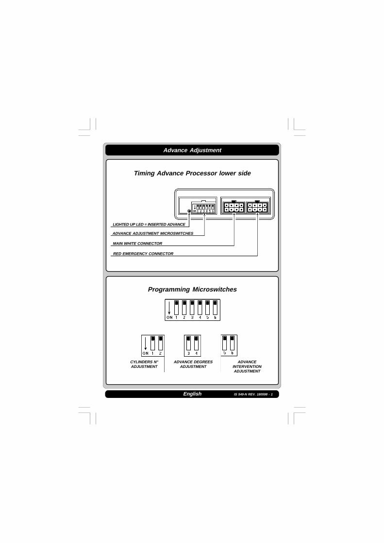
Advance Adjustment
Timing Advance Processor lower side
Programming Microswitches
ADVANCE ADJUSTMENT MICROSWITCHES
MAIN WHITE CONNECTOR
RED EMERGENCY CONNECTOR
LIGHTED UP LED = INSERTED ADVANCE
CYLINDERS N°ADJUSTMENT
ADVANCE DEGREESADJUSTMENT
ADVANCEINTERVENTIONADJUSTMENT

IS 549-N REV. 180598 - 1English
Drawing for the microswitches programming
CYLINDERS NUMBER PROGRAMMING
4 cylinders engine 6 cylinders engine
5 cylinders engine 8 cylinders engine
ADVANCE DEGREES PROGRAMMING
advance of 12° advance of 9°
advance of 6° advance of 15°

IS 549-N REV. 180598 - 1English
Drawing for the microswitches programming
ADVANCE INTERVENTION PROGRAMMING
advance always inserted advance not inserted at idle
advance not inserted duringadvance always inserted the deceleration from 2100
R.P.M. till 1000 R.P.M.
The Timing Advance Processor during the testphase is programmed with :
Advance of 12° for a 4 cylinders engine andadvance always inserted
For a right car working, it is advised to always verify if themicroswitches are correctly programmed.

IS 549-N REV. 180598 - 1
Wires and components identification codes
1 + 12V Under key
2 Rev counter
3 BROWN WIRE
4 BLACK WIRE
5 Electronic ignition
6 Ignition coil
7 RED WIRE
8 GREEN - RED WIRE
9 To the BLUE wire of the Change-over Switch
10 BLUE WIRE
11 YELLOW - GREEN WIRE
12 Ground
13 Please note. If the car has Rev counter problems, we suggest you to
disconnect the bridge between the N°3 and N°4 of the code 407 wire
connectors and get the two N°4 well connected together.
14 Fiat coil kit Code 407
English

IS 549-N REV. 180598 - 1
Instructions générales
Français
Installer en position verticale loin de toute infiltrationd’eau éventuelle.
Installer loin d’une source de chaleur trop élevée (ex:collecteur d’échappement).
Installer loin de la bobine d’allumage et passer lecâblage loin des câbles de haute tension.
Effectuer les connexions dans les règles de l’art.Il est rappelé que la meilleure connexion estla soudure adéquatement isolée.N’ouvrir sous aucun motif le boîtier du variateur,surtout avec le moteur en marche ou le tableauactivé.AEB décline toute responsabilité en cas de dégâtsà des personnes ou à des biens provoqués par lamanipulation de son dispositif par un personnelnon autorisé.

IS 549-N REV. 180598 - 1
Caractéristiques techniques
Tension d’alimentation de 10 à 14 Vdc
Champ de réglage de l’avance de 6° à 15°
Dimensions boîtier du variateur hauteur 102 mmprofondeur 35 mmlargeur 102 mmø trou de fixation 6 mm
Français
FONCTION DE SECOURS
Avertir le client qu’en cas de panne sur le variateur,celui-ci est équipé d’un connecteur de secours qui ledéconnecte et restaure la connexion d’origine.
POUR LE DECONNECTER OPERER DE LA FACON SUIVANTE
FONCTIONNEMENT NORMALLa fiche du câblage est fichée dans leconnecteur BLANC de la centraledu variateur.
FONCTION DE SECOURSEnlever le câblage du connecteurBLANC de fonctionnement normalet le brancher dans le connecteurROUGE DE SECOURS conformémentau schéma ci-contre.

IS 549-N REV. 180598 - 1Français
Réglage de l' Avance
Côté inférieure du Variateur
Microinterrupteurs pour la programmation
MICROINTERRUPTEURS RÉGLAGE AVANCE
CONNECTEUR PRINCIPAL BLANC
CONNECTEUR D'URGENCE ROUGE
VOYANT ALLUMÉ = AVANCE INSÉRÉ
RÉGLAGEN° CYLINDRES
RÉGLAGE DEGRÉSAVANCE
RÉGLAGEINTERVENTION
AVANCE
IS 549-N REV. 180598 - 1Français
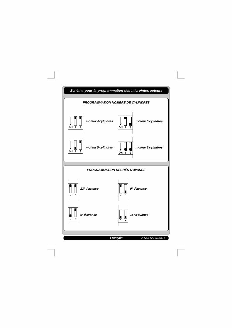
Schéma pour la programmation des microinterrupteurs
PROGRAMMATION NOMBRE DE CYLINDRES
moteur 4 cylindres moteur 6 cylindres
moteur 5 cylindres moteur 8 cylindres
PROGRAMMATION DEGRÉS D'AVANCE
12° d'avance 9° d'avance
6° d'avance 15° d'avance

IS 549-N REV. 180598 - 1Français
Schéma pour la programmation des microinterrupteurs
PROGRAMMATION INTERVENTION AVANCE
avance toujours inséré avance désinséré au ralenti
avance désinséré en phase deavance toujours inséré décélération de 2100 tours /
minute à 1000 tours / minute
Le Variateur d'avance en phase de vérification est programmé avec :
12° d'avance pour un moteur 4 cylindres etavance toujours inséré.
Pour un fonctionnement correcte de la voiture, on vousconséille de vérifier toujours si les microinterrupteurs
ont été programmé correctement.

IS 549-N REV. 180598 - 1Français
Légende des fils et des composants
1 + 12 Volts sous clé
2 Compte-tours
3 FIL MARRON
4 FIL NOIR
5 Allumage électronique
6 Bobine d' allumage
7 FIL ROUGE
8 FIL VERT - ROUGE
9 Au fil BLEU du commutateur
10 FIL BLEU
11 FIL JAUNE - VERT
12 Masse
13 NB : Si la voiture devait avoir des problèmes de compte-tours, il est
conseillé d' interrompre le pont entre les connecteurs N°3 et N°4 du
câblage code 407 et de connecter les deux N°4 ensemble
14 Kit bobine Fiat Code 407

IS 549-N REV. 180598 - 1Español
Instalar en posición vertical lejos de posibles infiltracionesde agua.
Instalar lejos de excesivas fuentes de calor ( por ej. colectoresde vaciado ).
Instalar lejos de la bobina de encendido y pasar el cableadolejos de los cables de alta tensión.
Realizar buenas conexiones eléctricas evitando el usodel “robacorriente”.Hay que tener en cuenta que la mejor conexión esla soldadura debidamente aislada.
No abrir por ningún motivo la caja del Variador, sobretodo con el motor en marcha o el cuadro conectado.A.E.B. declina toda responsabilidad por daños apersonas o cosas derivados de la manipulacióndel dispositivo por parte de personal no autorizado.
Obserrvaciones Generales

IS 549-N REV. 180598 - 1
FUNCIÓN EMERGENCIA
S.O.S Avisar al cliente que en caso de avería el Variadorconsta de un conector de emergencia que lo excluye,restableciendo la conexión original.
PARA EXCLUIRLO ACTUAR DE LA SIGUIENTE MANERA
FUNCIONAMIENTO NORMALEl enchufe de los cables está puesto enel conector BLANCO de la centralitadel Variador.
FUNCIÓN EMERGENCIAQuitar el cable del conector BLANCOde funcionamiento normal y conectarloen el conector ROJO de EMERGENCIAcomo se muestra en el esquemareproducido al lado.
Caracterìsticas Tecnicas
Tensión de alimentación 10 - 14 Vdc
Campo regulación anticipo 6° - 15°
Medidas caja Variador Altura 102 mmProfundidad 35 mmAnchura 102 mmDiám. orificio de fijación 6 mm
Español

IS 549-N REV. 180598 - 1Español
Regulación del anticipo
Lado inferior del Variador
Microinterruptores por la programación
MICROINTERRUPTORES REGULACIÓN ANTICIPO
CONECTADOR PRINCIPAL BLANCO
CONECTADOR EMERGENCIA ROJO
LED ENCENDIDO = ANTICIPO INSERTADO
REGULACIÓNN° CILINDROS
REGULACIÓNGRADOS ANTICIPO
REGULACIÓNINTERVENCIÓN ANTICIPO

IS 549-N REV. 180598 - 1Español
Esquema por la programación de los microinterruptores
PROGRAMACIÓN NÚMERO DE CILINDROS
motor 4 cilindros motor 6 cilindros
motor 5 cilindros motor 8 cilindros
PROGRAMACIÓN GRADOS DE ANTICIPO
12° de anticipo 9° de anticipo
6° de anticipo 15° de anticipo

IS 549-N REV. 180598 - 1Español
Esquema por la programación de los microinterruptores
PROGRAMACIÓN INTERVENCIÓN ANTICIPO
anticipo siempre insertado anticipo desinsertado al mínimo
anticipo desinsertado en faseanticipo siempre insertado de deceleración de 2100
vueltas / minuto hasta 1000vueltas / minuto
El Variador de Anticipo en fase de aprobación está programado con :
12° de anticipo con un motor 4 cilindros y anticipo siempre insertado.
Para un corecto funcionamiento del coche, se aconsejasiempre verificar si los microinterruptores
están programados corectamente.

IS 549-N REV. 180598 - 1Español
Códigos de identificación hilos y componentes
1 + 12V Bajo llave
2 Cuentavueltas
3 HILO MARRON
4 HILO NERGO
5 Encendido electrónico
6 Bobina de encendido
7 HILO ROJO
8 HILO VERDE - ROJO
9 Al hilo AZUL del conmutador
10 HILO AZUL
11 HILO AMARILLO-VERDE
12 Masa
13 Nota. Si el coche tuviera problemas de cuentavueltas sugerimos
interrumpir el puente entre el N.3 y el N.4 de los conectadores del
cableado COD. 407 y conectar juntos los dos N.4
14 KIT bobina Fiat Cod. 407
IS 549-N REV. 180598 - 1Deutsch
Allgemeine Hinweise
V e r t i k a l u n d f e r n v o n m ö g l i c h e nWassereinsickerungen installieren.
Fe r n vo n z u s t a r ke n H i t z e q u e l l e n ( z . B .Auspuffkrümmern)installieren.
Von der Zündspule fern installieren und dieVerkabelung fern von Hochspannungsleitungenverlegen.
Gute Stromanschlüsse fer tigen.Der besteStromanschluß ist eine zweckmäßig isolierteVerschweißung.
Das Reglergehäuse darf auf keinen Fall geöffnetwerden, vor allem bei laufendem Motor odereingeschaltetem Armaturenbrett.A.E.B. weist bei Personen- oder Sachschäden,die auf einen Mißgriff in die A.E.B.-Vorrichtungdurch unbefugtes Personal zurückzuführen sind,jegliche Haftung zurück.

IS 549-N REV. 180598 - 1
ZUM AUSSCHLIESSEN FOLGENDERMASSEN VORGEHEN
NOT FUNKTION
Der Kunde ist darauf hinzuweisen, daß der Regler für denFall eines Defekts mit einem Notverbinder bestückt ist,der ihn ausschließt und den ursprünglichen Anschlußwiederherstellt.
NORMALBETRIEBDer Stift der Verkabelung steckt imWEISSEN Verbinder des ReglerSteuergehäuses.
NOTBETRIEBDie Verkabelung vom WEISSEN Verbinderfür Normalbetrieb abtrennen und ihn gemäßnebenstehender Abbildung in den ROTENNOT-Verbinder einstecken.
Anschlußspannung 10 ÷ 14 Vdc
Verstellungseinstellbereich 6° ÷ 15°
Gehäuse-Außenmaße Höhe 102 mmTiefe 35 mmBreite 102 mmØBefestigungsloch 6 mm
Technische Eigenschaften
Deutsch

IS 549-N REV. 180598 - 1Deutsch
Einregulierung der Verstellung
Unterer Teil des Verstellungsreglers
Mikro-Programmierschalter
WEIßER HAUPTVERBINDER
ROTER NOTVERBINDER
EINSTELLUNG DERZYLINDERZAHL
EINSTELLUNG DERVERSTELLUNGSGRADE
EINSTELLUNG DERVERSTELLUNGSBEREITSCHAFT
LED AN =VERSTELLUNG EINGESCHALTET
MIKROSCHALTER DERVERSTELLUNGSREGELUNG

IS 549-N REV. 180598 - 1Deutsch
Schema zur Programmierung der Mikroschalter
PROGRAMMIERUNG DER ZYLINDERZAHL
4-Zylinder-Motor 6-Zylinder-Motor
5-Zylinder-Motor 8-Zylinder-Motor
PROGRAMMIERUNG DER VERSTELLUNGSGRADE
12°-Verstellung 9°-Verstellung
6°-Verstellung 15°-Verstellung

IS 549-N REV. 180598 - 1Deutsch
Schema zur Programmierung der Mikroschalter
PROGRAMMIERUNG DER VERSTELLUNGSBEREITSCHAFT
Verstellung stets Verstellung beieingeschaltet Leerlauf ausgeschaltet
Verstellung während derVerstellung stets Abdrosselung von 2.100 Upmeingeschaltet bis 1.000 Upm ausgeschaltet
Der Verstellungsregler wird bei der Prüfungfolgendermaßen programmiert:
12°-Verstellung für 4-Zylinder-Motor und Verstellung stets eingeschaltet.
Für einen ordnungsgerechten Pkw-Betrieb wirdempfohlen, stets die korrekte Programmierung der
Mikroschalter zu überprüfen.

IS 549-N REV. 180598 - 1Deutsch
Identifizierungscodes für Leiter und Bestandteile
1 +12 V unter Verschluß
2 Drehzahlmesser
3 BRAUNER LEITER
4 SCHWARZER LEITER
5 Elektronische Zündung
6 Zündspule
7 ROTER LEITER
8 GRÜNER - ROTER LEITER
9 An den BLAUEN Leiter des Umschalters
10 BLAUER LEITER
11 GELB-GRÜNER LEITER
12 Erde
13 NB: Sollten auf dem PKW Drehzahlmesserprobleme bestehen,
dann raten wir dazu, die Brücke zwischen den Verbindern Nr. 3 und
Nr.4 derVerkabelung Art. 407 zu unterbrechen und die beiden mit
der Nr. 4 miteinander zu verbinden.
14 SATZ Fiat-Spulen Art. 407


