1911/31 ISTITUTO NAZIONALE DI FISICA NUCLEARE CONSIGLIO DIRETTIVO DELIBERAZIONE N. 13434 Il Consiglio Direttivo dell’Istituto Nazionale di Fisica Nucleare, riunito a Roma in data 28 novembre 2014, alla presenza di n. 33 suoi componenti su n. 34: - premesso che con deliberazione n. 12664 del 29 gennaio 2013 il Consiglio Direttivo dell’Istituto ha approvato il Memorandum of Understanding tra l’INFN ed il Laboratorio iThemba Labs della National Research Foundation (NRF) sudafricana per una collaborazione nel campo della fisica applicata e fondamentale con particolare focus sugli acceleratori di ioni e sull’utilizzo di ciclotroni di alta potenza; - tenuto conto che, nell’ambito del suddetto MoU, i Laboratori Nazionali di Legnaro (LNL) e iThemba Labs intendono rafforzare la collaborazione esistente ed avviare uno studio congiunto per il progetto relativo alla costruzione e validazione sperimentale di un front end SPES/iThemba; - visto lo schema di “Implementation Agreement between NRF and INFN on SPES – Construction of the SPES/iThemba Labs Front End”, allegato alla presente deliberazione e di essa parte integrante; - considerato che l’approvazione del documento comporta una entrata finanziaria per l’Istituto per un importo di Euro 356.000,00 come contributo ai costi di sviluppo e costruzione del front end che sarà accertata con deliberazione di variazione di Bilancio; - vista la nota del Direttore dei Laboratori Nazionali di Legnaro, Prof. Giovanni Fiorentini, del 27 ottobre 2014; - su proposta della Giunta Esecutiva; - con n. 33 voti favorevoli; DELIBERA 1) E’ approvato lo schema di “Implementation Agreement between NRF and INFN on SPES – Construction of the SPES/iThemba Labs Front End”, allegato alla presente deliberazione e di essa parte integrante. Il Presidente è autorizzato a sottoscriverlo. 2) L’accertamento della relativa entrata finanziaria, come identificato in narrativa, sarà effettuato con delibera di variazione di Bilancio.
Transcript
19-‐11/31
ISTITUTO NAZIONALE DI FISICA NUCLEARE
CONSIGLIO DIRETTIVO
DELIBERAZIONE N. 13434
Il Consiglio Direttivo dell’Istituto Nazionale di Fisica Nucleare, riunito a Roma in data 28 novembre 2014, alla presenza di n. 33 suoi componenti su n. 34:
- premesso che con deliberazione n. 12664 del 29 gennaio 2013 il Consiglio Direttivo
dell’Istituto ha approvato il Memorandum of Understanding tra l’INFN ed il Laboratorio iThemba Labs della National Research Foundation (NRF) sudafricana per una collaborazione nel campo della fisica applicata e fondamentale con particolare focus sugli acceleratori di ioni e sull’utilizzo di ciclotroni di alta potenza;
- tenuto conto che, nell’ambito del suddetto MoU, i Laboratori Nazionali di Legnaro (LNL)
e iThemba Labs intendono rafforzare la collaborazione esistente ed avviare uno studio congiunto per il progetto relativo alla costruzione e validazione sperimentale di un front end SPES/iThemba;
- visto lo schema di “Implementation Agreement between NRF and INFN on SPES –
Construction of the SPES/iThemba Labs Front End”, allegato alla presente deliberazione e di essa parte integrante;
- considerato che l’approvazione del documento comporta una entrata finanziaria per
l’Istituto per un importo di Euro 356.000,00 come contributo ai costi di sviluppo e costruzione del front end che sarà accertata con deliberazione di variazione di Bilancio;
- vista la nota del Direttore dei Laboratori Nazionali di Legnaro, Prof. Giovanni Fiorentini,
del 27 ottobre 2014;
- su proposta della Giunta Esecutiva;
- con n. 33 voti favorevoli;
DELIBERA
1) E’ approvato lo schema di “Implementation Agreement between NRF and INFN on SPES – Construction of the SPES/iThemba Labs Front End”, allegato alla presente deliberazione e di essa parte integrante. Il Presidente è autorizzato a sottoscriverlo.
2) L’accertamento della relativa entrata finanziaria, come identificato in narrativa, sarà effettuato con delibera di variazione di Bilancio.
Implementation Agreement between NRF and INFN on SPES “Construction of the SPES/iThemba LABS front end”
THE ISTITUTO NAZIONALE DI FISICA NUCLEARE having its registered office in Frascati (RM), via Enrico Fermi, n. 40 duly
represented by its President, Prof. Fernando Ferroni, CF 8400 185 05 89
(hereinafter referred to as the “INFN”)
Party of the first part,
And
The NATIONAL RESEARCH FOUNDATION (NRF)
A legal entity established in terms of the National Research Foundation Act,
No. 23 of 1998 as amended, acting through its National Facility known as
iThemba Laboratory for Accelerator Based Science, South Africa with a
registered postal address of iThemba LABS, P O Box 722, Somerset West
7129, SA and a physical address of iThemba LABS, Old Faure Road, Faure,
7131, SA duly represented by Dr Jacobus Johannes Lawrie in his capacity as
Acting Director of iThemba LABS
(hereinafter referred to as “iThemba LABS”)
Party of the second part,
jointly referred to as the PARTIES
Whereas
The INFN possesses skills in the field of ISOL target-ion source systems.
iThemba LABS wishes to equip a target station with a high power ion-source
system (ISOL front end) designed and constructed by INFN as test bench for
further development at iThemba LABS.
NRF and INFN signed on January 29th 2013 a Memorandum of
Understanding concerning
SCIENTIFIC AND TECHNICAL COLLABORATION FOR THE
DEVELOPMENT OF INNOVATIVE TARGET/ION-SOURCE ASSEMBLIES
AND BEAM DIAGNOSTICS DEVICES FOR EXISTING AND NEXT-
GENERATION RADIOACTIVE ION BEAM FACILITIES
The INFN hereby agrees to provide the ISOL front end to iThemba LABS,
under the terms and conditions set forth herein.
The following has been agreed upon: Article 1 – Purpose of the Agreement The iThemba LABS and the INFN hereby agree to conduct a joint study,
hereinafter referred to as the Study, entitled:
“Construction and experimental validation of the SPES/iThemba LABS front end project”
A detailed schedule of the Study is provided in Appendix 2 and Appendix 4
attached hereto.
The INFN shall use its best endeavor to fulfil its obligations.
Article 2 – Starting date and duration
The project will start on the day of signature by the last Party of the present
Implementation Agreement for a duration of 24 (twenty-four) months.
If the delivery of the equipment, ISOL front end, occurs before the termination
date of the Agreement, the project and the obligations of the Parties will
terminate at the date at which the ISOL front end, after the successful
scheduled tests to be performed at INFN-LNL (see Appendix 4 - Scientific and
Technical Annex), is safely delivered to iThemba LABS (within the schedule
mentioned in the attachment).
Article 3 – Principle Investigators Mr. Alberto Andrighetto (INFN)
Code doc. DOC_0000027 SPES/iThemba LABS target Front end
Rev. 00
Pag. 16 di 35
Document Content
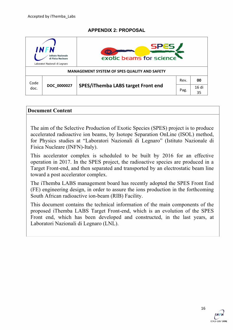
The aim of the Selective Production of Exotic Species (SPES) project is to produce accelerated radioactive ion beams, by Isotope Separation OnLine (ISOL) method, for Physics studies at “Laboratori Nazionali di Legnaro” (Istituto Nazionale di Fisica Nucleare (INFN)-Italy). This accelerator complex is scheduled to be built by 2016 for an effective operation in 2017. In the SPES project, the radioactive species are produced in a Target Front-end, and then separated and transported by an electrostatic beam line toward a post accelerator complex. The iThemba LABS management board has recently adopted the SPES Front End (FE) engineering design, in order to assure the ions production in the forthcoming South African radioactive ion-beam (RIB) Facility. This document contains the technical information of the main components of the proposed iThemba LABS Target Front-end, which is an evolution of the SPES Front end, which has been developed and constructed, in the last years, at Laboratori Nazionali di Legnaro (LNL).
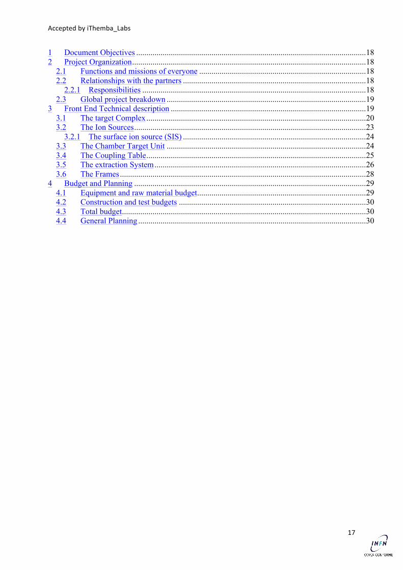
2.1 Functions and missions of everyone .................................................................................. 18 2.2 Relationships with the partners .......................................................................................... 18
2.2.1 Responsibilities .............................................................................................................. 18 2.3 Global project breakdown .................................................................................................. 19
3 Front End Technical description ................................................................................................ 19 3.1 The target Complex ............................................................................................................ 20 3.2 The Ion Sources .................................................................................................................. 23
3.2.1 The surface ion source (SIS) .......................................................................................... 24 3.3 The Chamber Target Unit .................................................................................................. 24 3.4 The Coupling Table ............................................................................................................ 25 3.5 The extraction System ........................................................................................................ 26 3.6 The Frames ......................................................................................................................... 28
4 Budget and Planning .................................................................................................................. 29 4.1 Equipment and raw material budget ................................................................................... 29 4.2 Construction and test budgets ............................................................................................ 30 4.3 Total budget ........................................................................................................................ 30 4.4 General Planning ................................................................................................................ 30
Accepted by iThemba_Labs
18
DOCUMENT OBJECTIVES The objective of this document is to present the development plan, regarding the construction and the validation tests, of an Isotope Separation OnLine (ISOL) Target Front End to be realized in Italy following the Selective Production of Exotic Species (SPES) design. The system will be shipped to South Africa and will be part of the iThemba LABS test stand. The document will present the information necessary for the evaluation of the construction feasibility, in particular: • the project organization • the technical description of the Front End, • the resources necessary for the construction.
PROJECT ORGANIZATION
FUNCTIONS AND MISSIONS OF EVERYONE The iThemba LABS project, in a first stage, asks SPES to perform the final design, the construction and the validation tests of a target Front End device. iThemba LABS will fund this project. The iThemba LABS front-end is based on the one developed at Laboratori Nazionali di Legnaro (LNL) for the Selective Production of Exotic Species (SPES) project. SPES has the technical responsibility of the design and construction. SPES will drive the validation tests on its test stand, the necessary minor mechanical adaptations of the iThemba LABS Front End will be funded by SPES. iThemba LABS representatives will be allowed to follow the construction and commissioning at Laboratori Nazionali di Legnaro (LNL), with the aim of becoming acquainted with the details of the apparatus and its operation, but the responsibilities of the technical choices remain those of the SPES group. RELATIONSHIPS WITH THE PARTNERS
In the frame of the MoU between Istituto Nazionale di Fisica Nucleare (INFN) and National Research Foundation (NRF) signed on 6-March-2013 by Istituto Nazionale di Fisica Nucleare (INFN) President (Fernando Ferroni) and National Research Foundation (NRF) iThemba LABS Director (Z.Z. Vilakazi), SPES project and iThemba LABS are collaborating for the development of innovative target/ion-source assemblies for next generation radioactive ion beam facilities.
The Technical Addendum attached to the MoU describes the detailed projects of common interest, among them “Project 1” is related to Research and development on Isotope Separation OnLine (ISOL) target defining the frame for the present project.
6.1 Responsibilities On the Istituto Nazionale di Fisica Nucleare (INFN)-Laboratori Nazionali di Legnaro
(LNL) side, the person in charge for the correct execution of the agreement is Dr. Gianfranco Prete (SPES Project Leader), on behalf of the Laboratori Nazionali di Legnaro (LNL)
Accepted by iThemba_Labs
19
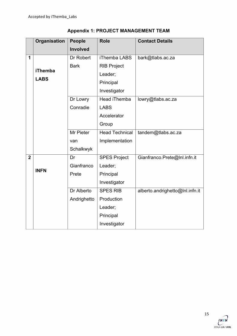
Director, and the person in charge for the technical implementation of Project 1 is Dr. Alberto Andrighetto (SPES radioactive ion-beam (RIB) production Leader). On the iThemba LABS side the contract will be under the responsibility the Leader of the Radioactive Beam Project, Dr Robert Bark. The person in charge for the technical implementation of Project 1 is the Head of the Accelerator and Engineering Department, Dr. Lowry Conradie.
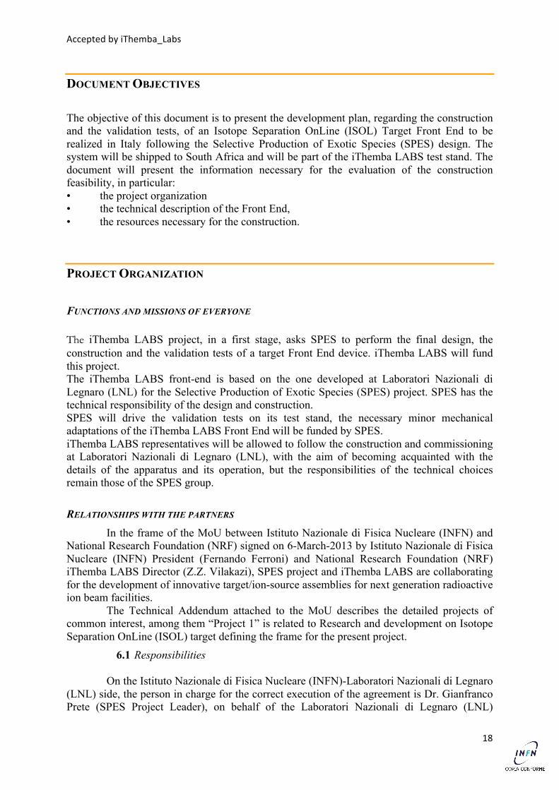
GLOBAL PROJECT BREAKDOWN
The project work breakdown structure is reported in Figure 1.
Fig. 1: The Project Work Breakdown Structure
FRONT END TECHNICAL DESCRIPTION
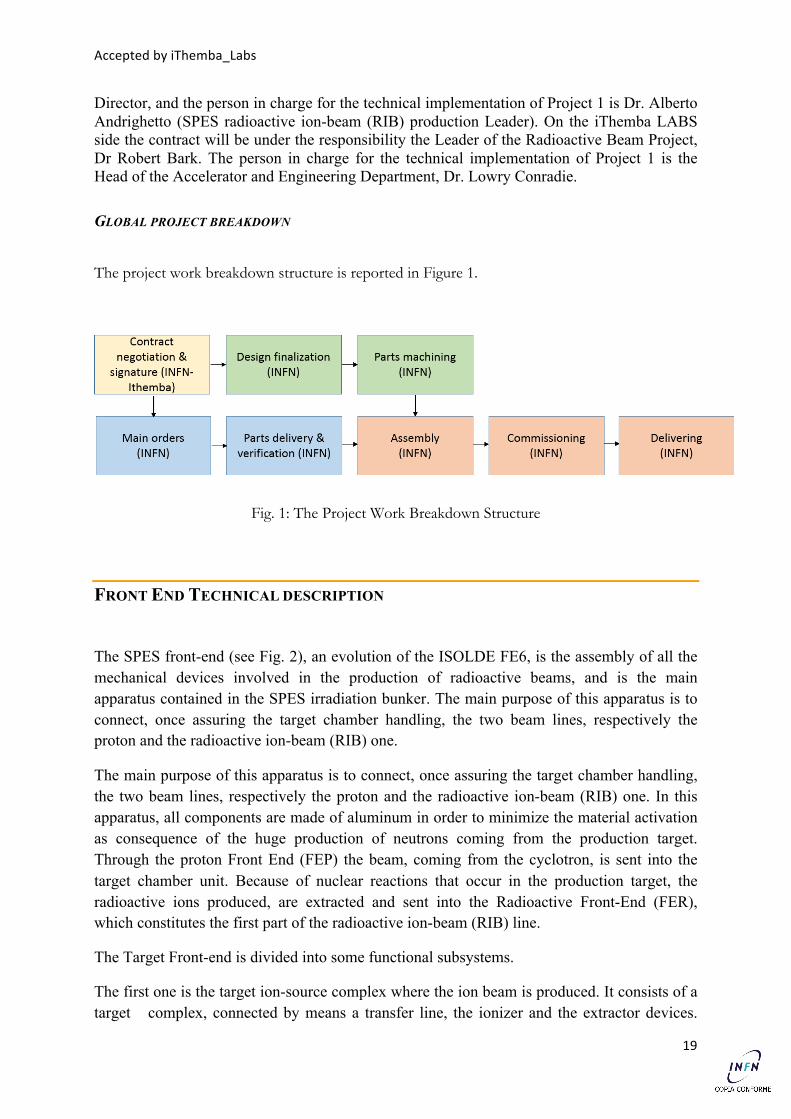
The SPES front-end (see Fig. 2), an evolution of the ISOLDE FE6, is the assembly of all the mechanical devices involved in the production of radioactive beams, and is the main apparatus contained in the SPES irradiation bunker. The main purpose of this apparatus is to connect, once assuring the target chamber handling, the two beam lines, respectively the proton and the radioactive ion-beam (RIB) one.
The main purpose of this apparatus is to connect, once assuring the target chamber handling, the two beam lines, respectively the proton and the radioactive ion-beam (RIB) one. In this apparatus, all components are made of aluminum in order to minimize the material activation as consequence of the huge production of neutrons coming from the production target. Through the proton Front End (FEP) the beam, coming from the cyclotron, is sent into the target chamber unit. Because of nuclear reactions that occur in the production target, the radioactive ions produced, are extracted and sent into the Radioactive Front-End (FER), which constitutes the first part of the radioactive ion-beam (RIB) line.
The Target Front-end is divided into some functional subsystems.
The first one is the target ion-source complex where the ion beam is produced. It consists of a target complex, connected by means a transfer line, the ionizer and the extractor devices.
Accepted by iThemba_Labs
20
The target unit is made of a graphite box containing the target disks, windows and dumps (both in graphite) disks, and is contained in a tantalum cylinder, which is resistively heated by passing a high current through it in addition to the heat supplied by the irradiating beam. A small tantalum tube, called transfer tube, connects the target unit to the ion source in order to plug in several kinds of ion sources.
The second subsystem is the Target Chamber, which contain the target and ion complex. The aluminium chamber must be easily removed, for servicing or storage, from both beam lines after the irradiation process. For this reason, the mechanical design of the target chamber strongly takes into account this effect. The target chamber unit is coupled to the proton driver and to the radioactive ion-beam (RIB)’s beam by means of quick connectors.
The third one is the extraction system, which it consists on a movable puller and an electrostatic steerer device.
The last subsystem is the frame (with a fixed and removable part). All components are made of aluminium in order to minimize the material activation as consequence of the huge production of neutrons coming from the production target.
Fig. 2: The SPES/iThemba LABS front end
The TARGET COMPLEX
The target has been designed in order to satisfy some main requirements, such as:
• High number of reactions,
• maximize the isotope release
Accepted by iThemba_Labs
21
• Low power deposition in the materials (both window and target).
A direct target configuration is chosen for the SPES project, consisting of a proton beam (E= 40 MeV) directly impinging on the target. The main problem of this configuration concerns the high power deposition of the incident beam in the production target, mainly due to the electromagnetic interactions.
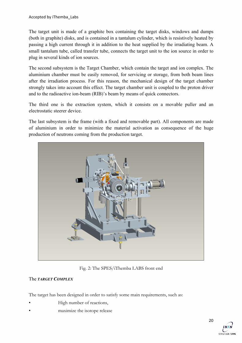
In order to solve this problem, only the protons with higher fission cross-section are exploited in a thin target, while the outgoing lower energy beam is driven towards a passive dump. In order to optimize the heat dissipation, a good solution is the use of a target constituted by multiple discs. In this way, the cooling of the target is strongly simplified: in fact, due to the void environment, the heat dissipation is fully entrusted to the thermal radiation and this mechanism is directly proportional to the body surface. The use of several thin discs of equal mass increases the total surface and allows for a better cooling.
Fig. 3: The target complex
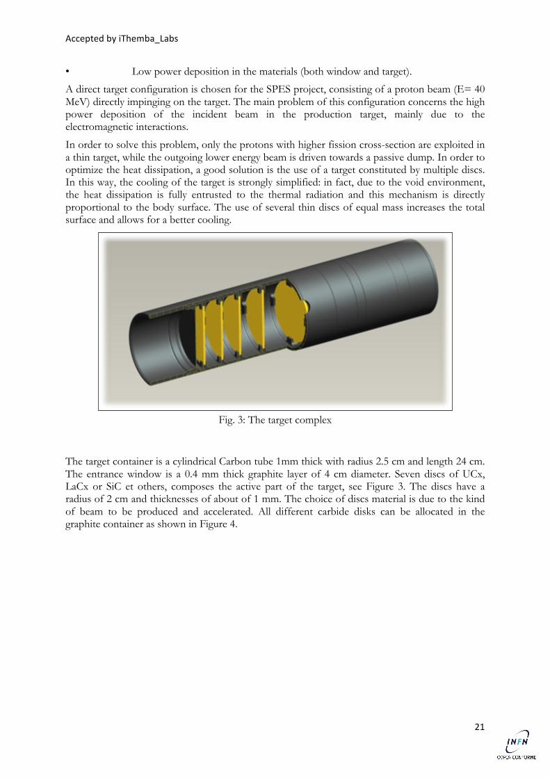
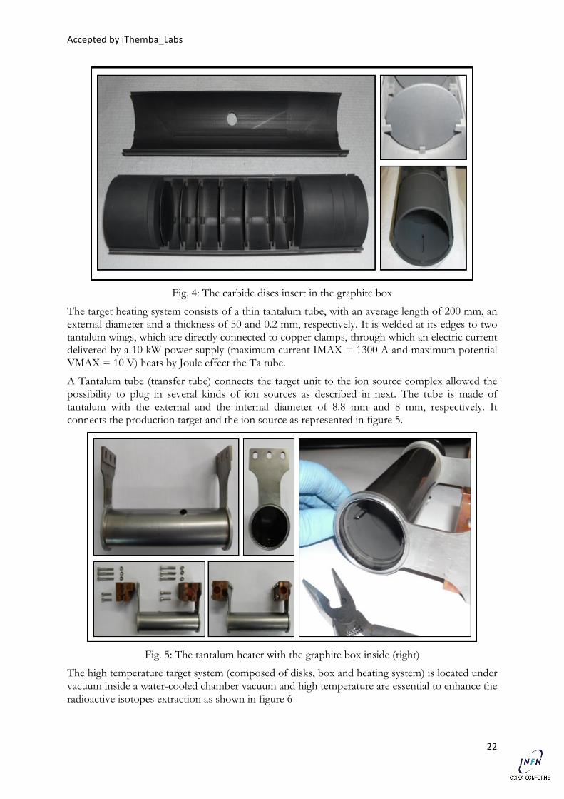
The target container is a cylindrical Carbon tube 1mm thick with radius 2.5 cm and length 24 cm. The entrance window is a 0.4 mm thick graphite layer of 4 cm diameter. Seven discs of UCx, LaCx or SiC et others, composes the active part of the target, see Figure 3. The discs have a radius of 2 cm and thicknesses of about of 1 mm. The choice of discs material is due to the kind of beam to be produced and accelerated. All different carbide disks can be allocated in the graphite container as shown in Figure 4.
Accepted by iThemba_Labs
22
Fig. 4: The carbide discs insert in the graphite box
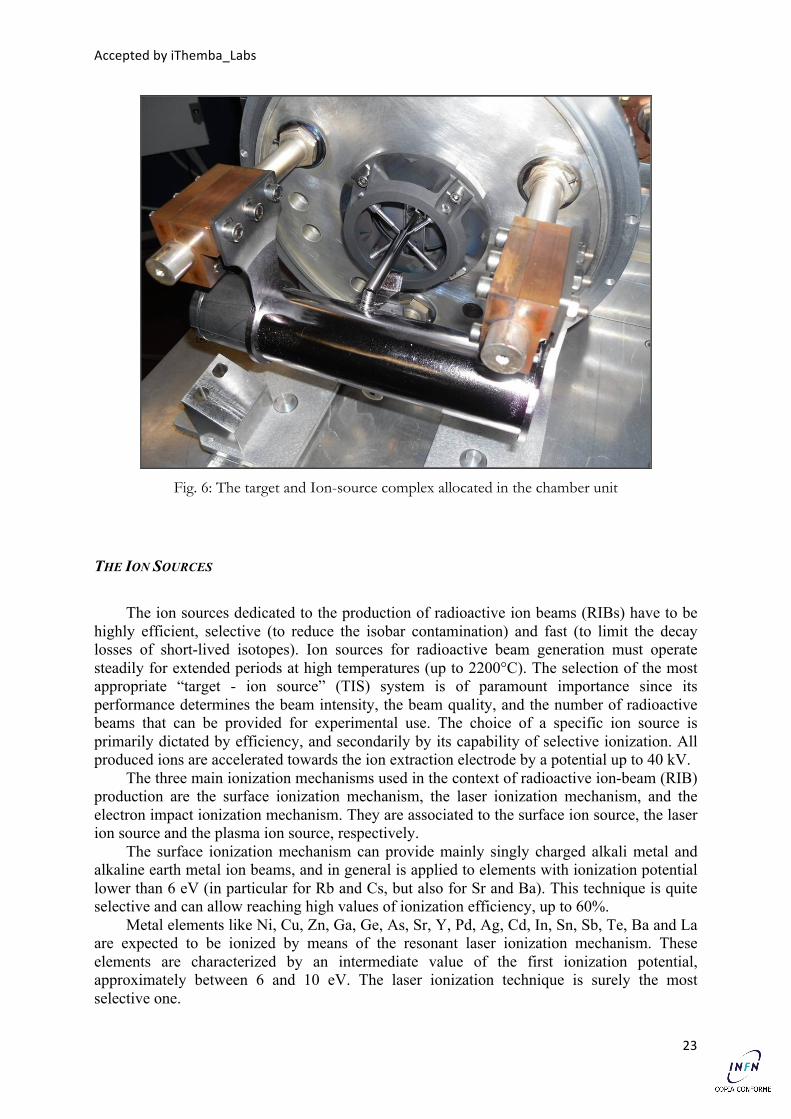
The target heating system consists of a thin tantalum tube, with an average length of 200 mm, an external diameter and a thickness of 50 and 0.2 mm, respectively. It is welded at its edges to two tantalum wings, which are directly connected to copper clamps, through which an electric current delivered by a 10 kW power supply (maximum current IMAX = 1300 A and maximum potential VMAX = 10 V) heats by Joule effect the Ta tube.
A Tantalum tube (transfer tube) connects the target unit to the ion source complex allowed the possibility to plug in several kinds of ion sources as described in next. The tube is made of tantalum with the external and the internal diameter of 8.8 mm and 8 mm, respectively. It connects the production target and the ion source as represented in figure 5.
Fig. 5: The tantalum heater with the graphite box inside (right)
The high temperature target system (composed of disks, box and heating system) is located under vacuum inside a water-cooled chamber vacuum and high temperature are essential to enhance the radioactive isotopes extraction as shown in figure 6
Accepted by iThemba_Labs
23
Fig. 6: The target and Ion-source complex allocated in the chamber unit
THE ION SOURCES
The ion sources dedicated to the production of radioactive ion beams (RIBs) have to be highly efficient, selective (to reduce the isobar contamination) and fast (to limit the decay losses of short-lived isotopes). Ion sources for radioactive beam generation must operate steadily for extended periods at high temperatures (up to 2200°C). The selection of the most appropriate “target - ion source” (TIS) system is of paramount importance since its performance determines the beam intensity, the beam quality, and the number of radioactive beams that can be provided for experimental use. The choice of a specific ion source is primarily dictated by efficiency, and secondarily by its capability of selective ionization. All produced ions are accelerated towards the ion extraction electrode by a potential up to 40 kV.
The three main ionization mechanisms used in the context of radioactive ion-beam (RIB) production are the surface ionization mechanism, the laser ionization mechanism, and the electron impact ionization mechanism. They are associated to the surface ion source, the laser ion source and the plasma ion source, respectively.
The surface ionization mechanism can provide mainly singly charged alkali metal and alkaline earth metal ion beams, and in general is applied to elements with ionization potential lower than 6 eV (in particular for Rb and Cs, but also for Sr and Ba). This technique is quite selective and can allow reaching high values of ionization efficiency, up to 60%.
Metal elements like Ni, Cu, Zn, Ga, Ge, As, Sr, Y, Pd, Ag, Cd, In, Sn, Sb, Te, Ba and La are expected to be ionized by means of the resonant laser ionization mechanism. These elements are characterized by an intermediate value of the first ionization potential, approximately between 6 and 10 eV. The laser ionization technique is surely the most selective one.
Accepted by iThemba_Labs
24
The electron impact ionization mechanism is indicated for the noble gases (Kr and Xe), the halogens (Br and I), and for Se. All these elements are characterized by an ionization potential higher than 10 eV. This ionization technique is not selective, but can reach quite high ionization efficiency values (up to 40% in the case of Xe).
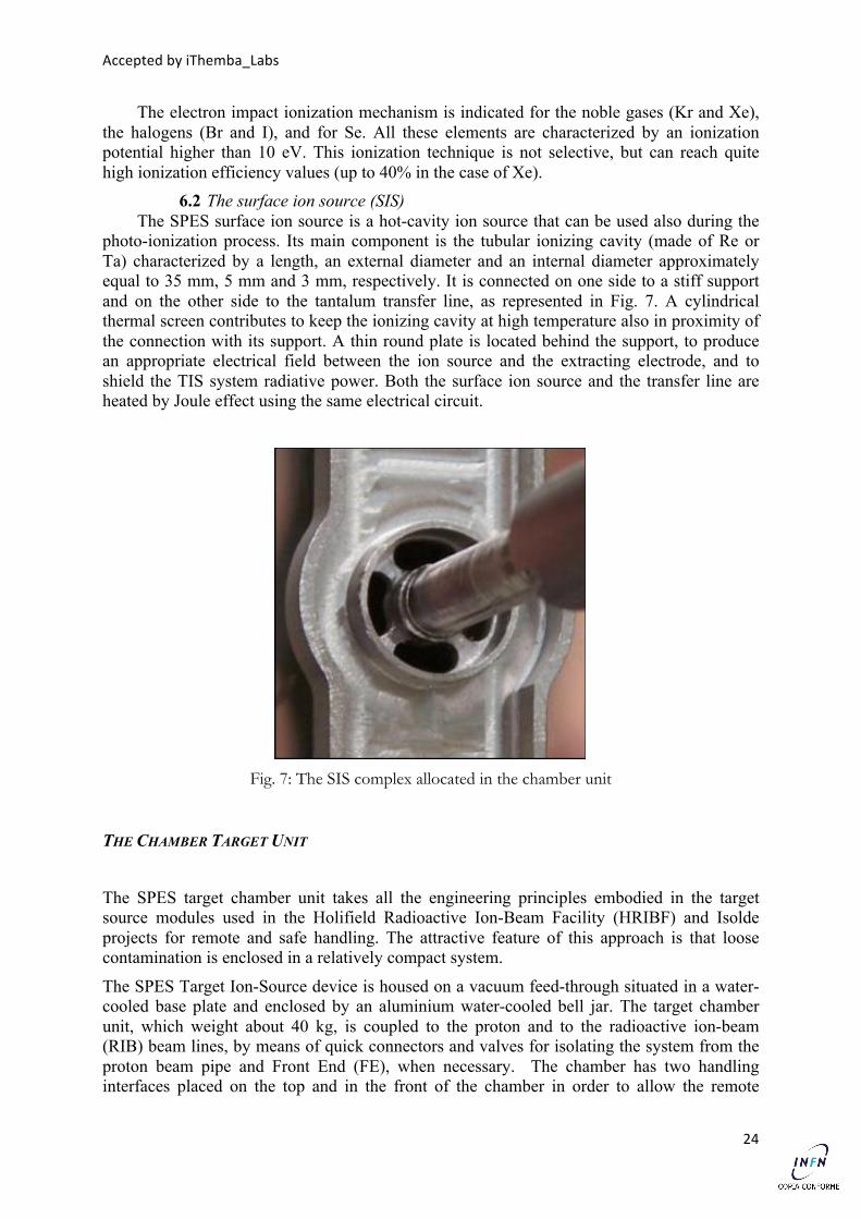
6.2 The surface ion source (SIS) The SPES surface ion source is a hot-cavity ion source that can be used also during the
photo-ionization process. Its main component is the tubular ionizing cavity (made of Re or Ta) characterized by a length, an external diameter and an internal diameter approximately equal to 35 mm, 5 mm and 3 mm, respectively. It is connected on one side to a stiff support and on the other side to the tantalum transfer line, as represented in Fig. 7. A cylindrical thermal screen contributes to keep the ionizing cavity at high temperature also in proximity of the connection with its support. A thin round plate is located behind the support, to produce an appropriate electrical field between the ion source and the extracting electrode, and to shield the TIS system radiative power. Both the surface ion source and the transfer line are heated by Joule effect using the same electrical circuit.
Fig. 7: The SIS complex allocated in the chamber unit
THE CHAMBER TARGET UNIT
The SPES target chamber unit takes all the engineering principles embodied in the target source modules used in the Holifield Radioactive Ion-Beam Facility (HRIBF) and Isolde projects for remote and safe handling. The attractive feature of this approach is that loose contamination is enclosed in a relatively compact system.
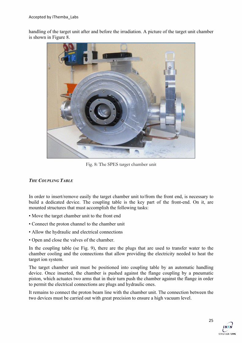
The SPES Target Ion-Source device is housed on a vacuum feed-through situated in a water-cooled base plate and enclosed by an aluminium water-cooled bell jar. The target chamber unit, which weight about 40 kg, is coupled to the proton and to the radioactive ion-beam (RIB) beam lines, by means of quick connectors and valves for isolating the system from the proton beam pipe and Front End (FE), when necessary. The chamber has two handling interfaces placed on the top and in the front of the chamber in order to allow the remote
Accepted by iThemba_Labs
25
handling of the target unit after and before the irradiation. A picture of the target unit chamber is shown in Figure 8.
Fig. 8: The SPES target chamber unit
THE COUPLING TABLE
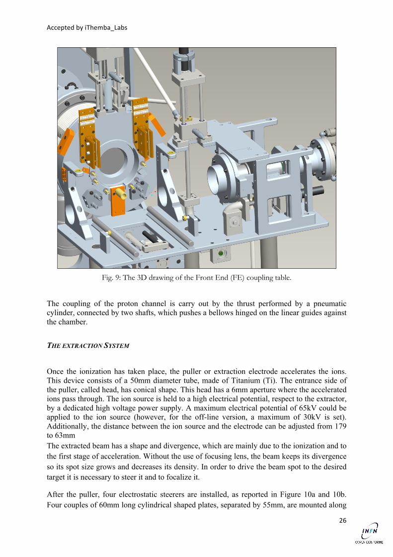
In order to insert/remove easily the target chamber unit to/from the front end, is necessary to build a dedicated device. The coupling table is the key part of the front-end. On it, are mounted structures that must accomplish the following tasks:
• Move the target chamber unit to the front end
• Connect the proton channel to the chamber unit • Allow the hydraulic and electrical connections • Open and close the valves of the chamber.
In the coupling table (se Fig. 9), there are the plugs that are used to transfer water to the chamber cooling and the connections that allow providing the electricity needed to heat the target ion system. The target chamber unit must be positioned into coupling table by an automatic handling device. Once inserted, the chamber is pushed against the flange coupling by a pneumatic piston, which actuates two arms that in their turn push the chamber against the flange in order to permit the electrical connections are plugs and hydraulic ones. It remains to connect the proton beam line with the chamber unit. The connection between the two devices must be carried out with great precision to ensure a high vacuum level.
Accepted by iThemba_Labs
26
Fig. 9: The 3D drawing of the Front End (FE) coupling table.
The coupling of the proton channel is carry out by the thrust performed by a pneumatic cylinder, connected by two shafts, which pushes a bellows hinged on the linear guides against the chamber.
THE EXTRACTION SYSTEM
Once the ionization has taken place, the puller or extraction electrode accelerates the ions. This device consists of a 50mm diameter tube, made of Titanium (Ti). The entrance side of the puller, called head, has conical shape. This head has a 6mm aperture where the accelerated ions pass through. The ion source is held to a high electrical potential, respect to the extractor, by a dedicated high voltage power supply. A maximum electrical potential of 65kV could be applied to the ion source (however, for the off-line version, a maximum of 30kV is set). Additionally, the distance between the ion source and the electrode can be adjusted from 179 to 63mm The extracted beam has a shape and divergence, which are mainly due to the ionization and to the first stage of acceleration. Without the use of focusing lens, the beam keeps its divergence so its spot size grows and decreases its density. In order to drive the beam spot to the desired target it is necessary to steer it and to focalize it.
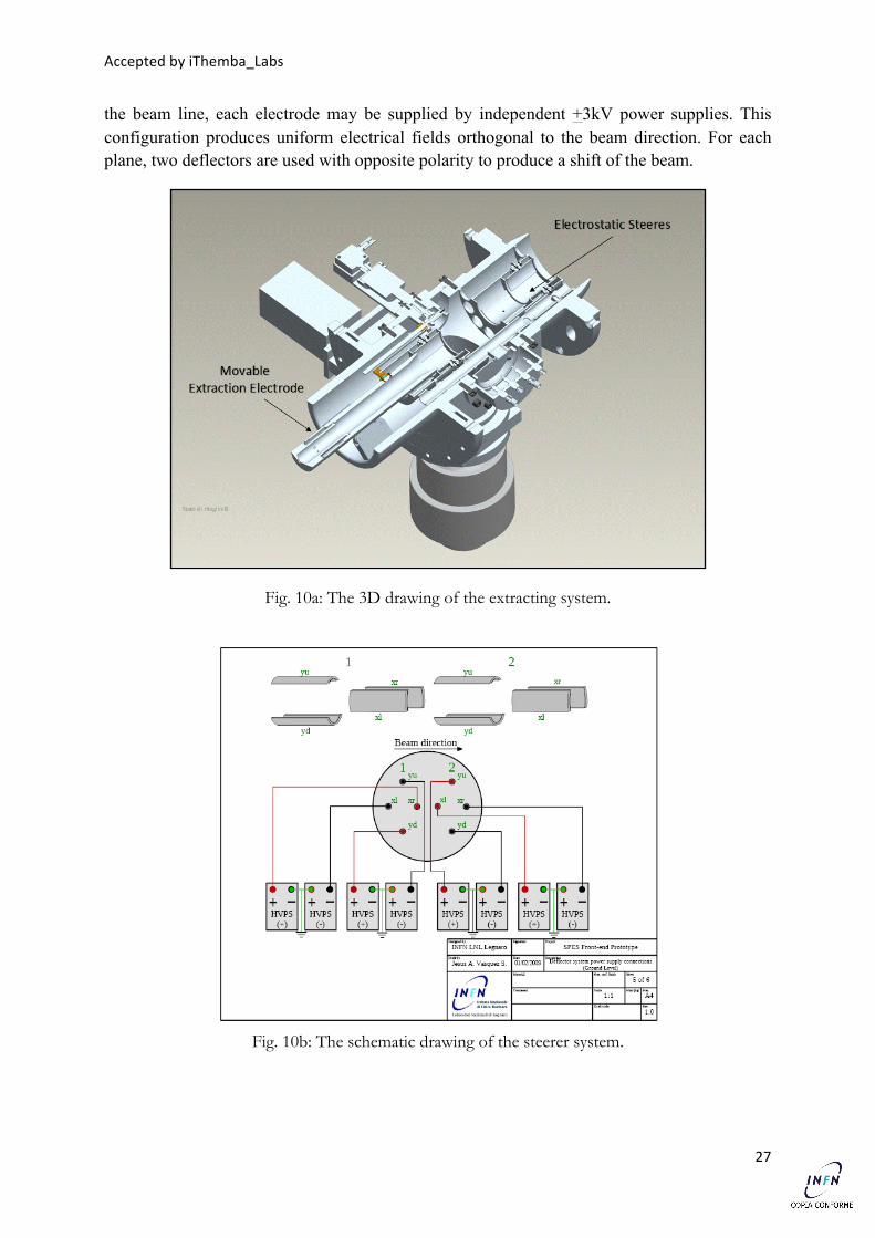
After the puller, four electrostatic steerers are installed, as reported in Figure 10a and 10b. Four couples of 60mm long cylindrical shaped plates, separated by 55mm, are mounted along
Accepted by iThemba_Labs
27
the beam line, each electrode may be supplied by independent +3kV power supplies. This configuration produces uniform electrical fields orthogonal to the beam direction. For each plane, two deflectors are used with opposite polarity to produce a shift of the beam.
Fig. 10a: The 3D drawing of the extracting system.
Fig. 10b: The schematic drawing of the steerer system.
Accepted by iThemba_Labs
28
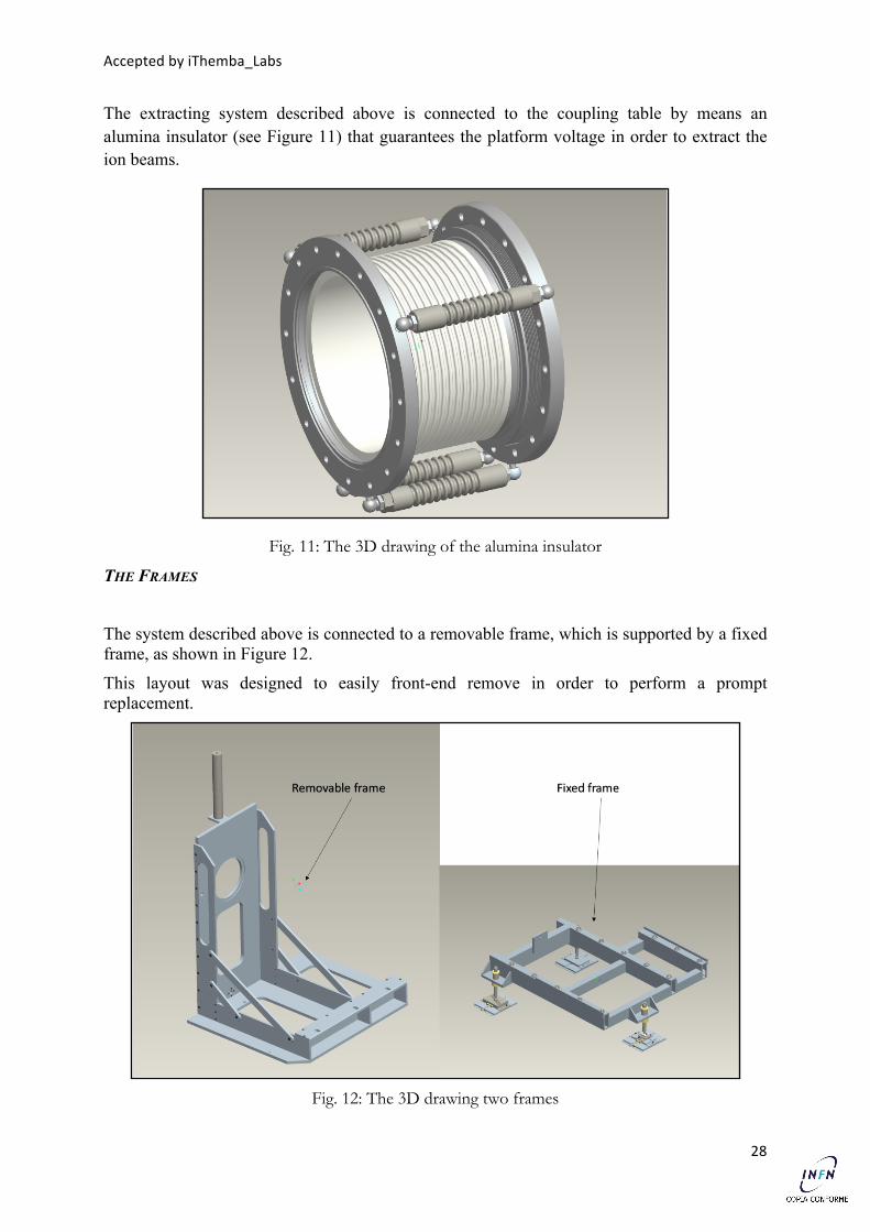
The extracting system described above is connected to the coupling table by means an alumina insulator (see Figure 11) that guarantees the platform voltage in order to extract the ion beams.
Fig. 11: The 3D drawing of the alumina insulator
THE FRAMES
The system described above is connected to a removable frame, which is supported by a fixed frame, as shown in Figure 12.
This layout was designed to easily front-end remove in order to perform a prompt replacement.
Fig. 12: The 3D drawing two frames
Accepted by iThemba_Labs
29
BUDGET AND PLANNING
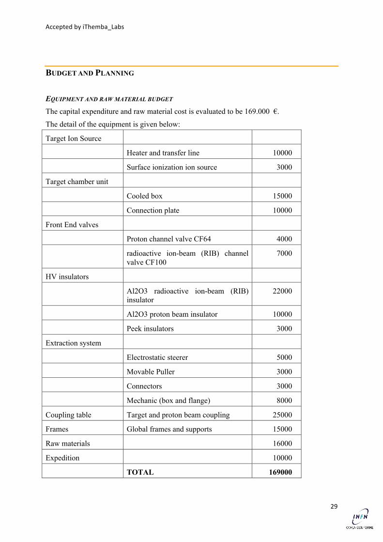
EQUIPMENT AND RAW MATERIAL BUDGET The capital expenditure and raw material cost is evaluated to be 169.000 €.
The detail of the equipment is given below:
Target Ion Source
Heater and transfer line 10000
Surface ionization ion source 3000
Target chamber unit
Cooled box 15000
Connection plate 10000
Front End valves
Proton channel valve CF64 4000
radioactive ion-beam (RIB) channel valve CF100
7000
HV insulators
Al2O3 radioactive ion-beam (RIB) insulator
22000
Al2O3 proton beam insulator 10000
Peek insulators 3000
Extraction system
Electrostatic steerer 5000
Movable Puller 3000
Connectors 3000
Mechanic (box and flange) 8000
Coupling table Target and proton beam coupling 25000
Frames Global frames and supports 15000
Raw materials 16000
Expedition 10000
TOTAL 169000
Accepted by iThemba_Labs
30
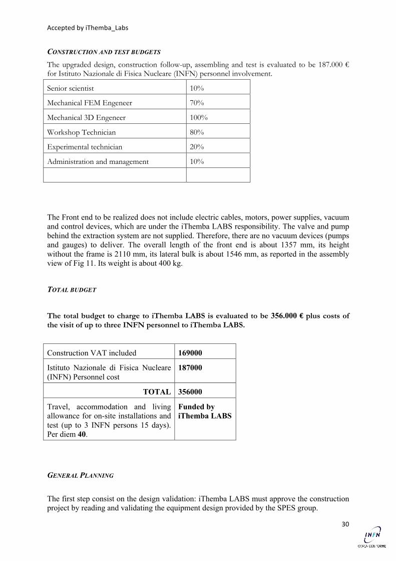
CONSTRUCTION AND TEST BUDGETS The upgraded design, construction follow-up, assembling and test is evaluated to be 187.000 € for Istituto Nazionale di Fisica Nucleare (INFN) personnel involvement.
Senior scientist 10% 10000
Mechanical FEM Engeneer 70% 50000
Mechanical 3D Engeneer 100% 60000
Workshop Technician 80% 50000
Experimental technician 20% 12000
Administration and management 10% 5000
TOTAL 187000
The Front end to be realized does not include electric cables, motors, power supplies, vacuum and control devices, which are under the iThemba LABS responsibility. The valve and pump behind the extraction system are not supplied. Therefore, there are no vacuum devices (pumps and gauges) to deliver. The overall length of the front end is about 1357 mm, its height without the frame is 2110 mm, its lateral bulk is about 1546 mm, as reported in the assembly view of Fig 11. Its weight is about 400 kg.
TOTAL BUDGET
The total budget to charge to iThemba LABS is evaluated to be 356.000 € plus costs of the visit of up to three INFN personnel to iThemba LABS.
Construction VAT included 169000
Istituto Nazionale di Fisica Nucleare (INFN) Personnel cost
187000
TOTAL 356000
Travel, accommodation and living allowance for on-site installations and test (up to 3 INFN persons 15 days). Per diem 40.
Funded by iThemba LABS
GENERAL PLANNING The first step consist on the design validation: iThemba LABS must approve the construction project by reading and validating the equipment design provided by the SPES group.
Accepted by iThemba_Labs
31
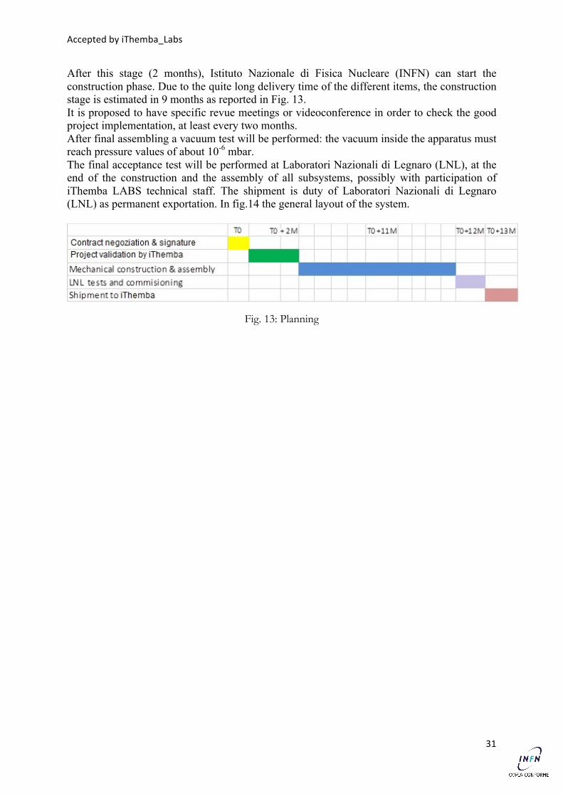
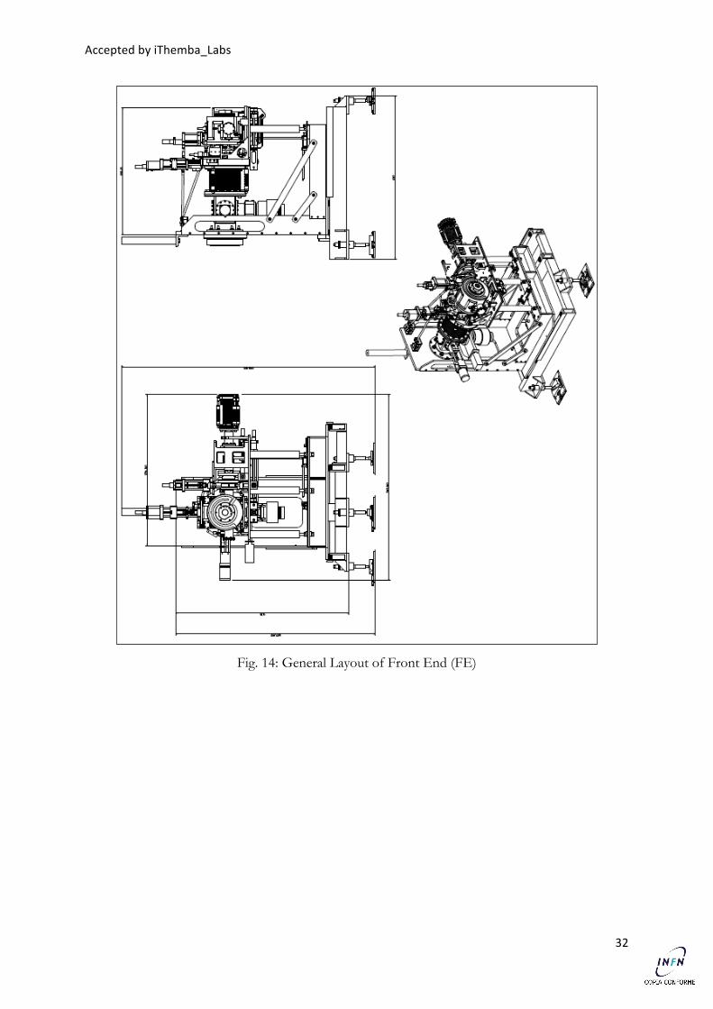
After this stage (2 months), Istituto Nazionale di Fisica Nucleare (INFN) can start the construction phase. Due to the quite long delivery time of the different items, the construction stage is estimated in 9 months as reported in Fig. 13. It is proposed to have specific revue meetings or videoconference in order to check the good project implementation, at least every two months. After final assembling a vacuum test will be performed: the vacuum inside the apparatus must reach pressure values of about 10-6 mbar. The final acceptance test will be performed at Laboratori Nazionali di Legnaro (LNL), at the end of the construction and the assembly of all subsystems, possibly with participation of iThemba LABS technical staff. The shipment is duty of Laboratori Nazionali di Legnaro (LNL) as permanent exportation. In fig.14 the general layout of the system.
Fig. 13: Planning
Accepted by iThemba_Labs
32
Fig. 14: General Layout of Front End (FE)
Accepted by iThemba_Labs
33
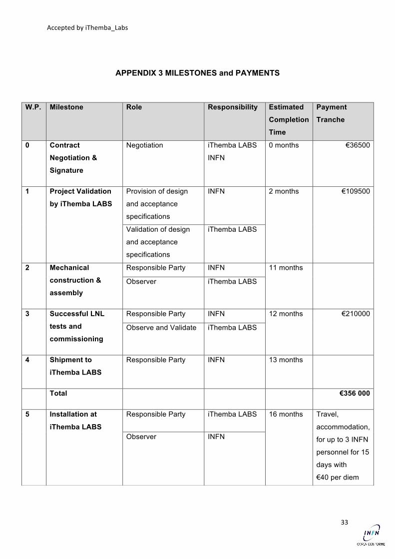
APPENDIX 3 MILESTONES and PAYMENTS
W.P. Milestone Role Responsibility Estimated
Completion
Time
Payment
Tranche
0 Contract
Negotiation &
Signature
Negotiation iThemba LABS
INFN
0 months €36500
1 Project Validation
by iThemba LABS
Provision of design
and acceptance
specifications
INFN 2 months €109500
Validation of design
and acceptance
specifications
iThemba LABS
2 Mechanical
construction &
assembly
Responsible Party INFN 11 months
Observer iThemba LABS
3 Successful LNL
tests and
commissioning
Responsible Party INFN 12 months €210000
Observe and Validate iThemba LABS
4 Shipment to
iThemba LABS
Responsible Party INFN 13 months
Total €356 000
5 Installation at
iThemba LABS
Responsible Party iThemba LABS 16 months Travel,
accommodation,
for up to 3 INFN
personnel for 15
days with
€40 per diem
Observer INFN
Accepted by iThemba_Labs
34
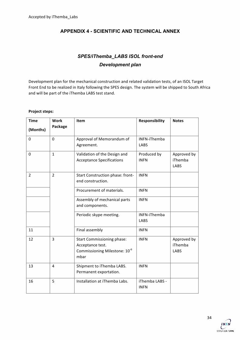
APPENDIX 4 - SCIENTIFIC AND TECHNICAL ANNEX
SPES/iThemba_LABS ISOL front-end Development plan
Development plan for the mechanical construction and related validation tests, of an ISOL Target Front End to be realized in Italy following the SPES design. The system will be shipped to South Africa and will be part of the iThemba LABS test stand.
Project steps:
Time
(Months)
Work Package
Item Responsibility Notes
0 0 Approval of Memorandum of Agreement.
INFN-‐iThemba LABS
0 1 Validation of the Design and Acceptance Specifications
Produced by INFN
Approved by iThemba LABS
2 2 Start Construction phase: front-‐end construction.
13 4 Shipment to iThemba LABS. Permanent exportation.
INFN
16 5 Installation at iThemba Labs. iThemba LABS -‐ INFN
Accepted by iThemba_Labs
35
Description
The Development plan consists on several steps:
-‐ The first step consists on the design validation. The iThemba LABS must approve the construction project by reading and validating the equipment design provided by the SPES group. The acceptance tests will be agreed upon.
-‐ After this stage (2 months), INFN can start the construction phase. Due to the quite long delivery time of the different items, the construction stage is estimated as 9 months.
It is proposed to have specific revue meetings or videoconference in order to check the good project implementation, at least every two months.
-‐ The front end tests and commissioning will be performed at Legnaro. After the final assembly of all mechanical parts and components in the LNL mechanical workshop, a mechanical, electrical and vacuum commissioning will be performed. The vacuum test of whole system is expected to reach the pressure values of about 10-‐6 mbar.
This final acceptance test will be performed, possibly, with the participation of iThemba LABS technical staff.
-‐ The shipment is duty of LNL as permanent exportation.
-‐ Finally, the technicians of iThemba LABS will perform the installation at the iThemba LABS ISOL test stand. A possible visit of INFN personnel is desirable (but not required), in order to verify the proper FE operational system behavior after transporting, reaching the vacuum values obtained in the commissioning acceptance test performed at LNL.
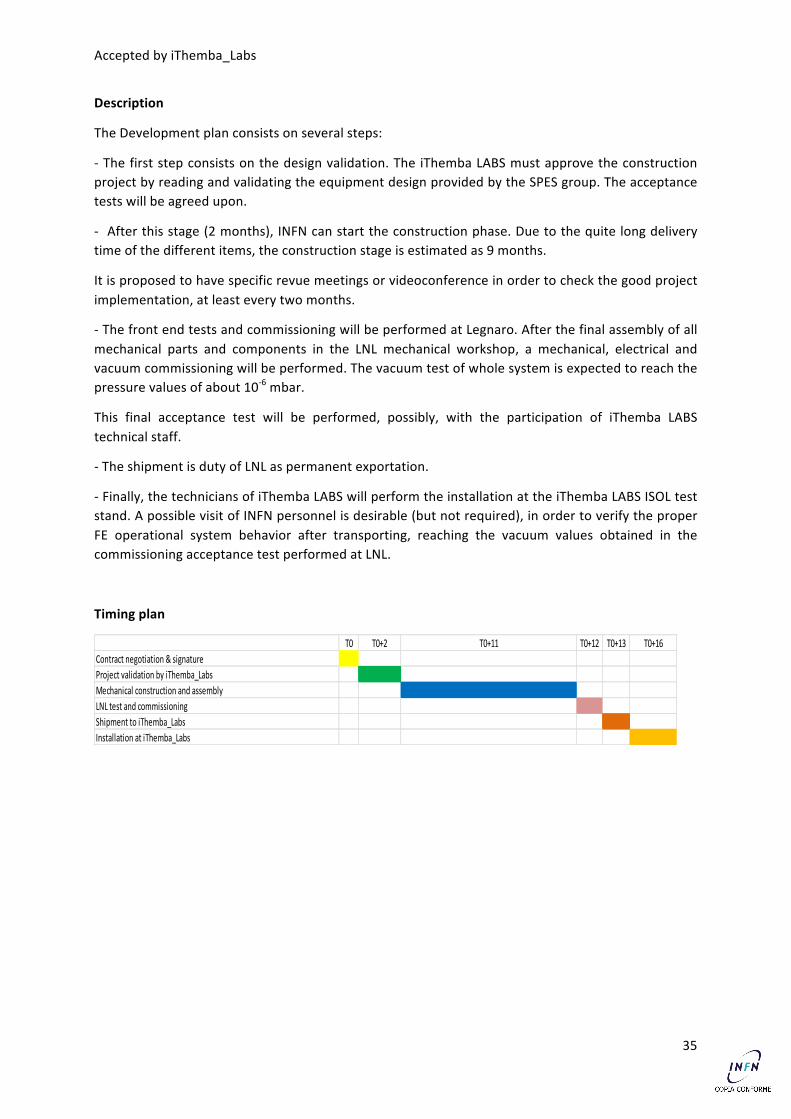
Timing plan
T0 T0+2 T0+11 T0+12 T0+13 T0+16Contract negotiation & signatureProject validation by iThemba_LabsMechanical construction and assemblyLNL test and commissioningShipment to iThemba_LabsInstallation at iThemba_Labs