GHIM Hydraulics Srl Pag.1 of 12 GHIM Hydraulics Srl – Via dell’Industria 40 – 25030 ERBUSCO (BS) – Tel. 030.7704623 – Fax. 030.7705140 – Web: www.ghim.it La GHIM si riserva il diritto di apportare senza alcun preavviso qualsiasi modifica alle caratteristiche tecniche indicate in questo documento. I dati ivi riportati non sono vincolanti. HAND PUMPS "GH" SERIES POMPE A MANO SERIE “GH” Edition 04.2006 - VCT_AEP-7X_AE_GB.doc ª Copyright – Riproduzione anche parziale vietata. Questo documento è disponibile al sito Internet: www.ghim.it TECHNICAL MANUAL “AEP-GH” CONTENTS GENERAL INFORMATION ..................................................................................................................................................................2 CAST IRON “GH” HAND PUMP RANGE ....................................................................................................................................................2 APPLICATIONS ........................................................................................................................................................................................3 RELIABILITY ............................................................................................................................................................................................3 INSTALLATION AND SERVICE .........................................................................................................................................................3 PUMP INSTALLATION...............................................................................................................................................................................4 SERVICE .................................................................................................................................................................................................4 LEVER OPERATION .................................................................................................................................................................................5 HAND PUMP “GH-HPR” WITH VALVE SPECIFICATIONS..........................................................................................................7 HAND PUMP “GH-HPI” WITH VALVE SPECIFICATIONS............................................................................................................8 HAND PUMP “GH-HPB” WITH NON RETURN VALVE ................................................................................................................9 SIMPLE ACTING “GH-HPE” HAND PUMP................................................................................................................................... 10 “GH-HPM” HAND PUMP .................................................................................................................................................................. 11 ACCESSORIES ................................................................................................................................................................................... 12 WARNING ........................................................................................................................................................................................ 12
Transcript
GHIM Hydraulics Srl Pag.1 of 12
GHIM Hydraulics Srl – Via dell’Industria 40 – 25030 ERBUSCO (BS) – Tel. 030.7704623 – Fax. 030.7705140 – Web: www.ghim.itLa GHIM si riserva il diritto di apportare senza alcun preavviso qualsiasi modifica alle caratteristiche tecniche indicate in questo documento. I dati ivi riportati non sono vincolanti.
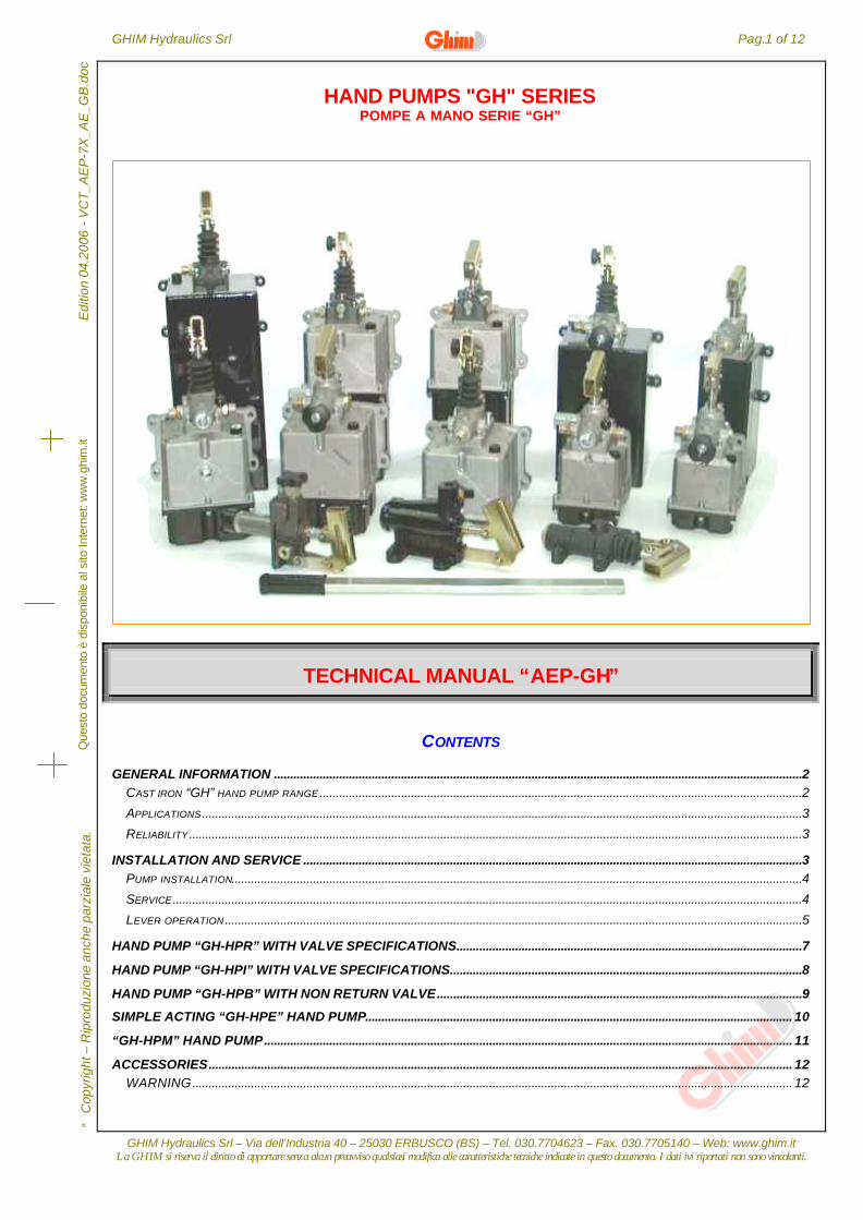
HAND PUMPS "GH" SERIESPOMPE A MANO SERIE “GH”
Edi
tion
04.2
006
- V
CT
_AE
P-7
X_A
E_G
B.d
oc
Cop
yrig
ht –
Rip
rodu
zion
e an
che
parz
iale
vie
tata
.Q
uest
o do
cum
ento
è d
ispo
nibi
le a
l sito
Inte
rnet
: ww
w.g
him
.it
TECHNICAL MANUAL “AEP-GH”
CONTENTS
GENERAL INFORMATION ..................................................................................................................................................................2CAST IRON “GH” HAND PUMP RANGE ....................................................................................................................................................2
INSTALLATION AND SERVICE .........................................................................................................................................................3PUMP INSTALLATION...............................................................................................................................................................................4
SERVICE .................................................................................................................................................................................................4
LEVER OPERATION .................................................................................................................................................................................5
HAND PUMP “GH-HPR” WITH VALVE SPECIFICATIONS..........................................................................................................7
HAND PUMP “GH-HPI” WITH VALVE SPECIFICATIONS............................................................................................................8
HAND PUMP “GH-HPB” WITH NON RETURN VALVE................................................................................................................9
SIMPLE ACTING “GH-HPE” HAND PUMP................................................................................................................................... 10
“GH-HPM” HAND PUMP.................................................................................................................................................................. 11
GHIM Hydraulics Srl – Via dell’Industria 40 – 25030 ERBUSCO (BS) – Tel. 030.7704623 – Fax. 030.7705140 – Web: www.ghim.itLa GHIM si riserva il diritto di apportare senza alcun preavviso qualsiasi modifica alle caratteristiche tecniche indicate in questo documento. I dati ivi riportati non sono vincolanti.
Edi
tion
04.2
006
- V
CT
_AE
P-7
X_A
E_G
B.d
oc
Cop
yrig
ht –
Rip
rodu
zion
e an
che
parz
iale
vie
tata
.
GENERAL INFORMATION
Thanks to GHIM HYDRAULICS’ long lasting experience in this branch, a brand new family of hand pumps with iron casthousing has added to its range of products in order to fulfill the most demanding requirements of the market
CAST IRON “GH” HAND PUMP RANGE
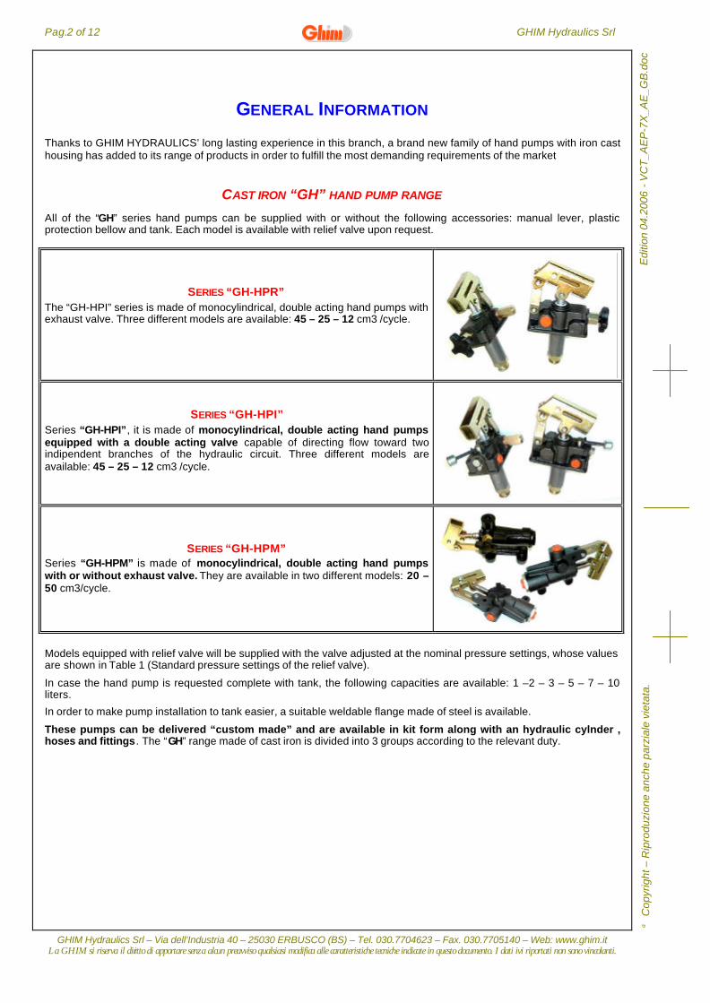
All of the “GH” series hand pumps can be supplied with or without the following accessories: manual lever, plasticprotection bellow and tank. Each model is available with relief valve upon request.
SERIES “GH-HPR”The “GH-HPI” series is made of monocylindrical, double acting hand pumps withexhaust valve. Three different models are available: 45 – 25 – 12 cm3 /cycle.
SERIES “GH-HPI”Series “GH-HPI”, it is made of monocylindrical, double acting hand pumpsequipped with a double acting valve capable of directing flow toward twoindipendent branches of the hydraulic circuit. Three different models areavailable: 45 – 25 – 12 cm3 /cycle.
SERIES “GH-HPM”Series “GH-HPM” is made of monocylindrical, double acting hand pumpswith or without exhaust valve. They are available in two different models: 20 –50 cm3/cycle.
Models equipped with relief valve will be supplied with the valve adjusted at the nominal pressure settings, whose valuesare shown in Table 1 (Standard pressure settings of the relief valve).
In case the hand pump is requested complete with tank, the following capacities are available: 1 –2 – 3 – 5 – 7 – 10liters.
In order to make pump installation to tank easier, a suitable weldable flange made of steel is available.
These pumps can be delivered “custom made” and are available in kit form along with an hydraulic cylnder ,hoses and fittings. The “GH” range made of cast iron is divided into 3 groups according to the relevant duty.
GHIM Hydraulics Srl Pag.3 of 12
GHIM Hydraulics Srl – Via dell’Industria 40 – 25030 ERBUSCO (BS) – Tel. 030.7704623 – Fax. 030.7705140 – Web: www.ghim.itLa GHIM si riserva il diritto di apportare senza alcun preavviso qualsiasi modifica alle caratteristiche tecniche indicate in questo documento. I dati ivi riportati non sono vincolanti.
C
opyr
ight
– R
ipro
duzi
one
anch
e pa
rzia
le v
ieta
ta.
Edi
tion
04.2
006
- V
CT
_AE
P-7
X_A
E_G
B.d
oc
APPLICATIONS
The hand pumps in object can be used for several applications, such as INDUSTRY, AGRICOLTURE,TRANSPORTATIONS, MILITARY and NAVAL.
RELIABILITY
The accurate design followed by severe testing procedures applied on the homologation benches and labs allowed us toachieve a very high degree of reliability and lifetime of our products. The body of pump is normally supply with surfacephosphate treatment. Under request the body of pump is available painted or zinc plated.
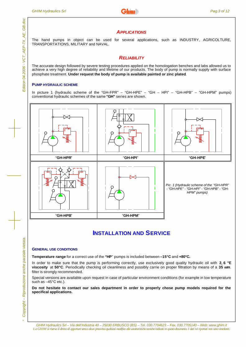
PUMP HYDRAULIC SCHEME
In picture 1 (hydraulic scheme of the “GH-FPR” – “GH-HPE” – “GH – HPI” – “GH-HPB” – “GH-HPM” pumps)conventional hydraulic schemes of the same “GH” series are shown.
“GH-HPR” “GH-HPI” “GH-HPE”
“GH-HPB” “GH-HPM”
Pic. 1 (Hydraulic scheme of the “GH-HPR”- “GH-HPE” - “GH-HPI” - “GH-HPB” - “GH-
HPM” pumps)
INSTALLATION AND SERVICE
GENERAL USE CONDITIONS
Temperature range for a correct use of the “HP” pumps is included between –15°C and +80°C.
In order to make sure that the pump is performing correctly, use exclusively good quality hydraulic oil with 2÷6 °Eviscosity at 50°C. Periodically checking oil cleanliness and possibly carrie on proper filtration by means of a 35 µm.filter is strongly recommended.
Special versions are available upon request in case of particular environment conditions (for example in low temperaturesuch as –45°C etc.).
Do not hesitate to contact our sales department in order to properly chose pump models required for thespecifical applications.
Pag.4 of 12 GHIM Hydraulics Srl
GHIM Hydraulics Srl – Via dell’Industria 40 – 25030 ERBUSCO (BS) – Tel. 030.7704623 – Fax. 030.7705140 – Web: www.ghim.itLa GHIM si riserva il diritto di apportare senza alcun preavviso qualsiasi modifica alle caratteristiche tecniche indicate in questo documento. I dati ivi riportati non sono vincolanti.
Edi
tion
04.2
006
- V
CT
_AE
P-7
X_A
E_G
B.d
oc
Cop
yrig
ht –
Rip
rodu
zion
e an
che
parz
iale
vie
tata
.
PUMP INSTALLATION
“HP” PUMP FITTING POSITIONS
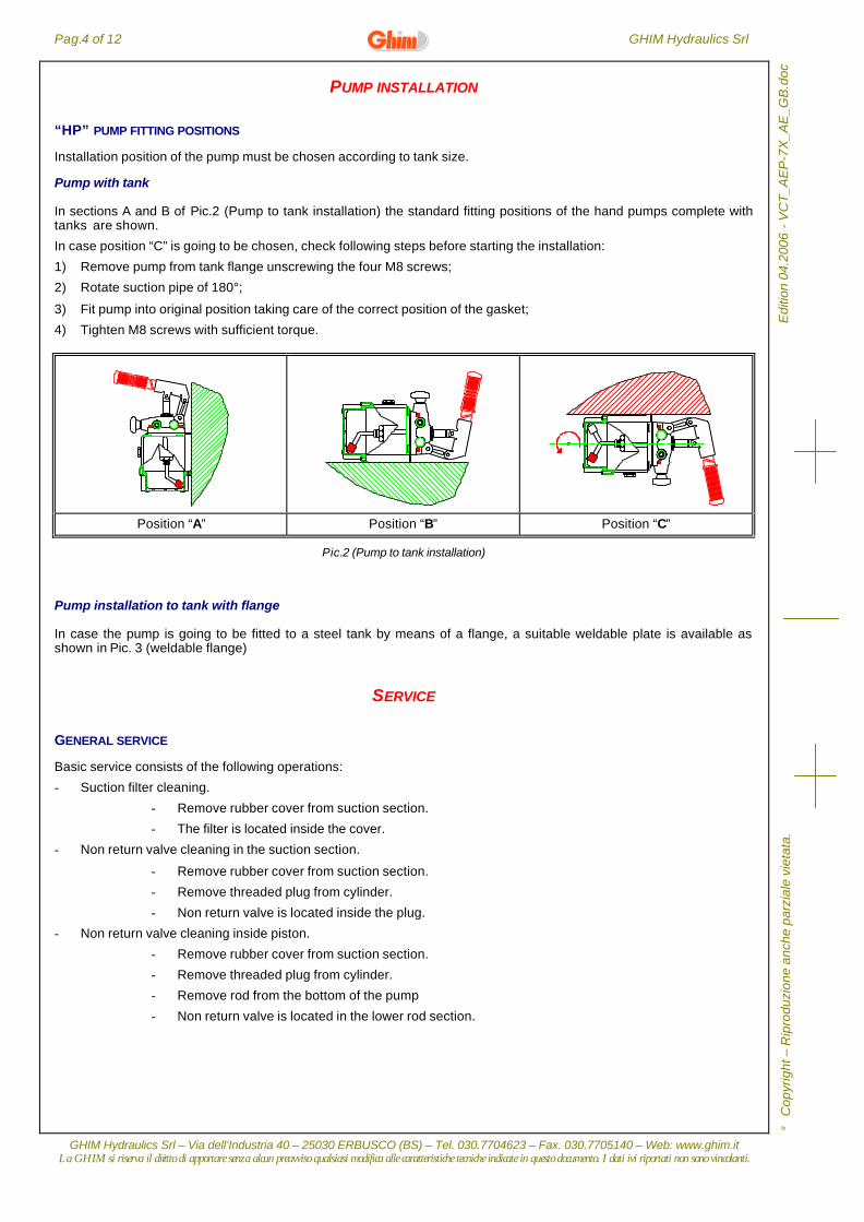
Installation position of the pump must be chosen according to tank size.
Pump with tank
In sections A and B of Pic.2 (Pump to tank installation) the standard fitting positions of the hand pumps complete withtanks are shown.
In case position “C” is going to be chosen, check following steps before starting the installation:
1) Remove pump from tank flange unscrewing the four M8 screws;
2) Rotate suction pipe of 180°;
3) Fit pump into original position taking care of the correct position of the gasket;
4) Tighten M8 screws with sufficient torque.
Position “A” Position “B” Position “C”
Pic.2 (Pump to tank installation)
Pump installation to tank with flange
In case the pump is going to be fitted to a steel tank by means of a flange, a suitable weldable plate is available asshown in Pic. 3 (weldable flange)
SERVICE
GENERAL SERVICE
Basic service consists of the following operations:
- Suction filter cleaning.
- Remove rubber cover from suction section.
- The filter is located inside the cover.
- Non return valve cleaning in the suction section.
- Remove rubber cover from suction section.
- Remove threaded plug from cylinder.
- Non return valve is located inside the plug.
- Non return valve cleaning inside piston.
- Remove rubber cover from suction section.
- Remove threaded plug from cylinder.
- Remove rod from the bottom of the pump
- Non return valve is located in the lower rod section.
GHIM Hydraulics Srl Pag.5 of 12
GHIM Hydraulics Srl – Via dell’Industria 40 – 25030 ERBUSCO (BS) – Tel. 030.7704623 – Fax. 030.7705140 – Web: www.ghim.itLa GHIM si riserva il diritto di apportare senza alcun preavviso qualsiasi modifica alle caratteristiche tecniche indicate in questo documento. I dati ivi riportati non sono vincolanti.
C
opyr
ight
– R
ipro
duzi
one
anch
e pa
rzia
le v
ieta
ta.
Edi
tion
04.2
006
- V
CT
_AE
P-7
X_A
E_G
B.d
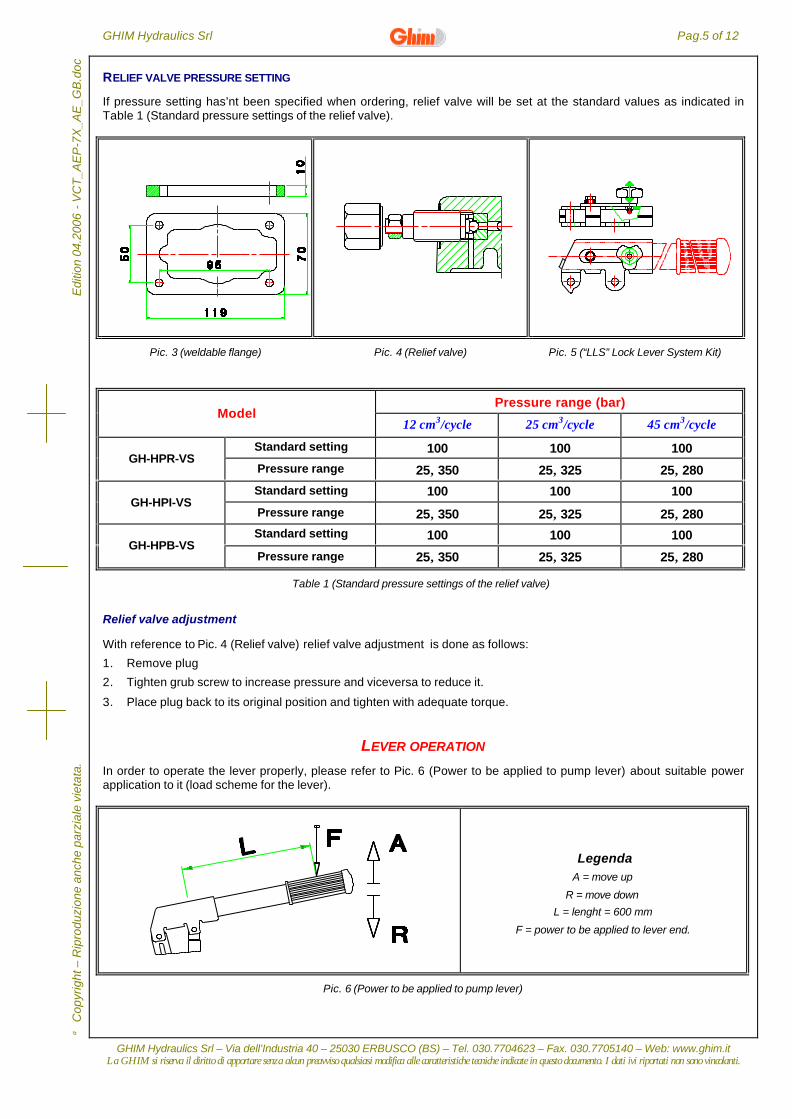
ocRELIEF VALVE PRESSURE SETTING
If pressure setting has’nt been specified when ordering, relief valve will be set at the standard values as indicated inTable 1 (Standard pressure settings of the relief valve).
Pic. 3 (weldable flange) Pic. 4 (Relief valve) Pic. 5 (“LLS” Lock Lever System Kit)
Pressure range (bar)Model
12 cm3/cycle 25 cm3/cycle 45 cm3/cycle
Standard setting 100 100 100GH-HPR-VS
Pressure range 25÷350 25÷325 25÷280
Standard setting 100 100 100GH-HPI-VS
Pressure range 25÷350 25÷325 25÷280Standard setting 100 100 100
GH-HPB-VSPressure range 25÷350 25÷325 25÷280
Table 1 (Standard pressure settings of the relief valve)
Relief valve adjustment
With reference to Pic. 4 (Relief valve) relief valve adjustment is done as follows:
1. Remove plug
2. Tighten grub screw to increase pressure and viceversa to reduce it.
3. Place plug back to its original position and tighten with adequate torque.
LEVER OPERATION
In order to operate the lever properly, please refer to Pic. 6 (Power to be applied to pump lever) about suitable powerapplication to it (load scheme for the lever).
LegendaA = move up
R = move down
L = lenght = 600 mm
F = power to be applied to lever end.
Pic. 6 (Power to be applied to pump lever)
Pag.6 of 12 GHIM Hydraulics Srl
GHIM Hydraulics Srl – Via dell’Industria 40 – 25030 ERBUSCO (BS) – Tel. 030.7704623 – Fax. 030.7705140 – Web: www.ghim.itLa GHIM si riserva il diritto di apportare senza alcun preavviso qualsiasi modifica alle caratteristiche tecniche indicate in questo documento. I dati ivi riportati non sono vincolanti.
Edi
tion
04.2
006
- V
CT
_AE
P-7
X_A
E_G
B.d
oc
Cop
yrig
ht –
Rip
rodu
zion
e an
che
parz
iale
vie
tata
.
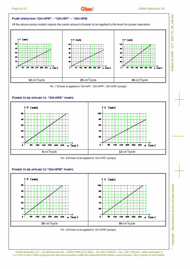
PUMP OPERATION “GH-HPR” - “GH-HPI” – “GH-HPB
All the above pump models require the same amount of power to be applied to the lever for proper operation.
12 cm3/cycle 25 cm3/cycle 45 cm3/cycle
Pic. 7 (Power to applied to “GH-HPI”, “GH-HPR”, “GH-HPB” pumps)
POWER TO BE APPLIED TO “GH-HPE” PUMPS
8 cm3/cycle 12 cm3/cycle
Pic. 8 (Power to be applied to “GH-HPE” pumps)
POWER TO BE APPLIED TO “GH-HPM” PUMPS
20 cm3/cycle 50 cm3/cycle
Pic. 9 (Power to be applied to “GH-HPM” pumps)
GHIM Hydraulics Srl Pag.7 of 12
GHIM Hydraulics Srl – Via dell’Industria 40 – 25030 ERBUSCO (BS) – Tel. 030.7704623 – Fax. 030.7705140 – Web: www.ghim.itLa GHIM si riserva il diritto di apportare senza alcun preavviso qualsiasi modifica alle caratteristiche tecniche indicate in questo documento. I dati ivi riportati non sono vincolanti.
C
opyr
ight
– R
ipro
duzi
one
anch
e pa
rzia
le v
ieta
ta.
Edi
tion
04.2
006
- V
CT
_AE
P-7
X_A
E_G
B.d
oc
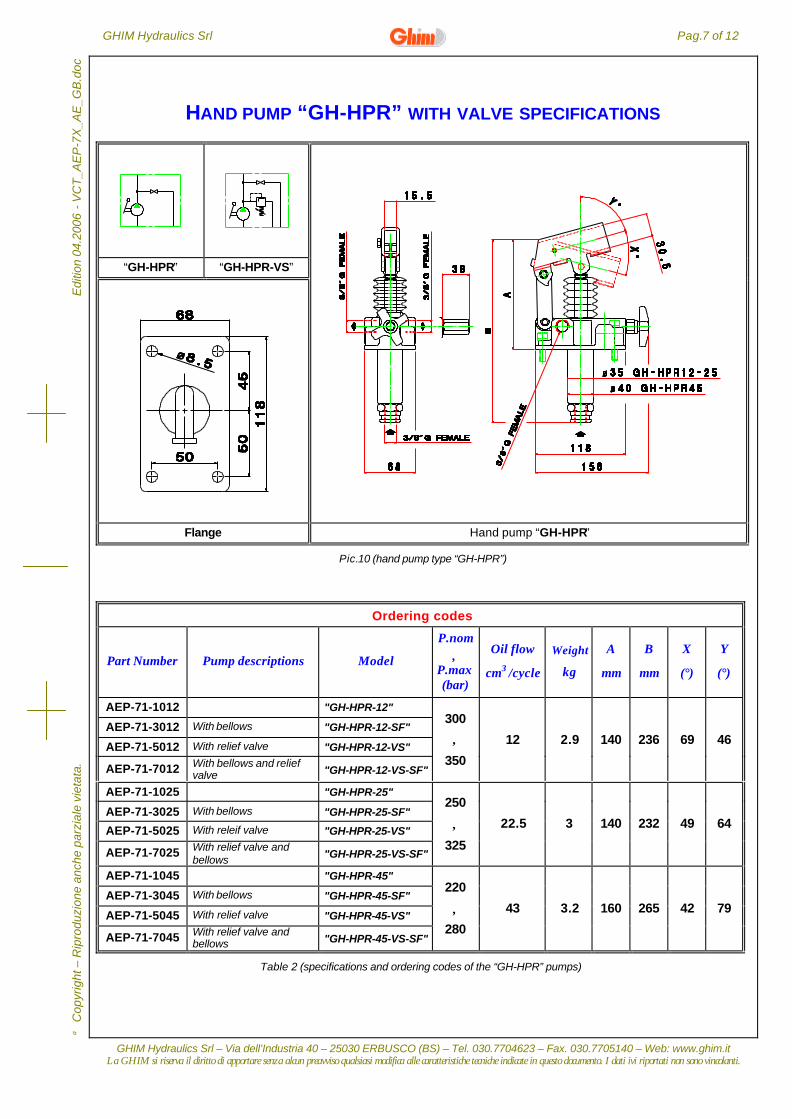
HAND PUMP “GH-HPR” WITH VALVE SPECIFICATIONS
“GH-HPR” “GH-HPR-VS”
Flange Hand pump “GH-HPR”
Pic.10 (hand pump type “GH-HPR”)
Ordering codes
Part Number Pump descriptions Model
P.nom÷
P.max(bar)
Oil flow
cm3 /cycle
Weight
kg
A
mm
B
mm
X
(°)
Y
(°)
AEP-71-1012 "GH-HPR-12"
AEP-71-3012 With bellows "GH-HPR-12-SF"
AEP-71-5012 With relief valve "GH-HPR-12-VS"
AEP-71-7012 With bellows and reliefvalve "GH-HPR-12-VS-SF"
300
÷
350
12 2.9 140 236 69 46
AEP-71-1025 "GH-HPR-25"
AEP-71-3025 With bellows "GH-HPR-25-SF"
AEP-71-5025 With releif valve "GH-HPR-25-VS"
AEP-71-7025 With relief valve andbellows "GH-HPR-25-VS-SF"
250
÷
325
22.5 3 140 232 49 64
AEP-71-1045 "GH-HPR-45"
AEP-71-3045 With bellows "GH-HPR-45-SF"
AEP-71-5045 With relief valve "GH-HPR-45-VS"
AEP-71-7045 With relief valve andbellows "GH-HPR-45-VS-SF"
220
÷
280
43 3.2 160 265 42 79
Table 2 (specifications and ordering codes of the “GH-HPR” pumps)
Pag.8 of 12 GHIM Hydraulics Srl
GHIM Hydraulics Srl – Via dell’Industria 40 – 25030 ERBUSCO (BS) – Tel. 030.7704623 – Fax. 030.7705140 – Web: www.ghim.itLa GHIM si riserva il diritto di apportare senza alcun preavviso qualsiasi modifica alle caratteristiche tecniche indicate in questo documento. I dati ivi riportati non sono vincolanti.
Edi
tion
04.2
006
- V
CT
_AE
P-7
X_A
E_G
B.d
oc
Cop
yrig
ht –
Rip
rodu
zion
e an
che
parz
iale
vie
tata
.
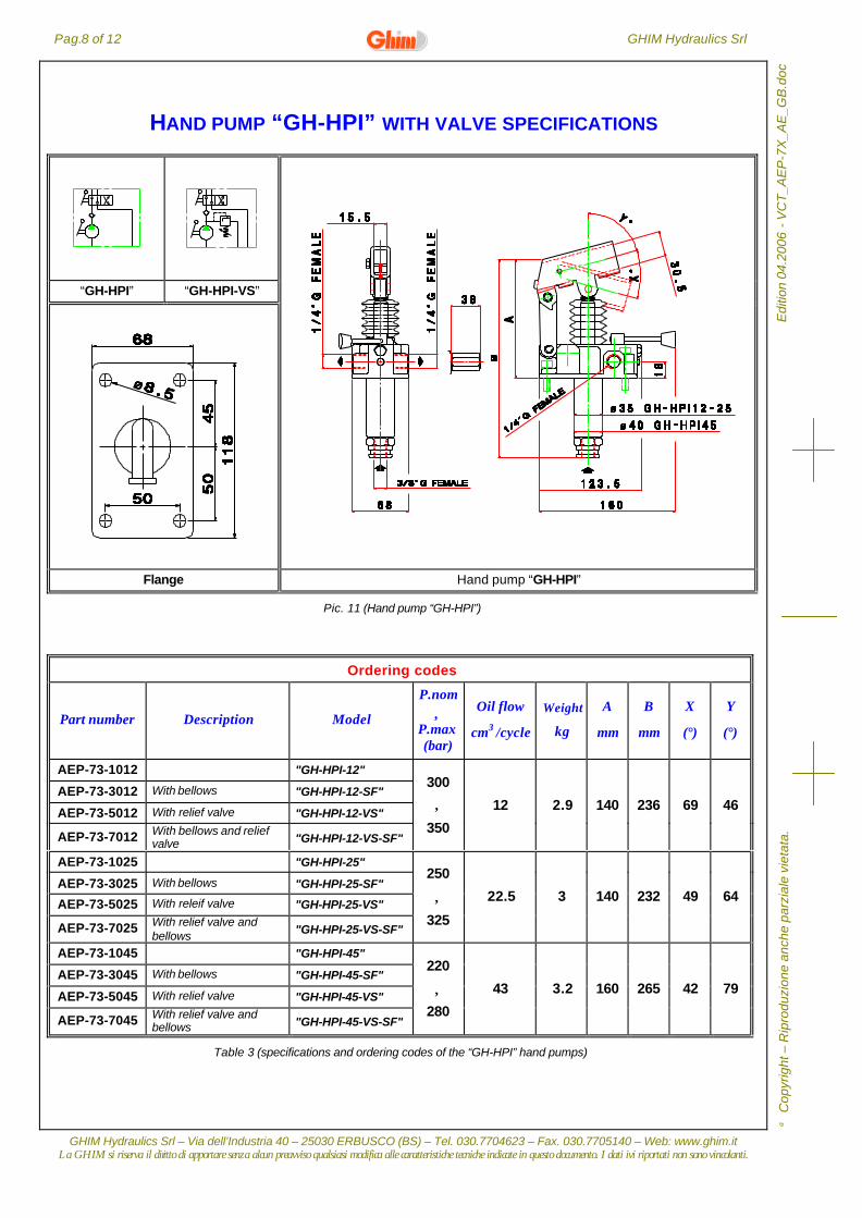
HAND PUMP “GH-HPI” WITH VALVE SPECIFICATIONS
“GH-HPI” “GH-HPI-VS”
Flange Hand pump “GH-HPI”
Pic. 11 (Hand pump “GH-HPI”)
Ordering codes
Part number Description Model
P.nom÷
P.max(bar)
Oil flow
cm3 /cycle
Weight
kg
A
mm
B
mm
X
(°)
Y
(°)
AEP-73-1012 "GH-HPI-12"
AEP-73-3012 With bellows "GH-HPI-12-SF"
AEP-73-5012 With relief valve "GH-HPI-12-VS"
AEP-73-7012 With bellows and reliefvalve "GH-HPI-12-VS-SF"
300
÷
350
12 2.9 140 236 69 46
AEP-73-1025 "GH-HPI-25"
AEP-73-3025 With bellows "GH-HPI-25-SF"
AEP-73-5025 With releif valve "GH-HPI-25-VS"
AEP-73-7025 With relief valve andbellows "GH-HPI-25-VS-SF"
250
÷
325
22.5 3 140 232 49 64
AEP-73-1045 "GH-HPI-45"
AEP-73-3045 With bellows "GH-HPI-45-SF"
AEP-73-5045 With relief valve "GH-HPI-45-VS"
AEP-73-7045 With relief valve andbellows "GH-HPI-45-VS-SF"
220
÷
280
43 3.2 160 265 42 79
Table 3 (specifications and ordering codes of the “GH-HPI” hand pumps)
GHIM Hydraulics Srl Pag.9 of 12
GHIM Hydraulics Srl – Via dell’Industria 40 – 25030 ERBUSCO (BS) – Tel. 030.7704623 – Fax. 030.7705140 – Web: www.ghim.itLa GHIM si riserva il diritto di apportare senza alcun preavviso qualsiasi modifica alle caratteristiche tecniche indicate in questo documento. I dati ivi riportati non sono vincolanti.
C
opyr
ight
– R
ipro
duzi
one
anch
e pa
rzia
le v
ieta
ta.
Edi
tion
04.2
006
- V
CT
_AE
P-7
X_A
E_G
B.d
oc
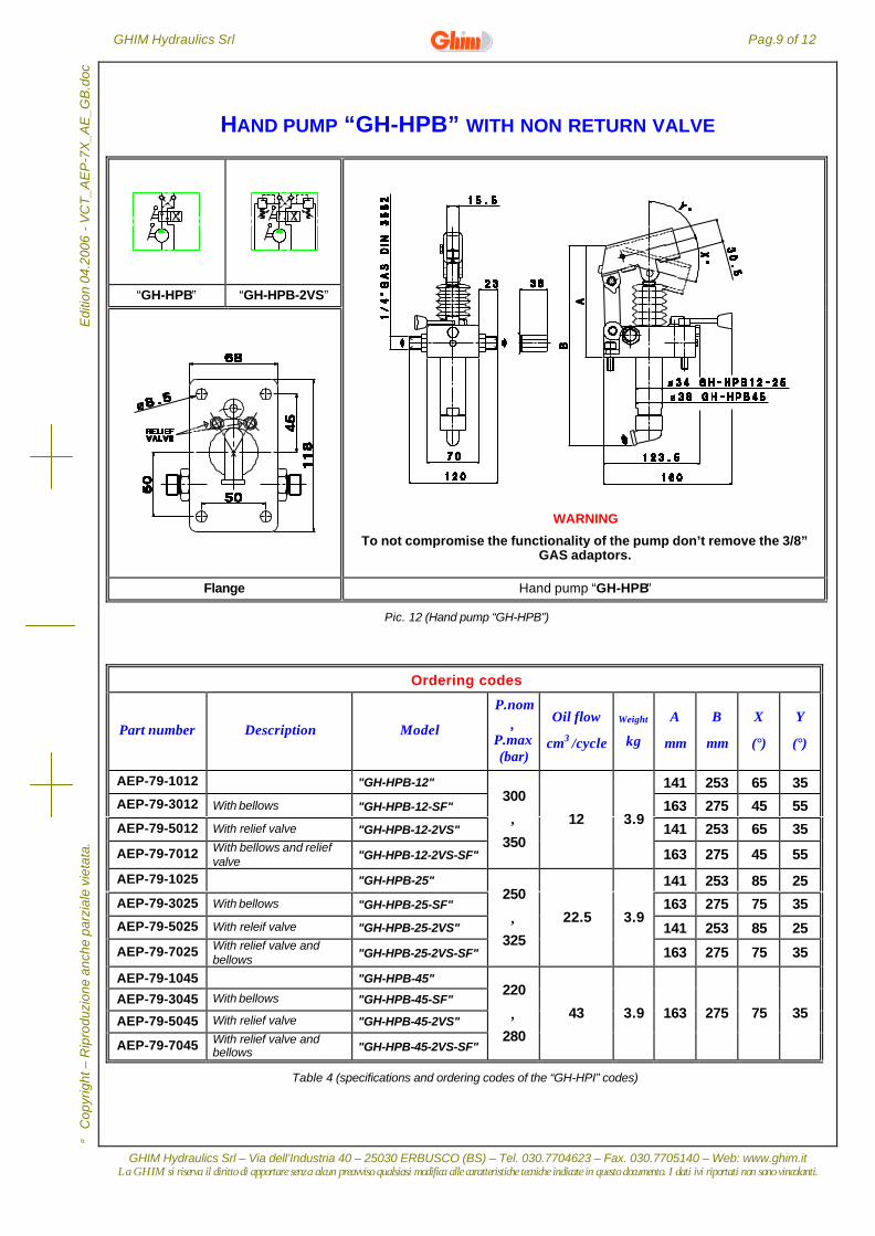
HAND PUMP “GH-HPB” WITH NON RETURN VALVE
“GH-HPB” “GH-HPB-2VS”
WARNING
To not compromise the functionality of the pump don’t remove the 3/8”GAS adaptors.
AEP-79-5012 With relief valve "GH-HPB-12-2VS" 141 253 65 35
AEP-79-7012 With bellows and reliefvalve "GH-HPB-12-2VS-SF"
300
÷
350
12 3.9
163 275 45 55
AEP-79-1025 "GH-HPB-25" 141 253 85 25
AEP-79-3025 With bellows "GH-HPB-25-SF" 163 275 75 35
AEP-79-5025 With releif valve "GH-HPB-25-2VS" 141 253 85 25
AEP-79-7025 With relief valve andbellows "GH-HPB-25-2VS-SF"
250
÷
325
22.5 3.9
163 275 75 35
AEP-79-1045 "GH-HPB-45"
AEP-79-3045 With bellows "GH-HPB-45-SF"
AEP-79-5045 With relief valve "GH-HPB-45-2VS"
AEP-79-7045 With relief valve andbellows "GH-HPB-45-2VS-SF"
220
÷
280
43 3.9 163 275 75 35
Table 4 (specifications and ordering codes of the “GH-HPI” codes)
Pag.10 of 12 GHIM Hydraulics Srl
GHIM Hydraulics Srl – Via dell’Industria 40 – 25030 ERBUSCO (BS) – Tel. 030.7704623 – Fax. 030.7705140 – Web: www.ghim.itLa GHIM si riserva il diritto di apportare senza alcun preavviso qualsiasi modifica alle caratteristiche tecniche indicate in questo documento. I dati ivi riportati non sono vincolanti.
Edi
tion
04.2
006
- V
CT
_AE
P-7
X_A
E_G
B.d
oc
Cop
yrig
ht –
Rip
rodu
zion
e an
che
parz
iale
vie
tata
.
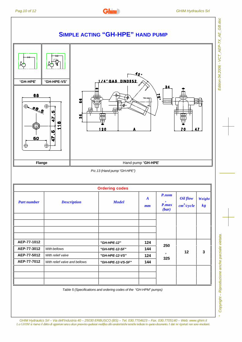
SIMPLE ACTING “GH-HPE” HAND PUMP
“GH-HPE” “GH-HPE-VS”
Flange Hand pump “GH-HPE”
Pic.13 (Hand pump “GH-HPE”)
Ordering codes
Part number Description ModelA
mm
P.nom÷
P.max(bar)
Oil flow
cm3/cycle
Weight
kg
AEP-77-1012 "GH-HPE-12" 124
AEP-77-3012 With bellows "GH-HPE-12-SF" 144
AEP-77-5012 With relief valve "GH-HPE-12-VS" 124AEP-77-7012 With relief valve and bellows "GH-HPE-12-VS-SF" 144
250
÷
325
12 3
Table 5 (Specifications and ordering codes of the “GH-HPM” pumps)
GHIM Hydraulics Srl Pag.11 of 12
GHIM Hydraulics Srl – Via dell’Industria 40 – 25030 ERBUSCO (BS) – Tel. 030.7704623 – Fax. 030.7705140 – Web: www.ghim.itLa GHIM si riserva il diritto di apportare senza alcun preavviso qualsiasi modifica alle caratteristiche tecniche indicate in questo documento. I dati ivi riportati non sono vincolanti.
C
opyr
ight
– R
ipro
duzi
one
anch
e pa
rzia
le v
ieta
ta.
Edi
tion
04.2
006
- V
CT
_AE
P-7
X_A
E_G
B.d
oc
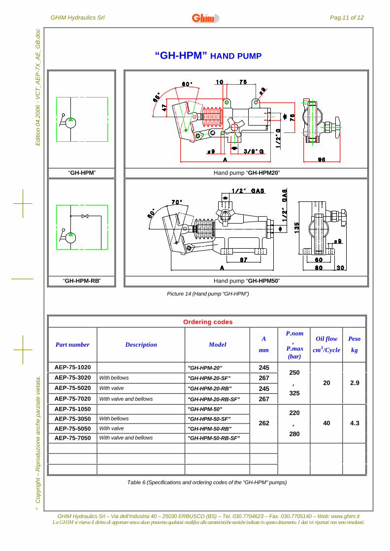
“GH-HPM” HAND PUMP
“GH-HPM” Hand pump “GH-HPM20”
“GH-HPM-RB” Hand pump “GH-HPM50”
Picture 14 (Hand pump “GH-HPM”)
Ordering codes
Part number Description ModelA
mm
P.nom÷
P.max(bar)
Oil flow
cm3/Cycle
Peso
kg
AEP-75-1020 "GH-HPM-20" 245
AEP-75-3020 With bellows "GH-HPM-20-SF" 267
AEP-75-5020 With valve "GH-HPM-20-RB" 245
AEP-75-7020 With valve and bellows "GH-HPM-20-RB-SF" 267
250
÷
325
20 2.9
AEP-75-1050 "GH-HPM-50"
AEP-75-3050 With bellows "GH-HPM-50-SF"
AEP-75-5050 With valve "GH-HPM-50-RB"
AEP-75-7050 With valve and bellows "GH-HPM-50-RB-SF"
262
220
÷
280
40 4.3
Table 6 (Specifications and ordering codes of the “GH-HPM” pumps)
Pag.12 of 12 GHIM Hydraulics Srl
GHIM Hydraulics Srl – Via dell’Industria 40 – 25030 ERBUSCO (BS) – Tel. 030.7704623 – Fax. 030.7705140 – Web: www.ghim.itLa GHIM si riserva il diritto di apportare senza alcun preavviso qualsiasi modifica alle caratteristiche tecniche indicate in questo documento. I dati ivi riportati non sono vincolanti.
Edi
tion
04.2
006
- V
CT
_AE
P-7
X_A
E_G
B.d
oc
Cop
yrig
ht –
Rip
rodu
zion
e an
che
parz
iale
vie
tata
.
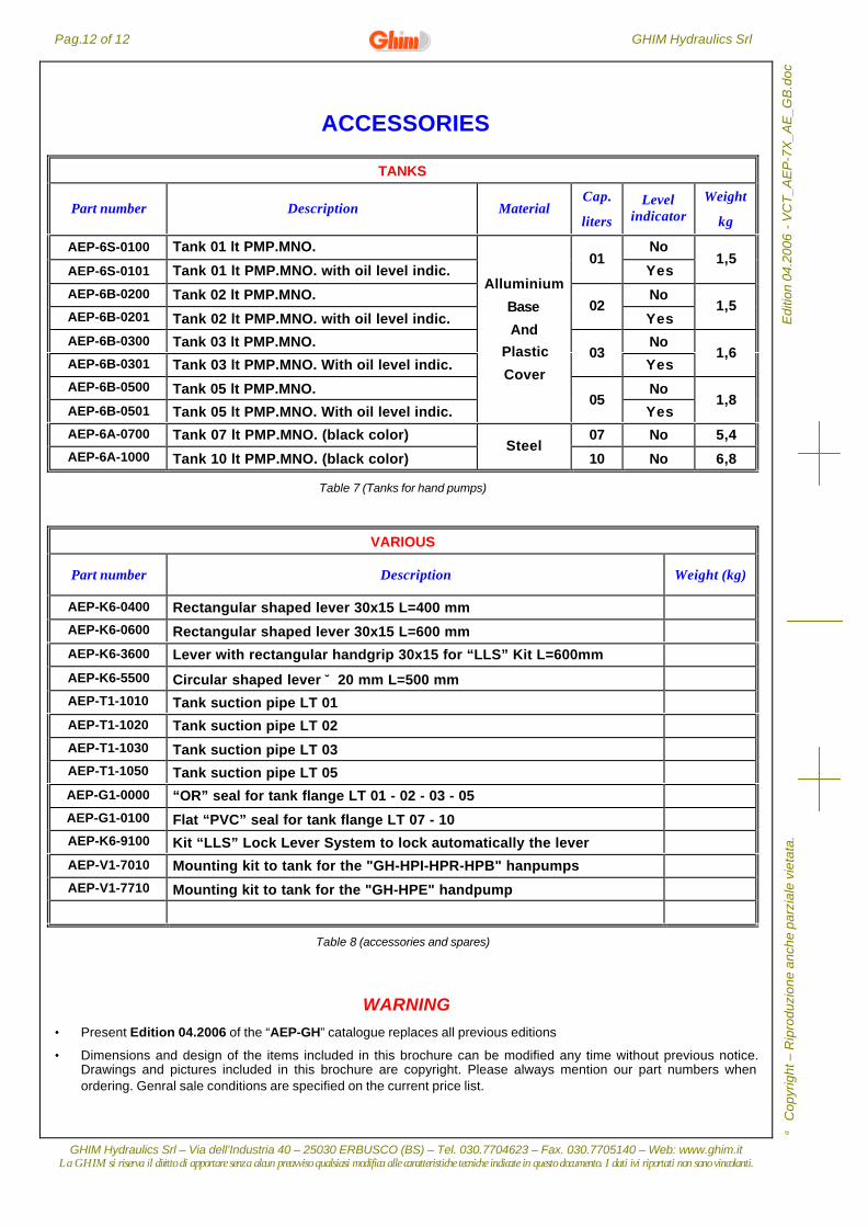
ACCESSORIES
TANKS
Part number Description MaterialCap.
liters
Levelindicator
Weight
kg
AEP-6S-0100 Tank 01 lt PMP.MNO. No
AEP-6S-0101 Tank 01 lt PMP.MNO. with oil level indic.01
Yes1,5
AEP-6B-0200 Tank 02 lt PMP.MNO. No
AEP-6B-0201 Tank 02 lt PMP.MNO. with oil level indic.02
Yes1,5
AEP-6B-0300 Tank 03 lt PMP.MNO. No
AEP-6B-0301 Tank 03 lt PMP.MNO. With oil level indic.03
Yes1,6
AEP-6B-0500 Tank 05 lt PMP.MNO. No
AEP-6B-0501 Tank 05 lt PMP.MNO. With oil level indic.
Alluminium
Base
And
Plastic
Cover
05Yes
1,8
AEP-6A-0700 Tank 07 lt PMP.MNO. (black color) 07 No 5,4
AEP-6A-1000 Tank 10 lt PMP.MNO. (black color)Steel
10 No 6,8
Table 7 (Tanks for hand pumps)
VARIOUS
Part number Description Weight (kg)
AEP-K6-0400 Rectangular shaped lever 30x15 L=400 mm
AEP-K6-0600 Rectangular shaped lever 30x15 L=600 mm
AEP-K6-3600 Lever with rectangular handgrip 30x15 for “LLS” Kit L=600mm
AEP-K6-5500 Circular shaped lever ∅20 mm L=500 mmAEP-T1-1010 Tank suction pipe LT 01
AEP-T1-1020 Tank suction pipe LT 02
AEP-T1-1030 Tank suction pipe LT 03AEP-T1-1050 Tank suction pipe LT 05
AEP-G1-0000 “OR” seal for tank flange LT 01 - 02 - 03 - 05
AEP-G1-0100 Flat “PVC” seal for tank flange LT 07 - 10AEP-K6-9100 Kit “LLS” Lock Lever System to lock automatically the lever
AEP-V1-7010 Mounting kit to tank for the "GH-HPI-HPR-HPB" hanpumps
AEP-V1-7710 Mounting kit to tank for the "GH-HPE" handpump
Table 8 (accessories and spares)
WARNING• Present Edition 04.2006 of the “AEP-GH” catalogue replaces all previous editions
• Dimensions and design of the items included in this brochure can be modified any time without previous notice.Drawings and pictures included in this brochure are copyright. Please always mention our part numbers whenordering. Genral sale conditions are specified on the current price list.